
Related Manuals for Agilent Technologies E5072A


Summary of Contents for Agilent Technologies E5072A
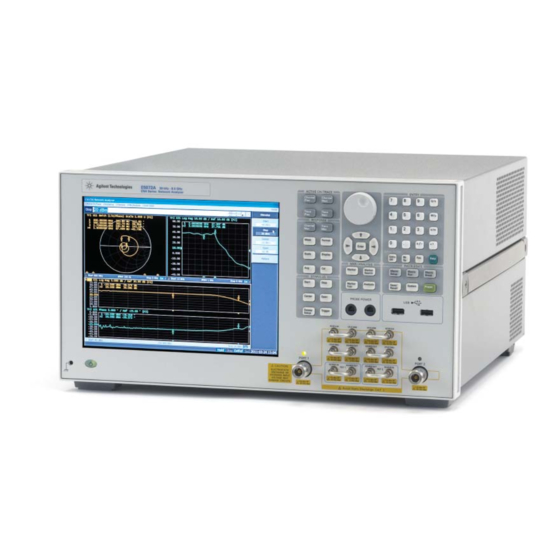
- Page 1 Agilent E5072A ENA Series Network Analyzer 30 kHz to 4.5 /8.5 GHz Configuration Guide...
-
Page 2: Ordering Guide
Ordering Guide The following steps will guide you through configuring your E5072A. 1-year return to Agilent service warranty is included as standard Standard furnished item Description Additional information Installation guide Contains the information necessary to start up with the E5072A. - Page 3 Step 5. Choose accessory option (Optional. If not required, go to step 6) Option no Description E5072A-1CM Rack mount kit E5072A-1CN Front handle kit E5072A-1CP Rack mount and Front handle kit E5072A-810 Add keyboard E5072A-820 Add mouse Step 6. Choose calibration option (Optional. If not required, go to step 7)
-
Page 4: Calibration Kits
Test Accessories and Calibration Kits Test accessories and calibration kits that can be used with the E5072A are listed in this section. A complete line of test accessories and calibration kits can be found at the Agilent RF and Microwave Test Accessories Web site: www.agilent.com/find/accessories... - Page 5 USB power sensor, 10 MHz to 18 GHz, Type-N (m) U2001A/B/H USB power sensor, 10 MHz to 6 GHz, Type-N (m) U2004A USB power sensor, 9 kHz to 6 GHz, Type-N (m) 1. Order the 82357B USB/GPIB interface to control a power meter by the E5072A...
-
Page 6: Calibration Kit
Calibration kit Model No Description Mechanical calibration kits 85032F 50 Ω standard calibration kit, DC to 9 GHz. Includes; ● Type-N (m) fi xed load ● Type-N (f) fi xed load ● Type-N (m) Open ● Type-N (f) Open ● Type-N (m) Short ●... - Page 7 Port 2 REF 2 REF 1 Figure1. Simplifi ed test set block diagram E5072A Network Analyzer Upgrades The following upgrade kits are available for adding the options of the E5072A Option no Description E5072AU-008 Add frequency offset mode (Customer installable)
-
Page 8: Web Resources
Literature Resource You can find detail information about the key features, application examples, and technical specification of the E5072A in the following document. Literature number Description 5990-8001EN E5072A Network Analyzer Confi guration Guide 5990-8002EN E5072A Network Analyzer Data Sheet 5990-8003EN... - Page 9 0200-88 22 55 United Kingdom 44 (0) 118 9276201 For other unlisted Countries: www.agilent.com/find/contactus Revised: October 14, 2010 Product specifications and descriptions in this document subject to change without notice. © Agilent Technologies, Inc. 2011 Printed in USA, May 30, 2011 5990-8001EN...