Page 1
Right choice for ultimate yield LSIS strives to maximize customers' profit in gratitude of choosing us for your partner. Programmable Logic Controller 
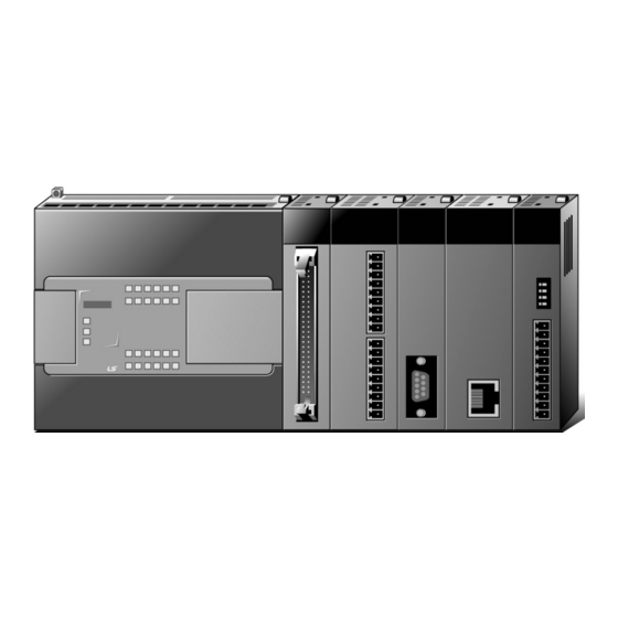
XGB Ethernet/IP IF Module XGT Series User’s Manual XBL-EIPT Read this manual carefully before installing, wiring, operating, servicing or inspecting this equipment.
Page 2
Safety Instruction Before using the product … For your safety and effective operation, please read the safety instructions thoroughly before using the product. ► Safety Instructions should always be observed in order to prevent accident or risk with the safe and proper use the product.
Page 3
Safety Instruction Safety Instructions for design process Warning Please install a protection circuit on the exterior of PLC so that the whole system may operate safely regardless of failures from external power or PLC. Any abnormal output or operation from PLC may cause serious problems to safety in whole system. Install protection units on the exterior of PLC like an interlock circuit that deals with opposite operations such as emergency stop, protection circuit, and forward/reverse rotation or install an interlock circuit that deals with high/low limit under its position controls.
Page 4
Safety Instruction Safety Instructions for design process Caution I/O signal or communication line shall be wired at least 100mm away from a high-voltage cable or power line. Fail to follow this Safety Instructions on installation process Caution Use PLC only in the environment specified in PLC manual or general standard of data sheet.
Page 5
Safety Instruction Safety Instructions for wiring process Warning Prior to wiring works, make sure that every power is turned off. If not, electric shock or damage on the product may be caused. After wiring process is done, make sure that terminal covers are installed properly before ...
Page 6
Safety Instruction Safety Instructions for test-operation and maintenance Warning Don’t touch the terminal when powered. Electric shock or abnormal operation may occur. Prior to cleaning or tightening the terminal screws, let all the external power off including PLC power. If not, electric shock or abnormal operation may occur. ...
Page 7
Safety Instruction Safety Instructions for waste disposal Caution Product or battery waste shall be processed as industrial waste. The waste may discharge toxic materials or explode itself.
Page 8
V 1.0 ’10.11 First edition V 2.0 ’17. 4 Add service setting by tag XG5000 V4.0 UI updated Entire ※ The number of User’s manual is indicated right part of the back cover. ⓒ 2010 LSIS Co., Ltd All Rights Reserved.
Page 9
User’s Manual. The User’s Manual describes the product. If necessary, you may refer to the following description and order accordingly. In addition, you may connect our website (http://www.lsis.com/) and download the information as a PDF file.
Page 10
About User’s Manual Current XBL-EIPT manual is written based on the following version. Related OS version list Product name OS version XGB-XBCH V2.80 XGB-XBCS V1.90 XGB-XBCU V1.70 XGB-XBMH V1.10 XGB-XBMS V3.80 XGB-XECH V2.20 XGB-XECS V1.80 XGB-XECU V1.70 XG5000 V4.21...
3.3 The Order for Setting up Products till Running -------------------------------------------------------------------------------------------- 3-3 3.4 Available device area ----------------------------------------------------------------------------------------------------------------------------- 3-4 3.5 Installation of Products -------------------------------------------------------------------------------------------------------------------------- 3-6 3.5.1 Installation of XBL-EIPT -------------------------------------------------------------------------------------------------------------- 3-6 3.6 Trial- Run ------------------------------------------------------------------------------------------------------------------------------------------- 3-8 3.6.1 Directions when Configuring Systems -------------------------------------------------------------------------------------------- 3-8 Chapter 4 System Configuration 4.1 Configuration of a Usable System ----------------------------------------------------------------------------------------------------------- 4-1...
Page 12
Contents 5.1.3 Confirmation on the Installation of USB Device Driver ------------------------------------------------------------------------ 5-7 5.2 How to Register Communication Modules ----------------------------------------------------------------------------------------------- 5-15 5.2.1 In case of Offline ----------------------------------------------------------------------------------------------------------------------- 5-15 5.2.2 In case of Online ---------------------------------------------------------------------------------------------------------------------- 5-17 5.2.3 In case of Reading Parameter stored in PLC ---------------------------------------------------------------------------------- 5-19 5.2.4 How to Set-up Modules ------------------------------------------------------------------------------------------------------------- 5-20 5.2.5 Menu bar and shortcut of XG5000 ------------------------------------------------------------------------------------------------- 5-21 Chapter 6 EIP Service...
PLC and EtherNet/IP I/F IO module. To use the communication service by Tag, the following version is necessary. 1) XBL-EIPT: V2.0 or above 2) XBC Series: SU(V1.90 or above), H(V2.80 or above), U(V1.70 or above) 3) XEC Series: SU(V1.80 or above), H(V2.20 or above), U(V1.70 or above) 4) XBM Series: S(V3.80 or above), H(V1.10 or above)
Chapter 1 Overview 1.2 Features XGB EtherNet/IP I/F Module have the following features. (1) Communication Methods: Extensive Client Messaging Support ▶ Encapsulated Messages, UCMM Explicit Messaging ▶ Class 3 Connected Explicit Messaging(Server Only) ▶ Class 1 Connected Implicit(IO) Messaging(Cyclic I/O Service Only) (2) Compatibility: XGT EtherNet/IP I/F meet EtherNet/IP Conformance Test Suite Version 2.10 (3) 100BASE-TX media is provided and 100Mbps/ (Full Duplex) are supported.
Chapter 1 Overview 1.3 Product Components 1.3.1 Indication of Type Names Components of XGB EtherNet/IP I/F module product are described. Type Name Components Remarks XBL-EIPT Electric 2 –port EtherNet/IP Module More than category 5...
1) To use the above program, download from the current website you are visiting. In case you can not use the internet, visit near agencies and ask for CD-ROM for installation. Internet Web - address: http://www.lsis.com 2) To program XG5000, use RS-232C port and USB of CPU module. For cable, refer to the XGB catalogue.
Chapter 1 Overview 1.4.3 Confirmation of Versions Check out the version of the module before using XGB EtherNet/IP I/F. Confirmation through XG5000 To read the information of a communication module, access to the communication module. If interface is normally maintained with CPU, the information like the following illustration can be got. (1) Execute XG5000 (2) Connect with CPU via access through [Online]-[Connect] on menu.
XGB EtherNet/IP I/F module changed from OS V2.0 to Tag communication. To use the communication service by Tag, refer to the following description. 1.5.1 Version information available with communication service by Tag XBL-EIPT: V2.0, EDS: Ver2.10 XG5000: V4.21 XG5000 Software: V4.21 or above XBC Series: SU(V1.90 or above), H(V2.80 or above), U(V1.70 or above) XEC Series: SU(V1.80 or above), H(V2.20 or above), U(V1.70 or above)
• Peak acceleration: 147 m/s (15G) Shock • Duration: 11ms IEC61131-2 resistance • Half-sine, 3 times each direction per each axis AC: ±1,500 V Square wave LSIS standard DC: ±900 V Impulse noise IEC61131-2 Electrostatic discharge 4kV (Contact discharge) IEC61000-1-2 Noise resistance IEC61131-2,...
Chapter 2 Specification 2.2 Performance Specification The following table describes the specification of system configuration in accordance with EtherNet/IP I/F module’s media. When you configure systems, refer to the below table. Item Standard Transmission Speed 100Mbps Transmission Method Base Band Maximum Extension Distance 100m Transmission...
Chapter 2 Specification 2.3 Name of Each Part The name in each module is as follows. LED Display IP Set-up Switch Connector 1 LOG Switch Connector 2 [Figure 2.3.1] The Front View for Module PLC ▶ LED Names and Contents Silk Mark LED State Contents...
Page 22
Chapter 2 Specification ▶ Log Switch In case of reading Log in communication module and needing to store the Log, if you push it for more than 1 second, it is stored into Flash area from Memory area. The Log in the memory area is the one erased when power is supplied again and the Log in Flash area is the one which is maintained when power is supplied again.
Chapter 2 Specification 2.4 Cable Standards 2.4.1 UTP Cable UTP cable is classified into the 3 types according to the following standards. ▶ With or without Shield: 3 Types (UTP, FTP, STP) ▶ Used - frequency Band: 7 Categories (Category 1 ~ Category 7) ▶...
Page 24
Chapter 2 Specification Classification by Frequencies used Transmission Classification Frequency used (MHz) Uses Speed(Mbps) Category 1 Voice Frequency Telephone Network (2 Pair) Category 2 Multi- Pair Communication Cable Telephone Network + Computation Category 3 Network 1) Computation Network – Transmission Category 4 Speed Up 2)Low-loss Communication Cable...
Page 25
Chapter 2 Specification An Example (CTP-LAN5) of Category - 5 Twisted Pair Cable(UTP) Items Units Values Conductor Resistance Ω/km 93.5 (Maximum) Insulation Resistance MΩ/km 2500 (Minimum) Anti- voltage V/minute AC 500 Characteristic Ω(1~100MHz) 100 ± 15 Impedance 10MHz Attenuation Less than dB/100m 16MHz 20MHz 10MHz...
Chapter 3 Installation and Trial-Run Chapter 3 Installation and Trial- Run 3.1 Installation Environment This product is very reliable regardless of installation environments, but to guaranty the reliability and stability of the system, pay attention to the following items. Environment Conditions (1) Install in the control board where waterproof and dustproof are possible.
Chapter 3 Installation and Trial-Run 3.2 Cautions when Handling Observe the following directions when you configure the system using EtherNet/IP I/F module. 1) Do not drop or impose strong impact. 2) Do not separate PCB from the case. It may cause malfunctions. 3) Make sure foreign objects are not put into the upper area of the module while you do wiring jobs.
Chapter 3 Installation and Trial-Run 3.3 The Order for Setting up Products till Running The following describes the order of installing or setting up products. Install the system and setting up the parameter so that they can operate in order. Start ●...
Chapter 3 Installation and Trial-Run 3.4 Available device area Available device areas for each basic unit are as follows Size CPU type Area Range Reference (word) P0~P127 Read/Write/Monitor available, XBMS P0~P1023 1024 Read/Write/Monitor available, XBCH, XBCS, XBMH P0~P2047 2048 Read/Write/Monitor available, XBCU M0~M255 Read/Write/Monitor available, XBMS M0~M1023...
Page 30
1) F Device: Writeable address is F220 or later. 2) In case of XBL-EIPT V2.0 or later: XEC type can only use I, Q, M, R, and W devices as EIP variable in global variable. 3) T / C is a timer / counter device. Bit designation means contact value and Word designation means current value.
Chapter 3 Installation and Trial-Run 3.5 Installation of Products 3.5.1 Installation of XBL-EIPT Twist Pair Cable 8 Pin - RJ45 Plug [Figure 3.6.1] How to Install 100BASE-TX The maximum segment distance of 100BASE-TX reaches 100m. (The distance between modules) Straight cables and cross cables are used.
Page 32
Chapter 3 Installation and Trial-Run How to Install (1) For reliable transmission of 100Mbps signal using UTP cables, Patch Cord, Line Cord, Patch Panel, DVO(Data Voice Outlet), etc must meet 5 spec (Category 5 Spec.- EIA/TIA-568A). (2) Make sure the length of patch code will be over 7m in cross-connect, If the length exceeds 7m, the length corresponding to 90m, as much as the allowable value in Horizontal Distribution System, must be deducted.
Chapter 3 Installation and Trial-Run 3.6 Trial- Run 3.6.1 Directions when Configuring Systems To use P2P service including this module, make sure IP Addresses of all stations are different from IP addresses of all other stations. To use communication cables, select the ones in designated sizes. Using cables that have not been designated may cause serious communication obstacles.
Chapter 4 System Configuration Chapter 4 System Configuration XGB EtherNet/IP I/F modules can be installed on the XBC CPU modules. The number of maximum installments reaches 2 . It is possible for the communication system using this module to be applied to a variety of configurations. This chapter describes the examples of the cases when system configuration is available and unavailable by applications.
2 communication ports. 4.2.2 Configuration of a Ring System (Configuration of a XBL-EIPT Ring) EtherNet/IP I/F does not support a ring system. When you configure a ring form, it is necessary to set up the IP address switch of the module –...
5.1 Installation and Execution of Software To use software XG5000, it is necessary to install XG5000. Then, XBL-EIPT V1.x should use XG5000 V3.1 or later, XBL- EIPT V2.0 or later should use XG5000 V4.21 or later. The requirements for system needed to execute are as follows.
Page 37
Chapter 5 Installation of Software and communication Parameters Click [Next] button. Insert a company’s name and press [Next] button. Designate the folder that XG5000 will be installed. If you want to change the folder, click [Browse] and enter or select new folder. As XG5000 needs installation space of 500MByte, select the disk with enough room. If the installation room is not enough, warning message is on and thus, it is impossible to proceed to next step.
Page 38
Chapter 5 Installation of Software and communication Parameters Check out the installation path and press [Next] button. Install as follows. XG5000 USB device drive install screen appears while installing, and soon, installation is completed as follows.
Chapter 5 Installation of Software and communication Parameters 5.1.2 Installation of USB Device Drive When you install XG5000 into Window XP for the first time, install USB Device Drive additionally. Even if USB is not connected, install USB device drive as follows. However, in Window 2000, USB device drive is automatically installed when XG5000 is installed, and in Window XP, install it additionally.
Page 40
Chapter 5 Installation of Software and communication Parameters 5) Select [Search for the best driver in these locations] of drive search options and check out [Include this location in the search] 6) Press [Browse] button Select Drivers Folder where XG5000 has been installed in “Browse for Folder”...
Page 41
Chapter 5 Installation of Software and communication Parameters Press [Ok] button. The computer searches for the folder you selected. 8) If the computer selects the most suitable device drive, it will ask to install the device driver selected. As USB device driver stably operates in Window operating system, press the button [Continue].
Chapter 5 Installation of Software and communication Parameters 5.1.3 Confirmation on the Installation of USB Device Driver If USB is not connected, confirm the installation of device driver as follows. (1) Click the right button in [My Computer] on the desktop and select menu [Manage]. The computer management dialogue box appears like this.
Page 43
Chapter 5 Installation of Software and communication Parameters (1) In case of normal state If the list [LSIS XGSeries] located in the lower of [Universal Serial Bus controllers] appears, the device driver has been normally installed. (2) In case of abnormal state The following illustration appears, it is the case the device drive has not normally been installed.
Page 44
Chapter 5 Installation of Software and communication Parameters (5) Hardware Update Wizard Dialogue Box appears. Select Option [Install from a list or specific location (Advanced)] List and press next button. The following procedures are manual and are the same to the installation of the device driver.
Page 45
Chapter 5 Installation of Software and communication Parameters If not installed, reinstall according to the following order. (1) In case a device driver has been wrongly installed or is problematic, execute Hardware Update Wizard Start. (2) Select Option [Installation from a List or a specific location (Advanced)] List and press next button. (3) On search and installation options, select [Don’t Search.
Page 46
Chapter 5 Installation of Software and communication Parameters (4) Click [Have Disk…] on the Dialog Box below. (5) If Installation Dialogue Box appears from the disc appears, press button [Browse.] 5-11...
Page 47
Chapter 5 Installation of Software and communication Parameters (6) Move to the folder File XG5000 has been installed from File Search Dialogue Box. If drivers fold selected, GmUSBD.inf file appears. Select this file and press button [Open.]. (7)The directory with device driver files appears on the location of the manufacture’s file. Press button [Ok.]. 5-12...
Page 48
Chapter 5 Installation of Software and communication Parameters (8) On the compatible H/W display list of the device driver Select Dialog Box, select “LSIS XGSeries” driver and then click [Next] button. (9)The Dialogue Box for Hardware Installation appears. Press button [Continue] and proceed with installation.
Page 49
Chapter 5 Installation of Software and communication Parameters (10)Dialogue Box for Hardware Update Wizard Completed appears. Press button [Finish] and complete the installation of device drive. 5-14...
Chapter 5 Installation of Software and communication Parameters 5.2 How to Register Communication Modules To use Ethernet/IP I/F module, communication parameter must be made up in XG5000 and to set up the system on Ethernet/IP I/F module, the module must be registered to XG5000. How to register Ethernet/IP I/F module located at discretion is as follows in accordance with the state of on/off line.
Page 51
Chapter 5 Installation of Software and communication Parameters [Fig 5.2.5] Add module c) [Communication module settings] -> select module type, base, slot [Fig. 5.2.6] Communication module setting Ethernet/IP module is registered on Slot 1 of Base 0 is as shown below; [Fig.
Chapter 5 Installation of Software and communication Parameters 5.2.2 In case of Online To register the communication module in online state, using XG5000, the methods in NO. 1 and NO. 2 are the same as the one in registering modules of EtherNet/IP in offline state. The execution order afterwards is as follows. If not connected, check out the state of connection with PLC or select [Online ]->...
Page 53
Chapter 5 Installation of Software and communication Parameters 5-18...
Chapter 5 Installation of Software and communication Parameters 5.2.3 In case of Reading Parameter stored in PLC The method for reading the basic set-up values for the communication module stored in PLC and for reading P2P set- up values are in the below order. 1) Select [Project.] ...
Chapter 5 Installation of Software and communication Parameters 5.2.4 How to Set-up Modules To operate EtherNet/IP I/F modules, set up in the following order. Execution Order (1) Enter in the Project Window Please refer to 5.2.1 In case of Offline. (2) I/O Information –...
Chapter 5 Installation of Software and communication Parameters 5.2.5 Menu bar and shortcut of XG5000 The following is menu bar and short cut of XG5000. (For other menus, refer to XG5000 User’s Manual) Menu bar Menu Icon Contents New Project Creates a new project.
Page 57
Chapter 5 Installation of Software and communication Parameters Menu bar Menu Icon Contents Connect/Disconnect Connects or disconnects with PLC. Connect Settings Specifies the connection method. Change Mode Changes PLC mode. Reads parameter/program/comment from Read PLC. Write Writes parameter/program/comment on PLC. Online Compares the project to the project saved in Compare with PLC...
Chapter 6 EIP Service Chapter 6 EIP Service 6.1 EtherNet/IP Communication Method The communicant methods of EtherNet/IP are divided into Implicit Communication Method and Explicit Communication Method and each method is again divided into client and server function. In XGB EtherNet/IP IF module, Implicit communication method is provided by periodic client /periodic server and explicit communication method is provided by aperiodic client/aperiodic server.
Chapter 6 EIP Service 6.1.3 Periodic Communication (Implicit) System Implicit Message provided in periodic communication in XGB EtherNet/IP I/F module means a suggestive and implied message. As this message contains header information to the minimum except for the data in frame, it also refers to the message which is impossible to see what data means.
Page 60
Chapter 6 EIP Service Operating procedure of periodic communication is as follows. Client Server Destination port : 44818 ① Receiving port: 44818 Connection request (SYN) Connection ② Connection request response (SYN ACK) Connection ③ Connection confirm response Session register (ACK) request ④...
Chapter 6 EIP Service 6.1.4 Aperiodic Communication (Explicit) System Explicit Message provided in aperiodic communication from XGB EtherNet/IP I/F module means clear and explicit message. This message also means that all information which is possible to translate data to date frame. Thus, even though it takes some time to translate frame, if the message we want is sent without the process of setting parameter, frame is translated from server and the response is made.
Page 62
2) Tag setting / Local tag: When XBL-EIPT V2.0 or later is used, tag name can be up to 38 characters for XBC/XBM and up to 46 characters for XEC. This is the maximum number of variable names including the members of the structure.
Page 63
Chapter 6 EIP Service Operating procedure of aperiodic communication is as follows. Client Server Destination port : 44818 ① Receiving port: 44818 Connection request (SYN) Connection ② Connection request response (SYN ACK) Connection ③ Connection confirm response Session register (ACK) request ④...
6.2 EIP Service EtherNet/IP is divided into a periodic message service (Implicit Service), and an aperiodic message service (Explicit Service). In XBL-EIPT module these two services are incorporated to be provided as periodic/client server and aperiodic client. In Periodic Client / Server Service, the tag for communication must be set up in parameter system. Thus, client and server tag must be shared with information for communication when parameter is exchanged.
Chapter 6 EIP Service 6.3 Tag setup 6.3.1 XBC/XBM For XBC/XBM, you can set up the tag in [Save EtherNet/IP Tags to File…] of the project menu. For more details, refer to the below setup procedures. 1) [Projext] [Save EtherNet/IP Tags to File…] In the Setting EtherNet/IP variable window, set the EtherNet/IP variables via [New Variable].
Chapter 6 EIP Service 6.3.2 XEC When you apply XEC, you can set up tags in the “global/direct variables” of XG5000 project and tick the checkbox of EIP for setup. For more details, refer to the below setup procedures 1) [Project] [Global/Direct Variables] 2) Declare the variable to be used as tag in XG5000.
Chapter 6 EIP Service 6.3.3 Supported Device by Main Unit Supported Device XBC/XBM BIT (BOOL) BYTE WORD DWORD LWORD SINT DINT LINT USINT UINT UDINT ULINT REAL LREAL 6-10...
In Network Configuration, right click on the Unspecified Network and select "Add Item" -> "Communication Module". Click the "Add Module" button in the "Select Communication Module". Select XBL-EIPT as the type in the communication module setting window and select the base and slot where XBL-EIPT is installed.
Page 69
EDS File Register 4) After completing the above procedures, you can see the registered EDS file in the EDS file information window. If XBL-EIPT is Ver2.0 or later, use EDS Ver2.10. If XBL-EIPT is less than Ver2.0, use EDS Ver1.1. 6-12...
Page 70
Set-up Order How to Set up Procedure Right-click on the XBL-EIPT module for which you want to configure the service and select "Add Item" -> "P2P Communication". 2) Select the P2P number in the P2P selection window. EIP Service Register...
Page 71
1) Drag the registered EDS file from the EDS information window and paste it to the EIP configuration window. If the relative XBL-EIPT is V2.0 or higher, select Ver2.10 from the EDS information window and select Ver1.1 if it is V1.x.
Page 72
Enter the channel number set in the periodic client and select the I/O type and connection type. 2) Click the “Parameter” to change the Tag Size and Instance. How to set the Tag of EIP block depends on XBL-EIPT version (a) For XBL-EIPT V1.x a) Write the device address in the local tag of the tag settings.
Page 73
Generic EDS: It should be set to 150 when connecting to the periodic server set in P2P block 0 of XGB. XBL-EIPT EDS: It should be set to 0 when connecting to the periodic server set in P2P block 0 of XGB.
Page 74
Chapter 6 EIP Service Parameter download and Link enable Set-up Order How to Set up Procedure 1) After clicking [Online] → [Write], check the set Network Parameter and click [OK]. If "Set link enable with parameter" is checked, ‘Enable Link’ setting can be made at the same time. Write 2) After clicking [Online] →...
Page 75
2) Input the IP address of the opposing station. ▶ Tag Read (a) For XBL-EIPT V1.x (b) For XBL-EIPT V2.0 or later ▶ Generic Read It is a function to read object information of Target. It is necessary to know Sevice Code, Class, Instance, and Attribute provided by Target.
Page 76
For XBL-EIPT V1.x: Input the Data Type if Tag that you will set up. ii) For XBL-EIPT V2.0 or later: If you select the local tag, the data type of the selected tag will be displayed. 7) Tag Settings a) Local tag: Set up the client’s (own) tag.
Chapter 6 EIP Service 6.4.3 Periodic Server Communication Service For the periodic communication using EtherNet/IP I/F module, even in case of the module operated by the server, you need to set up the tag size, address. Basic Parameter Set-up and EIP Service Registry For basic parameter setting, refer to 1) Basic Parameter Set- up and EDS Register of 6.4.1 Periodic Client Communication Service.
Page 78
Fixed to 2 bytes. ii) For XBL-EIPT V2.0 or later: If you select the local tag, the data type of the selected tag will be displayed. 4) Local Tag: This tag is the device area of the module operating via server.
This chapter describes on how to name the tag in the client when EtherNet/IP I/F module acts as aperiodic server When our company’s EtherNet/IP modules, XBL-EIPT or XGL-EIPT become the client, you input the tag name of the server at the “Remote tag”...
Page 80
Chapter 6 EIP Service Standard for tag naming This information applies to XBL-EIPT V1.x. There are 5 kinds of the supported type (Bit, Byte, Word, Double Word, Long Word). The format of tag name per type is as follows. a) Bit type tag format ‘%’(1 letter)
Page 81
Chapter 6 EIP Service Notice The following is EIP data type used at the XBL-EIPT which comes from CIP (Common Industrial Protocol) certificate C-5.2.1 BOOL Encoding C-6.1 Elementary Data type Reporting 6-24...
IP Address 192.168.250.41 192.168.250.52 1. Setup of 1756-ENBT Consumer, XBL-EIPT Producer (1) Setup of XGB Ethernet/IP I/F module parameter XGB is used as producer so refer to the details of the above 6.4.3 to set it as periodic server Set-up...
Page 83
Chapter 6 EIP Service (2) Rockwell 1756-ENBT Communication Module and Communication Set-up Set up Rockwell’s Client using Rockwell’s S/W(RSLogix 5000) Set-up Order How to Set up Procedure Module Set - up Search for the module in I/O Configuration and install it Network Module Installation...
Page 84
Chapter 6 EIP Service Set-up Order How to Set up Procedure Communication based on Assembly Instance a) Input the IP Address and Connection Parameter. b) Input the RPI. Network Address and Connection Information Input/ RPI set-up/ Tag set-up i) Requested Packet Interval (RPI): Set up the period of data that a user will receive from server. Client sets up on what information to get and the server adopts this set-up, data (Produced Tag) will be transmitted as the way set up.
Page 85
Chapter 6 EIP Service Set-up Order How to Set up Procedure Communication based on Tag. a) Input the IP Address. Network Address and b) Input the Producer Tag and Consumer Tag. Connection Information Input/ RPI set-up/ Tag set-up i) Name: Input the name of the consumer tag. ii) Data Type: Input the data type to be communicated.
Page 86
Tag input by blocks and Produced Tag output, respectively. XBL-EIPT operates as server. (a) Assembly Instance i) In case of Input Only - Input Assembly Instance: ‘100+P2P index number’ in Generic EDS, ‘P2P index number’ in XBL-EIPT EDS - Output Assembly Instance: ‘198’ (Heartbeat Assembly Instance) ii) In case of Listen Only - Input Assembly Instance: ‘100+P2P index number’...
Page 87
Chapter 6 EIP Service 2. Setup of 1756-ENBT Producer, XBL-EIPT Consumer (1) Setup of XGB Ethernet/IP I/F module parameter XGB is used as consumer so refer to the details of the above 6.4.1 to set it as periodic client Set-up...
Chapter 7 Diagnosis Function Chapter 7 Diagnosis Function This chapter describes how to check out systems and modules, how to check out network state, and how to download 0/S. When checking out states of system configuration and EtherNet/IP I/F Module, a user should review the following procedure. 7.1 System Diagnosis This diagnosis is the method to check out the state of EtherNet/IP I/F Module and systems.
1) Select [Connection] → [Online] → [Communication module setting] → [System Diagnosis] 2) Put the mouse on XBL-EIPT and click it with the right side of the mouse to check out the diagnosis information of EtnerNet/IP I/F Module a user wants.
Page 90
Chapter 7 Diagnosis Function Diagnosis Order How to Set up and Contents Items State by Services Service 1) Specific Flag Information Window (1) Block No. : Displays the index of the parameter that a user set up with EIP Service. (2) Channel No.: Displays the number of the channel that a user set up in each block.
Page 91
Chapter 7 Diagnosis Function Diagnosis Order How to Set up and Contents Items State by Services Explicit Server Information 1) Session Handle : The original number granted to connected client 2) IP Address : IP Address of connected client 3) The Number of RR packets sent: The Number of Transmission Packets of the Message in the form of Request/Reply 4) The Number of RR Packets received: The Number of Reception Packets of the Message in the form of Request/Reply...
Page 92
Chapter 7 Diagnosis Function Diagnosis Order How to Set up and Contents Items Ping Test It is possible to check out the operation state of an opponent country by entering an opponent country’s IP Address In case of not receiving the signal from an opponent country, it is necessary to check out the basic set-up information Auto Scan A user can check out the system configuration state of the whole system.
Page 93
Chapter 7 Diagnosis Function Diagnosis Order How to Set up and Contents Items System In case a user cannot check out the performance of errors and services or stores the contents of the current memory area into flash, when pressing the Log switch, memory area log is automatically stored to flash.
Page 94
Chapter 7 Diagnosis Function NDR flag condition according to service type Channel Operation Mode Flag condition Remark NDR = 1 Cleared to 0 each time the Conditional flag is On, and Explicit Client NDR = 0 set to 1 if a normal response is received NDR = 0 Cleared to 0 every Transmission period Implicit Client...
Chapter 7 Diagnosis Function 7.3 Troubleshooting This part describes causes and actions on failures and errors that may happen in operating systems. When a user wants to check out errors and problems in EtherNet/IP I/F Module, the following procedure will help you check out those malfunctions.
Chapter 7 Diagnosis Function LED Contents Error Contents Actions Light is off during normal 1) Check out whether cables have been properly connected ports communication 2) Check out whether an opponent’s port is normally operating ha been 7.3.2 Check out of Module Errors through XG5000 It is possible to simply monitor errors of the module through XG5000 Program.
Chapter 7 Diagnosis Function 7.3.3 Check-out on Module Errors through System Log It is possible to monitor whether communication module has been malfunctioned through XG5000 Program. After connecting RS-232C or USB Connector to CPU Module, click EtherNet/IP I/F Module with the right side of the mouse on “Diagnosis Screen”...
Page 98
Chapter 7 Diagnosis Function [Figure 7.3.4] Flash Area Log Screen of ‘System Log’ 7-11...
PLC #1, disconnect the Local connection with ‘Disconnect’ menu. To access the PLC #n station, select PLC #n by setting the IP address of PLC #n and Base and Slot No. where XBL-EIPT module is installed in the PLC #1 station in the remote connection dialog box and connect.
Chapter 7 Diagnosis Function 7.4.2 Setting and Connection All PLCs connected via XGT network are available to connect with each other by remote connection service. XG5000 remote connection is composed of stage 1 and stage 2 connections as described below. The followings explains remote 1 and remote 2 connections.
Page 101
Chapter 7 Diagnosis Function [Figure 7.4.4] XG5000 remote stage 1 connection (c) Network type Select a network type for stage 1 connection among Rnet, Cnet, FEnet, RAPIEnet and EtherNet/IP. EtherNet/IP is to be selected because stage 1 connection is applied through EtherNet/IP in [Figure 7.4.4]. (d) Base No.
Page 102
Chapter 7 Diagnosis Function Now click [OK] and then select [Connect] on the Online menu. Since stage 1 connection-completed status is the logical connection status identical to the local connection with RS-232C cable is connected to the PLC, where all of the on-line menus are available. (Except that CPU type between PLC and presently open project is disagreeable) (2) Remote stage 2 connection (RS-232C cable is used for local connection) For remote stage 2 connection, XG5000 shall be in off-line state.
Page 103
Chapter 7 Diagnosis Function [Figure. 7.4.5] XG5000 remote stage 2 connection Remote 2 only will be described below since the others are the same in the dialog box above. (c) Setting of network type Select a network type for remote stage 2 connection among XGT Rnet, Cnet, FEnet, RAPIEnet and EtherNet/IP. Network types of stage 1 and stage 2 connections bear no relation to each other.
Page 104
Chapter 7 Diagnosis Function (3) Remote 1 connection directly from PC connected with Ethernet Remote stage 1 connection via Ethernet without connecting RS-232C is available if a PC where XG5000 is operating is included in PLC Ethernet network. XG5000 PLC#1 PLC#2 PLC#N IP: 192.168.91.188...
Page 105
Chapter 7 Diagnosis Function (4) Remote 2 connection directly from PC connected with Ethernet Remote stage 2 connection is available via Ethernet if a PC where XG5000 is operating is included in one PLC Ethernet network and one Ethernet is connected with other Ethernet network. XG5000 remote1 PLC#1...
Page 106
Chapter 7 Diagnosis Function [Fig. 7.4.9] Remote 2 connection directly via Ethernet 7-19...
Page 107
Chapter 7 Diagnosis Function Notice (1) Precautions for operation with remote stage 1 & 2 connection 1) The following menus are not available if the types between the project presently open in XG5000 and the CPU connected with stage 1 or 2 are not identical. a) Write program and each parameter b) Read program and each parameter c) Monitor...
Appendix Appendix A.1 Terms 1. IEEE 802.3 IEEE 802.3 regulates standards on Ethernet based on CSMA/CD. In other words it is a short distance net(LAN) based on CSMA/CD (Carrier Sense Multiple Access with Collision Detection)Ethernet devised by IEEE 802.3 Group, divided into the following specific projects.
Page 109
Appendix The end letters in domain name are top-ranked ones, and in case of USA, the following abbreviation is mostly used and in case of Korea, Korea is expressed in .kr for displaying nationality: .com: usually corporations (company) / .edu: usually educational institutions like university (education). / .ac (academy) used in Korea, / .gov: governmental institutions, for example, NASA - nasa.gov (government) / .mil: sites related to the military.
Page 110
Appendix 16. LAN (Local Area Network) This network is a short distance network or an information communication network in region which enables a user to connect a variety of computers in limited scope and to exchange data with each other. 17.
Page 111
Appendix 23. Router This device is used to transmit data packets between networks. It also judges whether to send data packets to the final destination or not and whether to wait or not if network is busy, and which LAN to be connected to from a plural LAN diverging point.
Appendix A.2 Flag List A.2.1 Special Relay (F) List Word Variable Function Description _SYS_STATE Mode and State Displays the Mode and Run State of PLC F0000 _RUN Run State F0001 _STOP STOP Stop state F0002 _ERROR ERROR Error state. F0003 _DEBUG DEBUG Debug State...
Page 113
Appendix Word Variable Function Description _CNF_ER SYTEM ERROR Reports Serious Failure State of the System F0021 _IO_TYER MODULE TYPE ERROR Module Type does not corresponds. F0022 _IO_DEER MODULE REMOVAL ERROR Module Removed F0024 _IO_RWER MODULE IN/OUTPUT ERROR Problems occurred in to Module In/Output MODULE INTERFACE Problems occurred in the special/communication F0025...
Page 114
Appendix Word Variable Function Description _USER_F USER CONTACING POINT User Usable Timer F0090 _T20MS 20ms 20ms Periodic Clock F0091 _T100MS 100ms 100ms Periodic Clock F0092 _T200MS 200ms 200ms Periodic Clock F0093 _T1S 1s Periodic Clock F0094 _T2S 2s Periodic Clock F0095 _T10S 10s Periodic Clock...
Page 115
Appendix Word Variable Function Description F015 _PUTGET_ERR0 PUT/GET ERROR 0 Main Base PUT / GET ERROR F023 _PUTGET_NDR0 PUT/GET COMPLETED 0 Main Base PUT / GET COMPLETED F044 _CPU_TYPE CPU TYPE Displays the Information on CPU Type F045 _CPU_VER CPU VERSION Displays CPU Version F046 _OS_VER...
Page 116
Appendix Word Variable Function Description F0082 _PUT_CNT PUT COUNT Increases if Performing PUT. F0084 _GET_CNT GET COUNT Increases if Performing GET. F0086 _KEY CURRENT KEY Displays the Current State of Local Key. F0088 _KEY_PREV PREVIOUS KEY Displays the Previous State of Local Key F0090 _IO_TYER_N INCONSISTENT SLOT...
Page 117
Appendix (2) Common area Communication flag according to P2P service setting In case of XGB, P2P parameter 1~3, P2P block 0~31 Device IEC type Key word Type Description L5120 %LX8192 _P2P1_NDR00 P2P Parameter 1 block 0 service normal end L5121 %LX8193 _P2P1_ERR00 P2P Parameter 1 block 0 service abnormal end...
Appendix A.2.2 Network Register (N) List This chapter describes on communication network register (P2P parameter: 1~3, P2P block: 0~31) Device IEC type Key word Type Description N000 %NW000 _P1B00SN Word Saves P2P parameter1 block 00‘s partner station number. N0001~0004 %NW0001~0005 _P1B00RD1 Word Saves Saves P2P parameter1 block 00 Read area device 1...
Register the sending / receiving data device with Tag. a) XBM/XBC b) XEC Periodic Client Communication Service - Enter the Tag name instead of the device address in the local tag in the tag settings. For XBL-EIPT V1.x b) For XBL-EIPT V2.0 or later A-13...
Page 121
Appendix Periodic Server Communication Service - Register the XBL-EIPT EDS V2.10 file from the client device. (XBL-EIPT_V21.eds) - Enter the Tag name instead of the device address in the local tag in the tag settings. For XBL-EIPT V1.x b) For XBL-EIPT V2.0 or later Aperiodic Client Communication Service - Enter the Tag name instead of the device address in the local tag in the tag settings.
Page 122
3. Since the above warranty is limited to PLC unit only, make sure to use the product considering the safety for system configuration or applications. Environmental Policy LSIS Co., Ltd supports and observes the environmental policy as below. Environmental Management About Disposal LSIS considers the environmental preservation LSIS’...
Page 123
2 Zhongshan Liu Road.Guangzhou.P.R China Tel : 86-20-8328-6754/Fax : 86-20-8326-6287 e-mail : chenxs@lsis.com.cn ※ LSIS constantly endeavors to improve its product so that 2017. 04 information in this manual is subject to change without notice. ⓒ LSIS Co., Ltd 2010 All Rights Reserved.
Need help?
Do you have a question about the XBL-EIPT and is the answer not in the manual?
Questions and answers