Sign In
Upload
Download
Table of Contents
Contents
Add to my manuals
Delete from my manuals
Share
URL of this page:
HTML Link:
Bookmark this page
Add
Manual will be automatically added to "My Manuals"
Print this page
×
Bookmark added
×
Added to my manuals
Manuals
Brands
Rohde & Schwarz Manuals
Test Equipment
HMO1202 Series
User manual
Rohde & Schwarz HMO1202 Series User Manual
Digital oscilloscope
Hide thumbs
1
2
Table Of Contents
3
4
5
6
7
8
9
10
11
12
13
14
15
16
17
18
19
20
21
22
23
24
25
26
27
28
29
30
31
32
33
34
35
36
37
38
39
40
41
42
43
44
45
46
47
48
49
50
51
52
53
54
55
56
57
58
59
60
61
62
63
64
65
66
67
68
69
70
71
72
page
of
72
Go
/
72
Contents
Table of Contents
Bookmarks
Table of Contents
Table of Contents
1 Important Notes
Symbols
Unpacking
Setting up the Instrument
Safety
Intended Operation
Ambient Conditions
Warranty and Repair
Maintenance
Measuring Category
Mains Voltage
Batteries and Rechargeable Batteries / Cells
Product Disposal
2 Introduction
Front View
Control Panel
Screen
General Operating Concept
Basic Settings and Integrated Help
Instrument Firmware Update
Options / Voucher
Self Alignment
Education Mode
Back Panel of the Instrument
3 Quick Start Guide
Setting up and Turning the Instrument on
Connection of a Probe and Signal Capture
Display of Signal Details
Cursor Measurements
Automatic Measurements
Mathematical Functions
Storing Data
4 Vertical System
Coupling
Sensitivity, y Positioning and Offset
Bandwidth Limit and Signal Inversion
Probe Attenuation and Unit Selection
(Volt/Ampere)
Threshold Setting
Naming a Channel
5 Horizontal System
Acquisition Modes RUN and STOP
Time Base Settings
Acquisition Modes
Interlace Mode
ZOOM Function
Navigation Function
Marker Function
6 Trigger System
Trigger Modes Auto, Normal and Single
Trigger Source
Trigger Type
Trigger Events
External Trigger
7 Signal Display
Display Settings
Usage of the Virtual Screen
Signal Intensity Display and Persistence Function
XY Display
8 Measurements
Cursor Measurements
Automatic Measurements
9 Analysis
Mathematical Functions
Frequency Analysis (FFT)
Quick View
PASS/FAIL Test Based on Masks
Component Test
Digital Voltmeter
10 Signal Generation
Function Generator
Pattern Generator
11 Documentation, Storage and Recall
Device Settings
References
Traces
Screenshots
12 Mixed-Signal Operation
Logic Trigger for Digital Input
Display Functions for the Logic Channels
File/Print Key Definition
Display of Logic Channels as BUS
Cursor Measurements for Logic Channels
Automatic Measurements for Logic Channels
13 Serial Bus Analysis
Software Options (License Key)
Serial Bus Configuration
Parallel / Parallel Clocked BUS
I 2 C Bus
Spi / Sspi Bus
Uart/Rs-232 Bus
Can Bus
Lin Bus
14 Remote Control
Usb Vcp
Usb Tmc
Usb Mtp
Ethernet
15 Technical Data
16 Appendix
List Of Figures
Glossary
Advertisement
Quick Links
Download this manual
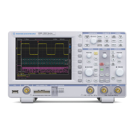
R&S®HMO1002 Series
R&S®HMO1202 Series
Digital Oscilloscope
User Manual
5800530103
Table of
Contents
Previous
Page
Next
Page
1
2
3
4
5
Advertisement
Table of Contents
Need help?
Do you have a question about the HMO1202 Series and is the answer not in the manual?
Ask a question
Questions and answers
Related Manuals for Rohde & Schwarz HMO1202 Series
Test Equipment Rohde & Schwarz HMO1002 Series User Manual
Digital oscilloscope (72 pages)
Test Equipment Rohde & Schwarz HMF2550 Application Manual
Generation and measurement of signals using function generator and programmable counter (9 pages)
Test Equipment Rohde & Schwarz HMO Compact Series User Manual
Digital oscilloscope (19 pages)
Test Equipment Rohde & Schwarz HMO1024 User Manual
Digital oscilloscope (19 pages)
Test Equipment Rohde & Schwarz HMO1524 User Manual
Digital oscilloscope (19 pages)
Test Equipment Rohde & Schwarz HMO2024 User Manual
Digital oscilloscope (19 pages)
Test Equipment Rohde & Schwarz Hameg HMO3524 Manual
(8 pages)
Test Equipment Rohde & Schwarz Hameg HMO3522 Manual
Digital oscilloscope (37 pages)
Test Equipment Rohde & Schwarz HM8123 Application Manual
Generation and measurement of signals using function generator and programmable counter (9 pages)
Test Equipment Rohde & Schwarz HM8134-3 User Manual
1.2 ghz rf-synthesizer (61 pages)
Test Equipment Rohde & Schwarz HAMEG HZ540 User Manual
Near-field probe set (41 pages)
Test Equipment Rohde & Schwarz CMW500 User Manual
Wideband radio communication tester (323 pages)
Test Equipment Rohde & Schwarz RTA4000 User Manual
(861 pages)
Test Equipment Rohde & Schwarz RTP044B Getting Started
High-performance oscilloscope (79 pages)
Test Equipment Rohde & Schwarz RTB2K-72 User Manual
Digital (539 pages)
Test Equipment Rohde & Schwarz RTP044 User Manual
High-performance oscilloscope (2403 pages)
This manual is also suitable for:
Hmo1002 series
Table of Contents
Print
Rename the bookmark
Delete bookmark?
Delete from my manuals?
Login
Sign In
OR
Sign in with Facebook
Sign in with Google
Upload manual
Upload from disk
Upload from URL


Need help?
Do you have a question about the HMO1202 Series and is the answer not in the manual?
Questions and answers