
Subscribe to Our Youtube Channel
Related Manuals for Rohde & Schwarz HAMEG HZ540


Summary of Contents for Rohde & Schwarz HAMEG HZ540
- Page 1 HZ540/HZ550 Near-Field Probe Set Benutzerhandbuch User Manual *5800508202* 5800508202...
- Page 2 A l l g e m e i n e H i n w e i s e z u r C E - K e n n z e i c h n u n g Allgemeine Hinweise zur CE- Kennzeichnung HAMEG Messgeräte erfüllen die Bestimmungen KONFORMITÄTSERKLÄRUNG...
-
Page 3: Table Of Contents
A l l g e m e i n e H i n w e i s e English Für eine korrekte Masseverbindung muss Sorge getragen werden. Bei Signalgeneratoren müssen doppelt abgeschirmte Koaxialkabel (RG223/U, Deutsch RG214/U) verwendet werden. 3. Auswirkungen auf die Geräte Beim Vorliegen starker hochfrequenter elektri- Konformitätserklärung scher oder magnetischer Felder kann es trotz... -
Page 4: Nahfeld-Sonden Hz540 / Hz550
H Z 5 4 0 / H Z 5 5 0 Änderungen vorbehalten... -
Page 5: Technische Daten
T e c h n i s c h e D a t e n E-Feld-Sonde (typischer Frequenzverlauf) SPAN: 3 GHz HZ551 E-Feld-Sonde Frequenzbereich: <1 MHz bis ca. 3 GHz Richtwirkung: Omnidirektional Empfindlich für elektrische Felder Ausgangsimpedanz: 50 Ω; SMA-Anschluss Spannungsversorgung: 6 V / 80 mA HZ552 H-Feld-Sonde RESBW: 30 kHz VIDBW: 100 kHz... -
Page 6: Wichtige Hinweise
W i c h t i g e H i n w e i s e der Lagerung oder des Transports darf die Tem- Wichtige Hinweise peratur zwischen –20 °C und +70 °C betragen. Hat sich während des Transports oder der Lagerung Kondenswasser gebildet, müssen die Messbrücke Sofort nach dem Auspacken sollten die Sonden ca. -
Page 7: Inbetriebnahme
I n b e t r i e b n a h m e elektrischer Kontakt für die Messung im Rahmen Inbetriebnahme der vorgegebenen Grenzwerte vorgesehen. Sicherheitshinweis! Die Spannungsversorgung der Sonden erfolgt di- Grundsätzlich ist die Messung an spannungsführenden Schaltungstei- rekt aus den HAMEG Spektrumanalysatoren. Wird len mit Spannungen höher als 30 V ein anderer Spektrumanalysator, ein Oszilloskop mit den Sonden nicht zulässig. -
Page 8: Allgemeines
A l l g e m e i n e s Schaltungen, Kabeln, Leckstellen in Schirmungen Allgemeines und ähnlichen Störstrahlungsquellen. Die HAMEG Sondensätze HZ540 und HZ550 sind entsprechend der gewünschten Aufgabenstellung unterschied- Entwickler und Hersteller von elektrischen und lich zusammengestellt. elektronischen Geräten sind verpflichtet, die Verträglichkeit der eigenen Geräte im Sinne der Die Sondensätze enthalten in der Basisausstat- EMV-Richtlinie sicherzustellen. - Page 9 A l l g e m e i n e s Einstrahlsonde HZ556 oder in elektrischem Kontakt mit Bauteilean- schlüssen gemessen. Dies ermöglicht die exakt Die Einstrahlsonde HZ556 dient zur Untersuchung Eingrenzung der Störquelle bis hinunter zur der Störempfindlichkeit von analogen – und bedingt Anschlussebene und erlaubt somit die gezielte auch von digitalen Schaltungen. Sie ist passiv Beurteilung getroffener EMV-Maßnahmen.
- Page 10 E M V - P r o b l e m e i n d e r P r a x i s sind solche Sonden zur ersten und überschlä- EMV-Probleme in der Praxis gigen Untersuchung der Wirksamkeit von EMV- Maßnahmen besonders geeignet.
- Page 11 E M V - P r o b l e m e i n d e r P r a x i s tischen Feldes ab und ist damit proportional zur Stromänderung in der Fläche an dieser Stelle. Der zeitliche Ablauf ist recht schnell. Die Flankenzeit liegt im Subnanosekunden- Bereich.
-
Page 12: Emv-Probleme In Der Praxis
E M V - P r o b l e m e i n d e r P r a x i s Signal am Ausgang eines Takttreibers Dies bedeutet, dass der Vcc-Pin über eine Breit- banddrossel an die Vcc-Fläche angeschlossen ist, und außerdem ist diese Fläche aus Gründen der Dämpfung carbonisiert. Man erkennt, dass die Amplitude des Signals in Bild 4 wesentlich kleiner als die in Bild 3 ist. -
Page 13: Praxisorientierte Auswahl Von Signalleitungsfiltern
P r a x i s o r i e n t i e r t e A u s w a h l v o n S i g n a l l e i t u n g s f i l t e r n terscheiden. - Page 14 P r a x i s o r i e n t i e r t e A u s w a h l v o n S i g n a l l e i t u n g s f i l t e r n sungen sind mit der existierenden Ausrüstung schaltungen eine Hochimpedanz-Sonde, die das meist nicht möglich, erforderliche Oszilloskope...
- Page 15 P r a x i s o r i e n t i e r t e A u s w a h l v o n S i g n a l l e i t u n g s f i l t e r n Bild 4 1000 MHz ab. Tatsächlich reicht es noch darüber einen 47Ω-Widerstand. Im Zeitbereich erkennt...
- Page 16 P r a x i s o r i e n t i e r t e A u s w a h l v o n S i g n a l l e i t u n g s f i l t e r n Bild 6 im Vergleich zu Bild 2 kaum eine Veränderung besonders schönes Beispiel für die Wirksamkeit...
-
Page 17: Messung Der Schirmdämpfung Von Abschirmgehäusen
M e s s u n g d e r S c h i r m d ä m p f u n g v o n A b s c h i r m g e h ä u s e n achte: Hier würde eine ausschließliche Betrach- Messung der Schirmdämpfung tung des Zeitbereichs leicht zu völlig falschen... - Page 18 M e s s u n g d e r S c h i r m d ä m p f u n g v o n A b s c h i r m g e h ä u s e n die zugehörigen Linien nirgendwo fehlen. Auch Das Maximum der Störstrahlung liegt im Bereich in sehr ländlichen Bereichen darf heute auch...
- Page 19 M e s s u n g d e r S c h i r m d ä m p f u n g v o n A b s c h i r m g e h ä u s e n Änderungen vorbehalten...
- Page 20 G e n e r a l i n f o r m a t i o n r e g a r d i n g t h e C E m a r k i n g General information regarding the CE marking HAMEG instruments fulfill the regulations of the EMC directive.
- Page 21 C o n t e n t Deutsch This will not cause damage or put the instrument out of operation. Small deviations of the measu- ring value (reading) exceeding the instrument‘s English specifications may result from such conditions in some cases. HAMEG Instruments GmbH General information regarding CE-marking...
-
Page 22: Near Field Probe Hz540 / Hz550
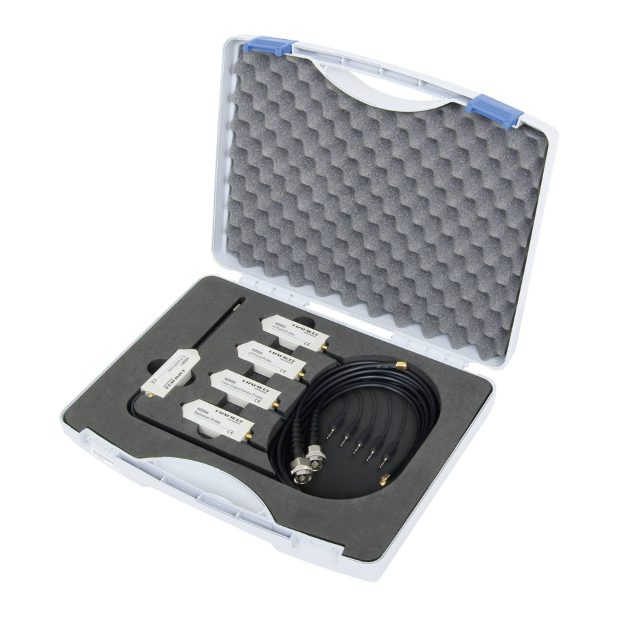
H Z 5 4 0 / H Z 5 5 0 N e a r f i e l d p r o b e s e t H Z 5 4 0 / H Z 5 5 0 Locating radiated emission sources Localisation of EMI sensitive devices Checks on shielding effectiveness Nearfield probe set... -
Page 23: Specifications
S p e c i f i c t i o n s E-Field-Probe Frequency response (typical) SPECIFICATIONS SPAN: 3 GHz Valid at 23 °C after a 30 minutes warm-up period HZ551 Electric Field Probe Frequency range: 1 MHz to approx. 3 GHz Directional sensitivity: Omnidirectional Sensitive to electrical fields Output impedance:... -
Page 24: Important Hints
I m p o r t a n t h i n t s perature may be –20 °C ... +70 °C. The maximum Important hints relative humidity is up to 80%. If condensed water exists in a probe it should be Users are advised to read through these instruc- acclimatized before switching on. -
Page 25: Introduction
I n t r o d u c t i o n Safety notice Introduction Basically, it is not permissible to perform measurements on parts Probe power is supplied directly from HAMEG that are live above 30 V. Since a Spectrum Analyzers. -
Page 26: General
G e n e r a l i n f o r m a t i o n s used to diagnose emissions from circuit boards, General informations integrated circuits, PC board edge runs, ground plane currents, ribbon cables, corner seams and similar interference sources. -
Page 27: Practical Emi Problems
G e n e r a l i n f o r m a t i o n s High Impedance Probe HZ553 Radiation Probe HZ556 The high impedance probe is used to measure The passive probe HZ556 owns the same cha- directly on the com ponent under test or e.g. - Page 28 P r a c t i c a l E M I p r o b l e m s The majority of such probes suffer from a disa- The reason is that the high frequency currents will dvantage: their spatial resolution is very limited. flow mostly close to the V pin as they can only be It is hence difficult to locate the source of the...
- Page 29 P r a c t i c a l E M I p r o b l e m s Signal at clock generator output The last example shows the signal taken from a clock distribution point on a“Europe” size EC board.
-
Page 30: Practical Selection Of Signal-Line Filters
P r a c t i c a l S e l e c t i o n o f S i g n a l - L i n e F i l t e r s this is that the calculated value is referenced to Practical Selection of a capacitive total load. - Page 31 P r a c t i c a l S e l e c t i o n o f S i g n a l - L i n e F i l t e r s sure directly in digital circuits because of this im- operated with a 5MHz frequency.
- Page 32 P r a c t i c a l S e l e c t i o n o f S i g n a l - L i n e F i l t e r s using only time domain measurements is easily Figure 2 shows the results when a 47Ohms re- recognizable: The EMC relevance of a suppression sistor is used. In the time domain a significant...
- Page 33 P r a c t i c a l S e l e c t i o n o f S i g n a l - L i n e F i l t e r s Figure 6 generally poor ground connection of a three-pole which consist of only inductance and capacitance.
-
Page 34: Measurement Of Shielding Attenuation
M e a s u r e m e n t o f S h i e l d i n g A t t e n u a t i o n o f S h i e l d e d H o u s i n g s cellular telephone lines must show the absence of Measurement of the Shielding which would show that the probe has insufficient... - Page 35 M e a s u r e m e n t o f S h i e l d i n g A t t e n u a t i o n o f S h i e l d e d H o u s i n g s Next, the same measurement is performed with the additional shielding around the EUT.
-
Page 36: Commonly Asked Questions
C o m m o n l y a s k e d Q u e s t i o n s Instruments for making compliance measure- Commonly asked questions ments must conform to CISPR 16. This standard about pre-compliance details stringent requirements, and some are emissions testing costly to implement. - Page 37 C o m m o n l y a s k e d Q u e s t i o n s How will the level of ambient signals Do spectrum analyzers have any advan- affect my radiated emissions measure- tages over receivers? ments and will using fully compliant measuring equipment help?
- Page 38 C o m m o n l y a s k e d Q u e s t i o n s Does a spectrum analyzer’s response to pulsed interference influence the measurement result? CISPR 16 contains a curve that defines how quasi- peak detectors respond to a pulsed signal. The curve is based upon the signal’s pulse repetition frequency (PRF).
- Page 39 C o m m o n l y a s k e d Q u e s t i o n s Subject to change without notice...
- Page 40 © 2015 Rohde & Schwarz GmbH & Co. KG Mühldorfstr. 15, 81671 München, Germany Phone: +49 89 41 29 - 0 Fax: +49 89 41 29 12 164 E-mail: info@rohde-schwarz.com Internet: www.rohde-schwarz.com Customer Support: www.customersupport.rohde-schwarz.com Service: www.service.rohde-schwarz.com Subject to change – Data without tolerance limits is not binding. R&S ®...
- Page 41 AlliCE Messtechnik GmbH make ALLICE your partner ALLICE Messtechnik GmbH Kelsterbacher Strasse 15-19 60528 Frankfurt am Main Tel.: +49(0)69-67724-583 Fax: +49(0)69-67724-582 info@allice.de www.allice.de © 2019 Allice Messtechnik GmbH – Alle Rechte vorbehalten. © 2019 Allice Messtechnik GmbH – All rights reserved Verwendete Warenzeichen und Schutzrechte sind Eigentum der jeweiligen Hersteller.
Need help?
Do you have a question about the HAMEG HZ540 and is the answer not in the manual?
Questions and answers