
Related Manuals for Rohde & Schwarz FSH-Z2


Summary of Contents for Rohde & Schwarz FSH-Z2
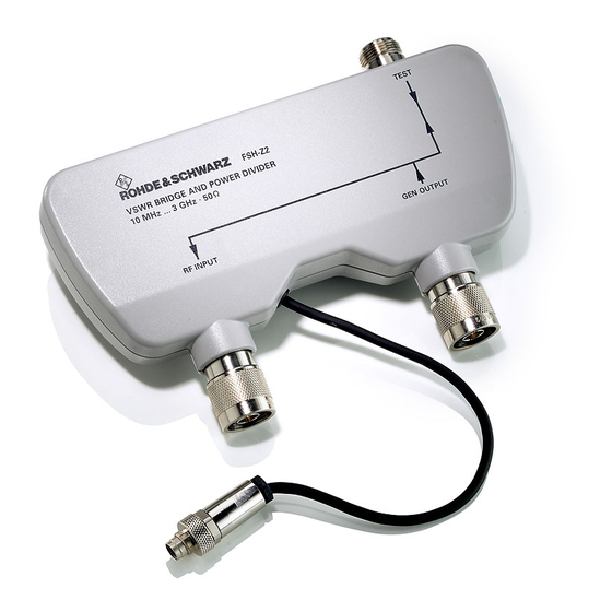
- Page 1 Test and Measurement Division Service Manual VSWR Bridge and Power Divider R&S FSH-Z2 10 MHz to 3 GHz 1145.5767.02 Printed in the Federal Republic of Germany...
-
Page 2: Table Of Contents
R&S FSH-Z2 Contents Contents 1 Performance Test ........................1.1 Test Instructions..........................1.1 Measuring Equipment and Accessories ..................1.1 Performance Test ..........................1.2 Checking the directivity .......................1.2 Checking the Return Loss of the TEST Port................1.3 Performance Test Report.........................1.4 2 Adjustment ............................2.1 3 Repair ..............................3.1 Instrument Design and Functional Description ................3.1 Description of the block diagram ....................3.2... - Page 3 Contents R&S FSH-Z2 4 Documents ..............................4.1 Shipping of Instrument and Ordering of Spare Parts ..............4.1 Shipping of instrument ........................4.1 Shipping of a module ........................4.1 Ordering spare parts ........................4.2 Refurbished modules ........................4.2 Return of defective replaced modules ..................4.2 Spare Parts............................4.3 1145.5767.02...
-
Page 4: Performance Test
R&S FSH-Z2 Test Instructions 1 Performance Test Test Instructions • Values specified in the following sections are not guaranteed. Only the technical specifications provided on the data sheet are binding. • The values specified in the data sheet are the guaranteed limits. -
Page 5: Performance Test
Press softkey [ CONTINUE ] on the Spectrum Analyzer. Replace the Short Circuit termination (item 3) on the "TEST" Port of the R&S FSH-Z2 with the 50 Ohm termination (item 4). The curve shows the directivity (limited by returnloss of the used 50 Ohm termination, item 4). -
Page 6: Checking The Return Loss Of The Test Port
- [ TRANSM CAL : CONTINUE ] Measurment: Connect the two 50 Ohm terminations (item 6) to the ports "GEN OUTPUT" and "RF INPUT" of the R&S FSH-Z2 Remove Short Circuit termination (item 3) from TEST port of the SWR Bridge (item 2). -
Page 7: Performance Test Report
Performance Test Report R&S FSH-Z2 Performance Test Report Table 1-1 Performance Test Report ROHDE & SCHWARZ VSWR Bridge Version 12 12 2003 Model ( ): R&S FSH-Z2 Order number: 1145.5767.02 Serial number: Date: Characteristic Included in Min. value Actual value... -
Page 8: Adjustment
R&S FSH-Z2 Adjustment 2 Adjustment The R&S FSH-Z2 does not have any possibilities for adjustment. 1145.5767.02... -
Page 9: Repair
R&S FSH-Z2 Instrument Design and Functional Description 3 Repair This chapter describes the design of the R&S FSH-Z2, simple measures for repair and troubleshooting, and, in particular, the replacement of parts. Instrument Design and Functional Description The following figure shows a schematic diagram of the R&S FSH-Z2. -
Page 10: Description Of The Block Diagram
Description of the block diagram The R&S FSH-Z2 has two states. In the first state it functions as a SWR bridge. In the second state it functions as a power divider which can be used for Distance To Fault measurements. The R&S FSH-Z2 contains a 5V relay which can be used to switch between the two states. -
Page 11: Spare Part Replacement
Spare Part Replacement Spare Part Replacement This section describes the service concept and contains the spare parts list and the basic documents for the R&S FSH-Z2 instrument. Note: The numbers indicated in brackets refer to items in the mechanical exploded drawings. -
Page 12: Overview Of The Spare Parts
Spare Part Replacement R&S FSH-Z2 Overview of the spare parts Table 3-1 List of spare parts and order numbers Reference Part R&S Order Number Plastic Top/Bottom Cover 01/02/S1 1157.3506.00 Power Cable Assembly (Binder connector) 1157.3512.00 07/10 Coax Cable Assembly 1157.3529.00... -
Page 13: Replacing The Top/Bottom Covers
R&S FSH-Z2 Spare Part Replacement Replacing the Top/Bottom covers Housing parts: 01: Top cover 02: Bottom cover Notes: When replacing the bottom cover, the existing type plate must be placed on the new bottom cover, or the old series number must be written on the new type plate. -
Page 14: Replacing The Power Cable Assembly
Spare Part Replacement R&S FSH-Z2 Replacing the power cable assembly (See exploded view for references). ½ Open the instrument as described earlier. ½ Remove the defective power cable assembly. - Loosen screw (S4) - Remove black shrink sleeve and desolder the two wires from the two pins. - Page 15 R&S FSH-Z2 Spare Part Replacement ½ Fig. 3-9 Mount the grounding wire with soldertag to the unit using screw (S4) ½ Close the instrument as described earlier. 1145.5767.02...
-
Page 16: Replacing The Coax Cable Assembly
Spare Part Replacement R&S FSH-Z2 Replacing the coax cable assembly (See exploded view for references). ½ Open the instrument as described earlier. ½ Fig. 3-10 Connect the coax assy (item 10) to the N-SMA connector (item 07) using a torque wrench ½... -
Page 17: Replacing The N Connector Of The Test Port
R&S FSH-Z2 Spare Part Replacement Replacing the N connector of the TEST Port ½ Open the instrument as described earlier. ½ Loosen the 6 screws (S3) from the metal top cover. ½ Loosen the top two screws (S2) from both N-connectors. -
Page 18: Troubleshooting
This section lists various errors and the suggested corrective action. Troubleshooting problems • Error: Directivity of R&S FSH-Z2 shows a resonance bump at frequencies higher than 2 GHz. Troubleshooting procedure Possible cause of error and further steps Check the N connector of the TEST Port The N connector of the TEST Port is soiled. -
Page 19: Documents
R&S FSH-Z2 Shipping of Instrument and Ordering of Spare Parts 4 Documents This chapter provides information on how to order spare parts, and it also contains the spare parts list. Shipping of Instrument and Ordering of Spare Parts Please contact your Rohde & Schwarz support center or our spare parts express service if you need to request service, repair your equipment, or order spare parts and modules. -
Page 20: Ordering Spare Parts
Shipping of Instrument and Ordering of Spare Parts R&S FSH-Z2 Ordering spare parts To deliver replacement parts promptly and correctly, we need the following information: • R&S order number (refer to the spare part lists in this chapter) • Designation •... -
Page 21: Spare Parts
3 and at the beginning of this serv- ice manual. When shipping a module, be sure to provide sufficient mechanical and antistatic protection. List of R&S FSH-Z2 spare parts The following table lists available spare parts together with their R&S order numbers. Table 4-1 Reference Part R&S Order Number...
Need help?
Do you have a question about the FSH-Z2 and is the answer not in the manual?
Questions and answers