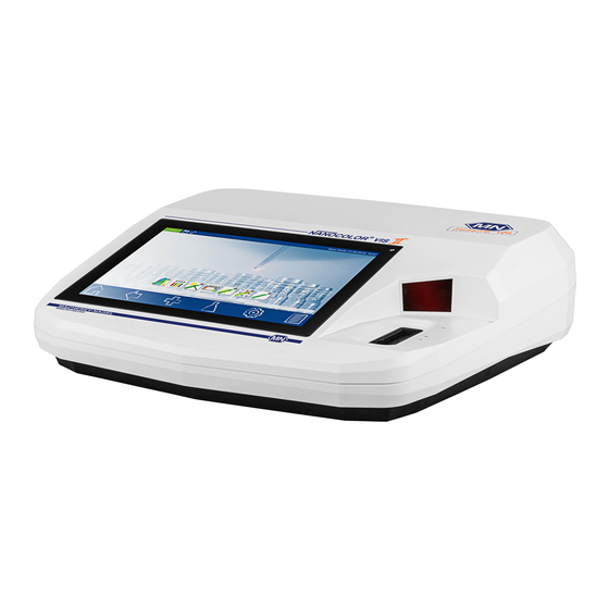
Macherey-Nagel NANOCOLOR UV/VIS II Manual
Water analysis
Hide thumbs
Also See for NANOCOLOR UV/VIS II:
- Quick start manual (33 pages) ,
- User manual (6 pages) ,
- Quick manual (98 pages)
Table of Contents
Advertisement
Quick Links
Advertisement
Table of Contents

Subscribe to Our Youtube Channel
Related Manuals for Macherey-Nagel NANOCOLOR UV/VIS II


Summary of Contents for Macherey-Nagel NANOCOLOR UV/VIS II
-
Page 2: Table Of Contents
Content Content Introduction ............................6 CE mark ............................6 Nameplate ............................6 Explanation of symbols ........................6 Technical description ........................7 Technical details ..........................7 Safety precautions ..........................8 Input supply ............................8 Chemical and biological safety ......................8 Protective clothing ..........................8 Improper handling .......................... - Page 3 Content 5.4.2.3 Calibration ............................32 5.4.2.4 Editing a special method and reporting function ................38 Scan ..............................38 Color measurements ........................40 5.6.1 Color analyis ........................... 41 5.6.1.1 Color references ..........................43 5.6.1.2 DE analysis ............................. 46 5.6.1.3 Preview mode ..........................46 5.6.2 Performing color measurements .....................
- Page 4 Content 6.3.1 Reset............................... 65 6.3.2 Service ............................65 Calibration ............................66 6.4.1 Zero calibration ..........................66 6.4.2 Turbidity calibration ......................... 66 Connectivity ............................ 67 6.5.1 Settings ............................67 6.5.2 RS232 ............................. 68 6.5.3 LAN ..............................68 IQC..............................69 6.6.1 Monitoring of inspection, measuring and test equipment ..............69 6.6.1.1 Lamp check .............................
- Page 5 Content 10.3 Spare parts, accessories and consumables ..................98 10.4 Contact ............................99 10.5 Warranty, liability and complaints ....................99 10.6 Waste disposal ..........................99 ® UV ® NANOCOLOR II and NANOCOLOR VIS II V 1.1 / 10.2017...
-
Page 6: Introduction
Introduction Introduction Welcome and thank you for deciding on a spectrophotometer from MACHEREY-NAGEL.The ® UV ® NANOCOLOR II and NANOCOLOR VIS II are powerful, fast and compact spectrophotometers for water analysis, which are able to evaluate MACHEREY-NAGEL ® NANOCOLOR tube and standard tests. In addition, the instruments are also capable of determining the nephelometric turbidity measuring of a sample by light diffusion at a 90°... -
Page 7: Technical Description
European Community. MACHEREY-NAGEL Identification of the manufacturer Technical description A halogen lamp and a deuterium lamp cover the wavelength range from 190 nm – 1100 nm II. A halogen lamp covers the wavelength range from 320 nm –... -
Page 8: Safety Precautions
Safety precautions Safety precautions Please read the instruction manual carefully before setting up and using the instrument. In case instructions are disregarded, the instrument may malfunction or get damaged. To ensure perfect performance of the instrument, it may only be used as described in this manual. -
Page 9: Damage Of Cable
Please open the shipping box carefully with a sharp tool. Make sure not to damage its contents. Remove the instrument and all other parts carefully. Check the package, instrument and accessories for visible damages. In case a part is damaged, please contact your distributor or MACHEREY-NAGEL’s technical support (see chapter 11.4). ® UV ®... -
Page 10: Outer Appearance
Front and side view The following list contains all items inside the package. Please ensure that your shipment is complete. In case of missing items, please also contact your local distributor or MACHEREY- NAGEL’s technical support. Note: Keep the original box as well as the packaging material from the initial shipment to optimally protect the instrument in case of a return-shipment. -
Page 11: Back View
® The main switch of NANOCOLOR VIS II (Figure 6) can be found on the instrument’s back side. Turn on the instrument. Subsequently, a boot screen appears displaying the MACHEREY-NAGEL logo. Afterwards, the instrument ® UV ® NANOCOLOR II and NANOCOLOR... -
Page 12: Operation And User Guidance
Operation and user guidance performs a self test which takes about one minute. Next, a pop-up informing about the results of the performance check will be displayed. Press to move to the start screen. Now the instrument is ready to use. The instrument’s operating state can be checked in the upper left corner of the display by pressing the status-icon. -
Page 13: Task And Status Bar
Operation and user guidance Figure 9: Text keypad I Press the <-> key to switch between the keypad layouts QWERTZ, QWERTY and AZERTY, depending on which language you are using. Press the 123 / abc key to switch between letters and numbers or special characters. Figure 10: Text keypad II Pressing the ↑... -
Page 14: Favorites Bar
By tapping this icon, one can activate additional features as long as they are available in the selected menu. Test icon: By pressing this icon, basic features as well as MACHEREY-NAGEL tests and applications, such as special methods, scan, color measurement or test number can be selected in the method menu. -
Page 15: Option Buttons And Check Boxes
Operation and user guidance by holding and moving them to the blue colored area. Removal of icons from the favorites bar is done by holding an icon and moving it out of the blue colored area. 4.3.4 Option buttons and check boxes Option buttons are framed in black. -
Page 16: Methods
Basic functions Methods The method selection window can be opened by pressing . The available options are shown in Figure 17. Press the appropriate icon to open the desired window. Figure 17: Method selection window Note: For measurements in the UV-range, please make sure to always cover the cuvette slot. -
Page 17: Absorbance
Basic functions completed, the measurement result will be displayed in the result window (see 6.1.3). In case more samples need to be investigated the next sample can be inserted. Pressing will start the measurement of the next sample. 5.1.3 Absorbance The basic function “Absorbance”... -
Page 18: Transmission
MN tests zero solution and pressing will initiate the zero measurement. After the successful measurement of the zero solution, the sample solution needs to be inserted. Pressing starts the measurement process. A diagram will be displayed showing the live-recording of the measurement results. -
Page 19: Tube Tests
5.2.1 Tube tests MACHEREY-NAGEL tube tests can be selected in different ways with the spectrophotometer. All test tubes are labeled with a barcode. When the start screen is active or the device is in measuring mode, the barcode of the inserted test tube will be scanned automatically. -
Page 20: Retrieving From A List Box
MN tests The "Submethod" entry allows you to change the submethod of the respective method, and thus change the reference unit and the reference value (e.g. PO , see Figure 21). The activated submethod is highlighted in orange. When changing the submethod, the result is automatically converted. -
Page 21: Standard Tests
Figure 23: Filter function in the test list box 5.2.2 Standard tests MACHEREY-NAGEL standard tests can be selected in different ways. It is, however, not possible to select a standard test by barcode identification. The appropriate measurement menu for a specific standard test can be manually selected in the test menu from a list through. -
Page 22: Bio Tests
Procedures for colored or turbid samples solution, the sample solution needs to be inserted. Pressing starts the measurement process. After the measurement has been completed, the measurement result will be displayed in the result window. Via and the icons below the result window, different sample information can be added. - Page 23 Procedures for colored or turbid samples Test Test tube for correction (value B) 0-01 Zirconium Proceed as described in the instructions for Test 0-01, but do not add NANOFIX R2, seal, mix. Procee 0-02, 0-03, 0-04, 0-05, 0-06, d as described in the instructions for test 0-02 / 0-03 / 0-08 Ammonium 3-2000 0-04 / 0-05 / 0-06 / 0-08, but do not add NANOFIX R2, close, mix.
- Page 24 Procedures for colored or turbid samples but add 0.1 mL DMSO instead of 0.1 mL R2. Fill empty test tube with 4.0 mL sample and 0.4 mL 0-54 Copper 7 distilled water, add 0.2 mL R2, close and mix. 0-56 Molybdenum 40 No correction possible.
-
Page 25: Special Methods
5.4.1 Pre-defined methods Pressing the icon will open the list box containing the MACHEREY-NAGEL pre- programmed special methods. The pre-programmed special methods involve important standard analytical methods in the fields of drinking water analysis, brewery analysis and turbidity measurements. For the brewery analysis, MACHEREY-NAGEL provides for the performance of all photometric analysis methods (with the exception of enzymatic testing) in ®... - Page 26 Special methods compliance with MEBAK, Volume II, 2002. Simply select the desired test, insert the required cuvette in the photometer when prompted and read off the measured value. The following table renders a list of the programmed methods for brewery analysis. Method name Reference Anthocyannins acc.
-
Page 27: User Methods
Special methods pressing . The display of the result is similar to the procedure for tube tests and rectangular cuvette tests (see Section 5.2.1). 5.4.2 User methods Pressing the icon opens the submenu for creating and displaying user-defined special methods (see Figure 26). Figure 26: Options for user method creation 5.4.2.1 Lists... - Page 28 Special methods A user-defined special method can be imported into the same type of device via the icon ® UV (Example: The special method from the NANOCOLOR II with the serial number ® UV NUV20001 can be imported into the NANOCOLOR II device with serial number NUV20056).
-
Page 29: Design
Special methods keypad will appear so that you can enter a name for the export file. Entering the desired name and confirming by pressing Enter will save the special method to the external memory. The method can then be imported into a photometer of the same type. Press the icon to edit the selected special method. - Page 30 Special methods Figure 31: Entering the properties of a special method in the single wavelength mode Figure 32: Entering the properties of a special method in the multi-wavelength mode Method name: Enter a method name via the text keypad. The name should not exceed 20 characters in length.
- Page 31 Figure 33: List of possible calculation formulas for multi-wavelength measurements Barcode link: Tap here to open the list of all barcode tests stored in the photometer. In order to retrieve the special method with the barcode of a MACHEREY-NAGEL cuvette, choose the desired test from the list.
-
Page 32: Calibration
Zero link: When the "Barcode link" option is used, the "Zero link" option is enabled. When the corresponding test is selected, the zero stored for the MACHEREY-NAGEL tube test will be used for the calculation. This allows a measurement without a zero solution. This option is available only for the test which was selected in the context of the barcode link and for which a zero is already stored in the photometer. - Page 33 Special methods In the "Enter values" mode, one can create a calibration curve by manually entering the known concentration values and corresponding absorbance value pairs of standard solutions. The "Measure standards" mode enables one to create a calibration table by entering the concentration of the standard solutions and then measuring the corresponding absorbance values.
- Page 34 Special methods Please note: When the “reagent blank value” option is used, the photometer assumes that the corresponding regression line passes through the zero point. If the regression line is supposed to pass through the zero point even when measured against water, please use the option "Zero force“...
- Page 35 Special methods Figure 37: Calibration curve as a result of the measurement of individual standard solutions For linear and quadratic functions, the confidence interval of the statistical calculation is shown as hyperbolas in the form of thin blue lines. (Please note: The factors F0 to F4 are the photometer factors, not the factors of the compensatory function!) The concentration and absorbance pairs appear next to the graph and can be included or excluded by selecting or deselecting the checkbox in front of the pair of values in the analysis.
- Page 36 Special methods For the representation of the confidence interval and statistical data specifications, the accuracy with which the results are calculated can be specified. The confidence level or significance level is set by default to 95%. Figure 39: Setting the confidence level for the regression The values for limit of detection, limit of quantification and detection capability can be viewed and tapping the entry “Statistical data”...
- Page 37 Special methods Figure 41: Re-measuring the sample of the standard series The second method of correcting outliers would be to make a new preparation of the faulty and selecting the option “Repeat measurement” will solution and re-measure it. Pressing open a list box with the various samples (see Figure 41). By selecting the sample to be re- measured and then inserting the sample after being prompted by the photometer, the value in the measurement data will be replaced and the calibration function and statistical data will be re-calculated.
-
Page 38: Editing A Special Method And Reporting Function
Scan section 5.4.2.2). After all the data has been entered and you confirm it by pressing , the calibrated special method will be stored in the list of special methods (see section 5.4.2.1). You will not be able to edit the calibration parameters yourself there, and that’s why they are shown in gray. - Page 39 Scan Figure 44: Scan menu After the successful measurement of the zero solution, the sample solution needs to be inserted. A graphic depicting the wavelengths will appear. The scan of the whole wavelength range can be observed live. After the measurement has been completed, the complete scan will be displayed in the result window.
-
Page 40: Color Measurements
Color measurements memory when the cuvette is removed or when the menu is exited (Please note: This function is only available in the "Open Mode"). Removing the cuvette or exiting the measurement menu by means of other icons in the task bar will end the measuring process and the result will be stored in the measured value memory of the device. -
Page 41: 5.6.1 Color Analyis
Color measurements Figure 47: Result window of the color measurement Various types of sample information are entered using the icons below the result window. icon to view other available options. Via the “Properties” command, new Press the sample information are added below the measurement menu (see Section 5.2.1). The title of the current color measurement is edited using the “Edit Title”... - Page 42 Color measurements Figure 48: Color analysis view Each color measurement is based on a scan from 360 nm to 830 nm. Therefore each color measurement can also be expressed as scan by pressing on the icon . Here the scan can be viewed, zoomed and analysed.
-
Page 43: Color References
Color measurements lightness (brightness). This chromaticity diagram contains (in schematic form) all visible colors. The pure spectral colors (e.g. the color at 560 nm) are on the outer curved boundary of the diagram. The black triangle represents schematically the color gamut of a device using the RGB color space. - Page 44 Color measurements Figure 50: Entering the name of a color reference Choosing the option button “color comparison mode (with ref.) in the color analysis menu can be used to compare a measure color with a stored color reference. Therefore a color measurement from the list in the middle of the color analysis menu as well as a color reference from the list of color references must be choosen.
- Page 45 Color measurements Figure 52: Color comparison using the color measurement menu Confirming with leads to the measurement screen. Inserting a zero followed by insertion of the sample shows the result of the measurement in the result view screen (figure XX). The device automatically evaluates the measurement.
-
Page 46: De Analysis
Color measurements Figure 54: Memory entry of color comparison against color reference 5.6.1.2 DE analysis If your samples show a distribution of color values, e.g. lemonades made of natural fruit juice with seasonal differences in color quality or different origin, you have to determine your color reference from the samples color distribution. -
Page 47: Performing Color Measurements
Color measurements color measutrements into a different color scale. A CIE L+a*b* result e.g. can be also expressed as a APHA/Hazen/PtCo ASTM D 5386 result. 5.6.2 Performing color measurements In the following, the basics of the programmed color measurements of the spectrophotometer and the measurement of colored, translucent samples are described. -
Page 48: Hess-Ives Color Unit
Color measurements 5.6.5.2 Hess-Ives color unit The Hess-Ives color index is calculated as follows from four absorbances at the wavelengths 640 nm, 560 nm, 470 nm and 460 nm according to DGK 0.50.2: (��+��+��)×6 �� − �� = Formula 3 ��... -
Page 49: Saybolt Color Index
Color measurements �� ∆�� = −log ( Formula 10 �� ∆�� = −log ( Formula 11 188,232 The ZERO reference is distilled water. 5.6.6.3 Saybolt color index The Saybolt color index can be applied to all colorations, ranging from -16 (lightest value) to +30 (darkest value) and is measured in 50 mm cuvettes. -
Page 50: Visual Color Scales
Color measurements 5.6.7 Visual color scales The color indexes Hazen / APHA / PtCo, the iodine color index, and the Ph. Eur. color index are defined only visually. The spectrophotometer performs an approximation of the measured CIE-L*a*b* values against a calibration table ("estimate"). 5.6.7.1 Iodine color index The iodine color index measures the color gamut from colorless to yellowish to dark brown... -
Page 51: Characteristics Of The Klett Color Index
Color measurements Figure 57: Ph. Eur. color measurement out of range If the sample is out of range, this will be indicated in the measurement result (see Figure 57). 5.6.9 Characteristics of the Klett color index The Klett color index is one of the oldest photometric color indexes of all. It is measured with an American Klett-Summerson photometer. -
Page 52: Differences Compared To Other Colorimeters
Color measurements ICUMSA sugar color according to ICUMSA Method GS1/3-7, GS2/3-9 and GS2/3-10 Beer color EBC (Analysis Methods for Breweries Vol. 2, EBC 9.4, MEBAK 2.16.2) and ASBC. Hess-Ives according to DGK test method F 050.2 The following colors indexes are calculated from CIE-L*a*b chromaticities: Iodine color index according to DIN 6162 Ph. -
Page 53: Test Number
Test number PtCo/Hazen/ 2° 10, 14, 20, 50 APHA Iodine 2° 10, 14, 20, 50 Gardner 2° Hess-Ives 10, 14, 20, 50 Yellowness index 2° 10, 14, 20, 50 Yellowness index 2°, 10° D65, C 10, 14, 20, 50 E313 Beer color EBC 2°... -
Page 54: Main Menu
Settings Main Menu Press the icon to open the main menu. Now you can choose from the options shown in Figure 59. Figure 59: Main menu Settings In this menu, general settings for the instrument can be made or options which affect the measurement process can be selected. -
Page 55: Language
Settings 6.1.1 Language Click on the icon to select the language of the instrument from the list that pops up. After you have selected the desired language, the list will close and the chosen language will be applied as the general display language for the entire device. 6.1.2 Region Click on the... -
Page 56: Memory Settings
Settings Figure 62: Settings for the date and time display format Press the button to open the date and time settings window (Figure 63). Press the arrow button to set the desired date and time. Confirming with the button saves the settings. A preview of the date and time display can be seen in the lower left hand corner of the pop-up window. -
Page 57: Acoustic Signal
Settings Figure 64: Memory settings The automatic saving of all measurement results can be switched on or off using the “Save measurement results” checkbox. If the box is unchecked, all of the measurement results will be displayed but not saved. Please note: The option for switching off the measurement results memory is only available in the “Open Mode”... -
Page 58: Printer
A printer can be connected directly to the spectrophotometer via the two USB A ports. In addition to standard printer models (Please note: PCL6 protocol must be supported.) MACHEREY-NAGEL also offers thermal printers for the connection to the spectrophotometers. The check box "color printing" is only relevant for printers that support color printing. -
Page 59: Reaction Time
Settings Figure 67: Activate “Remember sample place” 6.1.8 Reaction time Press the icon to open a window to turn on this function. When turned on, the reaction time stored for a test will begin to count down automatically before the measurement. After the reaction time has counted down, the measurement will then take place automatically. -
Page 60: Ntu Check
Settings lamp is indicated by a popup window, showing the warm up time. Activation of the deuterium lamp is indicated by the "UV" flag in the status bar of the device. The maximum service life of the deuterium lamp is 1000 hours on average. Adjusting the lamp change point controls the use of the UV lamp in the wavelength range from 335 nm-345 nm. -
Page 61: Sipper
Settings Figure 70: Activate “NTU-Check” function 6.1.11 Sipper Press the icon to open the window for the sipper pump settings. When a sipper pump is connected, the settings made here for pump time, flush time and delay time will be applied. To connect the sipper pump to the spectrophotometer, please consult Section 6.5.1 and observe the instructions in the sipper manual. -
Page 62: Dilution Format
Settings memory card, the backup can be stored on an external USB drive. Select the desired storage medium via the option buttons (see Figure 72). When the button is pressed, the photometer data will be backed up to the selected storage medium. The message “Backup complete” confirms that the backup process was successful. -
Page 63: Power Saving Mode
System Figure 73: Choose dilution format 6.1.14 Power saving mode Press the icon to open a window for activating this function (Figure 74). This is where you set the time for the display to switch off when not in use in order to save energy. Simply tap on the black display in the energy saving mode to switch it back on and start using the instrument. -
Page 64: System Info
(Figure 76). This is where information on the manufacturer, instrument model, serial number, operating system version, software and firmware version, and the number of system starts are listed. Please have this information ready when contacting the MACHEREY-NAGEL technical support. Figure 76: System info 6.2.2... -
Page 65: Update
USB drive. Download the update file from the MACHEREY-NAGEL homepage and extract the ZIP file on your PC. Copy the .mns update file to the top level of a USB stick and connect it to the ... -
Page 66: Calibration
Calibration Calibration The spectrophotometer performs a self-test each time it starts to check the basic calibration. The basic calibration or zero calibration as well as the calibration of the nephelometric turbidity measurement can be performed manually, if required, via the calibration menu. Figure 78: Calibration menu 6.4.1 Zero calibration... -
Page 67: Connectivity
Connectivity Figure 79: Turbidity calibration Connectivity In the connectivity menu, settings are made for the interfaces RS232, LAN and USB which the instrument provides. Figure 80: Connectivity menu 6.5.1 Settings In the connectivity settings (see Figure 81) the various types of interfaces on the device can be controlled. -
Page 68: Rs232
Connectivity Figure 81: Connectivity settings 6.5.2 RS232 In the RS232 settings (see Figure 82) the baud rate, bits and parity can be set. Tap on the respective text field to open a list box with the available settings. Confirm with to save the settings. -
Page 69: Iqc
Figure 83: Overview of the LAN settings The menu for internal quality control (IQC) is activated by pressing the icon and it contains the options shown in Figure 84. The various options make it possible to model the internal quality control document. Even though the limits for standard measurements, multiple determinations, dilution series, and spike additions that are stored in the menu are based on German requirements, they can always be changed by the user. -
Page 70: Lamp Check
Figure 85: Options of inspection equipment monitoring 6.6.1.1 Lamp check The lamp check serves to ensure that the installed lamp(s) are working properly. When you ® UV press the icon on the NANOCOLOR II, a window will open with a selection of the lamps to check (see Figure 86). -
Page 71: Nanocheck
The NANOCHECK program is used to check the photometric accuracy of the spectrophotometer. For this purpose, you will need the NANOCONTROL NANOCHECK test solutions (REF 925 701) offered by MACHEREY-NAGEL. Press the icon to open the NANOCHECK program menu (see Figure 87). In order to enter the wavelength, reference value, and confidence interval data from the product certificate, each field must be manually selected and the corresponding value entered via the alphanumeric keypad. -
Page 72: Wavelength Accuracy Test
Figure 88: Running the NANOCHECK program After all test solutions have been measured, the measured values will be displayed in the evaluation table to the right of the respective wavelength (see Figure 89). If the value falls within the confidence interval, it will be displayed in green, otherwise the value will be displayed in red and the entire measurement will be given a “Failed”... -
Page 73: Stray Light Test
beam path. Press the icon to open the program for the wavelength accuracy test. Confirm with to start the automatic measuring process. After testing, the result of the measurement will be displayed (see Figure 90). The actual values are compared against the reference values stored for the built-in holium oxide filter. -
Page 74: Standard Measurement
The result of the measurement will be displayed upon completion of the test. For each wavelength, the mean detector value I and the standard deviation of the scattering of detector values are given. Furthermore, the largest absolute difference between two values is given as . - Page 75 Figure 92: Result of a standard measurement Various types of sample information can be entered using the icons located below the result icon to view other available options. Via the “Properties” command, window. Press the new sample information can be added below the measurement menu (see Section 5.2.1). The “Do not save”...
- Page 76 icon must be pressed in the “Select In order to enter a user-defined standard, the standard” dynamic list (see Figure 94). Figure 94: Selecting a standard A text keypad will pop up for entering the name of the user-defined standard. After the first measurement with the self-defined standard, the name entered here will appear in the dynamic list for standard selection along with the test number and test name (see Figure 94 “User defined Standard”...
-
Page 77: Multiple Determination
keypad and confirm with to open the measurement window. After inserting the appropriate sample solution and confirming with , the measurement will be carried out and the result will be displayed as shown in Figure 92. The user-defined standard will not be saved in the list of standards until the measurement has been carried out. - Page 78 Figure 97: Measurement process of a multiple determination After inserting and measuring all of the sample solutions, the result of the measurement will be displayed as shown in Figure 98. The result will be given the rating “Passed” (green) or “Failed”...
-
Page 79: Dilution Series
Removing the cuvette or exiting the measurement menu by means of one of the other icons in the task bar will end the measurement process and save the result in the IQC memory (see Section 6.6.7) of the device. 6.6.4 Dilution series Through the analysis of a dilution series, interferences or problems with the sample can be sought and detected. -
Page 80: Spike Additions
Figure 100: Result of the dilution series measurement In the example above, the measured value of the diluted sample is 14.5 mg/L. The dilution factor of a 1+1 dilution is two. The expected value can be calculated as 29.0 mg/L. Based on the measured value of the undiluted sample with 29.7 mg/L, this means an absolute deviation of -0.6 mg/L. - Page 81 sample through the standard addition. Enter the confidence interval of the expected value in the “Confidence interval” field using the alphanumeric keypad. Enter the LOT for test kit and standard on the alphanumeric keypad and confirm with open the measurement window. The user-defined standard will not be saved in the list of standards until the measurement has been carried out.
-
Page 82: Iqc Counter
In the sample above, the measured value of the sample is 14.5 mg/L. The measured value of the spiked sample is 29.8 mg/L. Therefore, the increase in concentration due to the spike addition is 15.3 mg/L. When compared to the expected value of 15.0 mg/L at the permissible confidence level of 10%, a deviation is not detected;... - Page 83 Figure 104: Overview of the measurements in the IQC memory You have the option of printing the results, exporting them as CSV- or PNG file or deleting them (Please note: Deleting results in the user mode is only available when administrator rights are given”).
-
Page 84: Iqc Card 4
Results can be send to a directly connected printer, or can be exported as PNG-file to an external storage device and then be printed from another workstation. When measurement results are printed or exported as PNG-file, the print-out will contain a selection of the most important information on the sample or all information available on the sample, depending on the chosen print settings (see Section 6.1.6). - Page 85 By tapping on the desired entry, all of the IQC measurements belonging to this standard will be compiled in a standard control card (see Figure 108). Figure 108: IQC 4 control card The middle green line reflects the reference value of the standard. The upper and lower red lines indicate the limits of the confidence interval of the standard.
-
Page 86: User Accounts
User accounts User accounts The spectrophotometer allows a user management system with the creation of multiple user accounts with various rights. The instrument is delivered in the Open Mode by default. There are no limitations to user rights in this mode. To switch to the User Mode, first a user account has to be created. - Page 87 User accounts Figure 111: Creating an user account Press the icon to edit the settings for a user (see Figutre 110). In User Mode, a user account can only be edited by someone with administrator privileges. Press the icon to delete a highlighted user. Following the confirmation prompt, the user will be deleted from the list.
-
Page 88: Pictograms
If the key is being shown, then the user has administrator privileges. Pictograms To facilitate the use of MACHEREY-NAGEL tube tests, the pictograms on the lids of test packs are stored in the instrument. This way the procedure can be tracked directly on the device and is always at hand. -
Page 89: Data Export
Data export Press the icon to open the list of the MACHEREY-NAGEL tube tests. Select the test from this list for which you want to display the pictogram. The last pictogram to be retrieved will be shown on the display. (Please note: Pictograms are not available for all of the tube tests). -
Page 90: Acron
In order to export to ACRON, this menu contains the settings for changing the data export to a format adapted to ACRON. For more information on transferring data to ACRON is available through the technical support of MACHEREY-NAGEL. 6.10 Tools The menu with tools can be accessed via the main menu followed by choosing the icon. -
Page 91: Timer
Tools 6.10.1 Timer The spectrophotometer has an integrated timer function (see Figure 118). The buttons can be used to set any time in the format hh/mm/ss. By pressing the button , you can stop or start the countdown. Press the button to reset the time. -
Page 92: Memory
Tools MACHEREY-NAGEL tube test boxes have a 2D barcode on the back, which contains the LOT number of the test. When pressing the barcode icon in the LOT tracking menu, the 2D barcode scanner will become active and the 2D barcode from the box can be scanned. Test name, test numer, LOT number and expiration date are automatically entered into the list in the LOT tracking menu. - Page 93 Tools Figure 121). In addition to the type of measurement (method, scan, absorbance, etc.), the result of the measurement is also shown. Whenever the measurement memory is retrieved, the measurement results of the past month are pre-selected. Figure 121: Measurement memory display with options buttons can be used to browse through the individual pages of the memory.
-
Page 94: Memory Selection
Memory selection The information obtained in this way can be printed, deleted or exported again. In the case of a scan and a kinetics measurement, a detailed view of the spectrum or the evaluation diagram is shown. Furthermore, in case of a color measurement or a scan, press to open the respective menu for the color or scan analysis (see also Section 5.6.1 and 5.5). -
Page 95: Printing From The Memory
Export to ACRON For the export to ACRON, a special data format is provided. For more information on transferring data to ACRON pleases contact the technical support of MACHEREY-NAGEL. Deletion of memory It is possible to delete the entire memory, individual results or a selection of results. Please note: Deleting information from the device memory is legitimized only in the "Open Mode"... -
Page 96: Background Images
USB storage medium. You can delete the list entry by pressing and holding down the list entry for several seconds and then confirming with the icon (see Figure 126). Please note: MACHEREY-NAGEL recommends the use of widescreen images with a resolution of 1280 x 800 pixels. Figure 126: Removing a wallpaper The wallpaper can be defined separately for each user in User Mode. -
Page 97: Avatars
USB storage medium. You can delete the list entry by pressing and holding down the list entry for several seconds and then confirming with the icon. Please note: MACHEREY-NAGEL recommends the use of images with a resolution of 180 x 180 pixels. Connection of External Devices Printer An external printer can be connected to the spectrophotometer via the two USB A ports. -
Page 98: Cleaning The Display
Spare parts, accessories and consumables 10.2.1 Cleaning the display Clean the display using the special display cleaning cloth included with delivery. Please do not use any glass cleaner. Wipe off any excess moisture immediately. Avoid scratching the display. Please do not use ballpoint pens or other sharp objects to operate the touchscreen. The touchscreen can be operated with the accompanying touchpen or any other touchpen suitable for PCAP displays. -
Page 99: Contact
Dispose of according to Directive 2012/19/EU (WEEE). In agreement with the European Directive 2012/19/EU on waste electrical and electronic equipment (WEEE), MACHEREY-NAGEL will take back the old equipment and dispose of it free of charge. Please note: It is prohibited to dispose of the device through public waste disposal systems.
Need help?
Do you have a question about the NANOCOLOR UV/VIS II and is the answer not in the manual?
Questions and answers
i want to prove the trecability for the MN manufacture calibration curve anr recomendation for update this curve
To prove the traceability for the Macherey-Nagel UV/VIS II calibration curve, use standard solutions of known concentrations. You can either:
1. Manually enter known concentration and absorbance value pairs in "Enter values" mode.
2. Enter concentrations and measure absorbance values in "Measure standards" mode.
In both cases, a calibration curve is generated, and statistical data with a calibration function (up to 4th degree) is calculated and displayed, ensuring traceability.
For updating the calibration curve, ensure all method data is entered before measurement. Export user-defined methods to an external storage medium (e.g., USB) before updates. Avoid turning off the device during the update and restart it after completion.
This answer is automatically generated