Table of Contents
Advertisement
Quick Links
Download this manual
See also:
User Manual
Envertech EVT248 Quick Installation Guide
Please read and follow the
safety andinstallation instructions belo
w. You can find
and download this instructions or
other technical documents on our web
site:
http://www.envertec.com
or call us by: 400-666-5819
Components
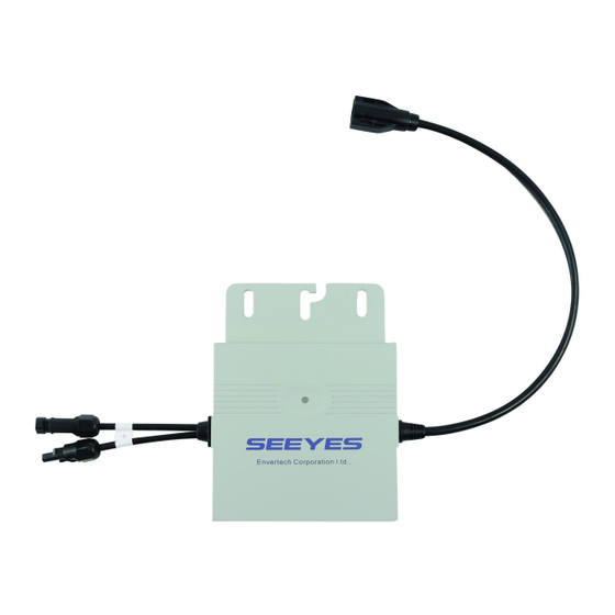
Microinverter
Monitoring Device
EnverBridge
EVT248
Three wires cable:
Live wire (Brown)
Neutral wire (Blue)
AC Bus
P/E wire (Green & Yellow)
Cable
Distance between T-
connector is 1.05m(41"),
2.1m (83")
Three wires cable. To
AC Extension
connect the AC junction box
to the grid. Three wires
Cable (Optional)
cable: 2.5mm
-4mm
2
AC Trunk
To protect the unused T-
Connector of bus cable
Plug Cap
AC Trunk
To Protect the end cut of
bus cable
End Cap
To unplug the branch
AC Trunk
cable from the T-
Unlock Tool
Connector and bus cable.
Select The AC Bus Cable
To install the AC bus cable, you just simply unroll the cable to the needed length
to make the cut. Directly connect the AC bus cable to the junction box of the
branch. Seal the other cutting end with the end cap to make it isolated from the
environment. You should choose the type of AC bus cable according to the
orientation of PV module. We suggest the following type of cable:
The longitudinal
ENVERTECH
ENVERTECH
ENVERTECH
1.05m
1.05m
Envertech EVT248 Microinverter Installation
Installation could only be implemented when
the system disconnected from the grid, and
the solar panel has been covered or
disconnected.
1.
Position Bus Cable
Please make sure that the microinverter connected in each branch are less than 20
sets.
Run AC bus cable along
the racking system
2.
Fasten AC Bus Cable To The Rack
Fasten AC bus cable and
ground cable to the rack
with cable ties
3.
Fix The Microinverter To The Rack
Fix the microinverter to the rack at the appropriate location of bus cable
connectors. You can mark the location of the bus cable connectors on the rack.
Fix the microinverters
on the back side of panel
to avoid sunlight and rain
(Keep the logo face down)
EnverPortal
http://www.envertecportal.com
2
The transverse
ENVERTECH
ENVERTECH
ENVERTECH
2.1m
2.1m
Cable tie
ENVERTECH
4.
Grounding
Both PV modules and microinverters should be connected to the ground according to
the regulation of safety.
Use screw(M6) to fix the
ground cable terminal at
the grounding mark of
microinverter
Notice: T-connector of bus cable should be located within the range of the
microinverter
5.
Connect The AC Cable
A.
Remove the AC trunk plug caps from bus cable connectors
and connect microinverters;
B.
Fitting the plug caps to unused connectors to keep them
water tight.
A
6.
Seal The Cutting End Of AC Bus Cable
A.
Remove the cover of wire for 25mm;
B.
Check if all the parts of connector are inside. Screw the nuts
on the cable, set the lock ring and seal ring at the wire end;
C.
Plug the sealed wire end into the hole to isolate each wire
with others;
D.
Screw the nut to the seal ring with torque of 2.5 Nm.
A
C
7.
Connect The Trunk Cable To The Junction Box
Connect the trunk cable to
the AC junction box
8.
Mount EnverBridge
Option 1: Fix EnverBridge in the house
distribution box
1. (Dangerous !) Turn off the air switch and
connect the socket. This operation should be
done under the instructions of
professionals;
2.Fix EnverBridge at proper position in or
close to the distribution box;
3.Open the cover on the right side of
EnverBridge. Set RJ45 cable through the
water proof connect or and connect it to the
EnverBridge. Close the cover and recheck if
it's completely sealed;
4. Run the RJ45 cableand connect it to your
router5.Plug the EnverBridge on the
socket;
Option 2: Fix EnverBridge inside the house
1. Open the cover on the right side of
EnverBridge. Set RJ45 cable through the
water proof connect or and connect it to the
EnverBridge. Close the cover and recheck if
it's completely sealed;
2. Run the RJ45 cable and connect it to your
router;
3. Fix EnverBridge at proper position in or
close to the distribution box;
4. (Dangerous !) Turn off the air switch and
connect the EnverBridge to it. This operation
should be done under the instructions of
professionals;
Option 3: Mount Enverbridge outside of the
house
1. Open the cover on the right side of
EnverBridge. Set RJ45 cable through the
water proof connector and connect it to the
EnverBridge. Close the cover and recheck if
it's completely sealed;
2. Run the RJ45 cable and connect it to your
router;
3. Fix the EnverBridge on the rack (Refer to
the installation of Microinverter);
4.Connect the power cable to the T-
Connector of trunk cable;
Prepare AC Extension Cable
9.
You can order AC Extension Cable from Envertech, or from any other stores. 25mm
or 44mm
cable suggested.
2
A.
Remove the external cover of cable by y=40mm and cover of wire by
x=14mm. Set the metal connector on the wire and clamp to fix the
connection;
B.
Connect the extension cable to the junction box;
ENVERTECH
B
B
D
2
Advertisement
Table of Contents

Subscribe to Our Youtube Channel
Summary of Contents for Envertech EVT248
- Page 1 Fix the microinverter to the rack at the appropriate location of bus cable connectors. You can mark the location of the bus cable connectors on the rack. You can order AC Extension Cable from Envertech, or from any other stores. 25mm or 44mm cable suggested.
- Page 2 Connect PV Module To Microinverter Connect the PV module to the DC inputof microinverter Click my power plant and fill in the information of EnverBridge; ENVERTECH Switch On The System After confirm all the connection are completed, switch on the system. Monitoring Through EnverPortal Visit http:www.envertecportal.com;...


Need help?
Do you have a question about the EVT248 and is the answer not in the manual?
Questions and answers