Table of Contents
Advertisement
Quick Links
Media
Media
Converter
Converter
Q
I
uick
nstallation
I N D U S T R I A L
Introduction
The
IMC-V111ET-TB
is a cost-effective solution for extending an Ethernet
connection beyond its inherent distance limitation.
extend the distance to 2,400 meters using 26AWG cable. It has a switching
architecture with 1 RJ-45 100Mbps Ethernet port and one asymmetric or
symmetric Ethernet over VDSL2 port which is a terminal block connector
supports 2-wired transmission.
IMC-V111ET-TB
o
temperature range from -40~75 C, making it suitable for harsh operating
environments.
Package Contents
The series is shipped with the following items. If any of these items is missing
or damaged, please contact your customer service representative for
assistance.
Contents
Pictures
Number
IMC-V111ET-TB
DIN-rail Kit
Wall-mount Kit
QIG
4-pin terminal block
Preparation
Before installation, make sure you have all of the package contents
available.
Safety & Warnings
Elevated Operating Ambient:
If installed in a closed cabinet, the operating
ambient temperature of the rack environment may be greater than room ambient.
Therefore, consideration should be given to installing the equipment in an
environment compatible with the maximum ambient temperature (Tma) specified
by the manufacturer.
Reduced Air Flow:
Installation of the equipment should be such that the
amount of air flow required for safe operation of the equipment is not
compromised.
Mechanical Loading:
Mounting of the equipment in the d
such that a hazardous condition is not achieved due to uneven mechanical
loading.
Circuit Overloading:
Consideration should be given to the connection of the
equipment to the supply circuit and the effect that overloading of the circuits
might have on overcurrent protection and supply wiring. Appropriate
consideration of equipment nameplate ratings should be used when addressing
this concern.
Q I G
IMC-V111ET-TB
G
uide
Dimension (Unit: mm)
IMC-V111ET-TB
can
provides a wide operating
P1
P2
IMC-V111ET-TB
CPE
LNK/ACT
CO
2
Line
Mode
CO
Inter.
Sym.
9db
LNK/ACT
1
ETH
100M
X 1
41.0
X 1
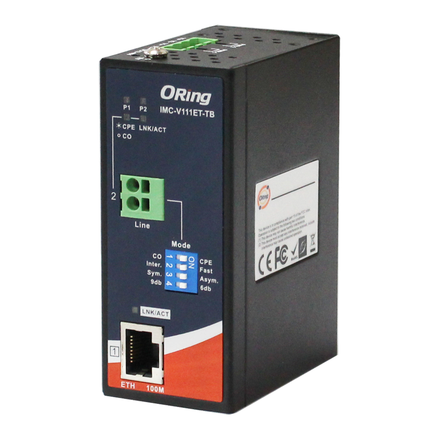
Panel Layouts
X 2
Front Panel
2
X 1
1
IMC-V111ET-TB
P1
P2
3
4
CPE
LNK/ACT
CO
X 1
5
2
Line
CO
6
Inter.
Sym.
9db
7
LNK/ACT
8
1
ETH
100M
Top Panel
in-rail
should be
1
2
1907-2-29-IMCV111ETTB-1.0
IMC-V111ET-TB
22.6
22.0
20.0
28.0
13.1
70.0
41
20.0
14.0
13.5
CPE
Fast
Asym.
6db
1. PWR1 LED
2. PWR2 LED
3. CEP mode LED
4. LNK/ACT LED for extension port
5. Extension port
6. DIP switch for mode selection
7. LNK/ACT LED for LAN port
8. LAN Port
Mode
CPE
Fast
Asym.
6db
Real Panel
1. Din-rail screw holes
1. Wall-mount screw
holes
2. Terminal block
1
PRINTED ON RECYCLED PAPER
Industrial Extended Media Converter
Installation
DIN-rail Installation
Step 1:
Slant the switch and screw the Din-rail kit onto the back of the switch, right in the
middle of the back panel.
Step 2:
Slide the switch onto a DIN-rail from the Din-rail kit and make sure the switch clicks into
the rail firmly.
40.0
Wall-mounting
Step 1:
Screw the two pieces of wall-mount kits onto both sides of the switch. A
total of eight screws are required, as shown below.
Step 2:
Use the switch, with wall mount plates attached, as a guide to mark the correct
locations of the four screws.
Step 3:
Insert four screw heads through the large parts of the keyhole-shaped apertures, and
then slide the switch downwards. Tighten the four screws for added stability.
Version 1.0
P1
P2
IMC-V111ET-TB
CPE
LNK/ACT
CO
2
Line
Mode
CO
CPE
Inter.
Fast
Sym.
Asym.
9db
6db
LNK/ACT
1
ETH
100M
Quick Installation Guide
Advertisement
Table of Contents

Related Manuals for ORiNG IMC-V111ET-TB

Summary of Contents for ORiNG IMC-V111ET-TB
- Page 1 Version 1.0 Media Media IMC-V111ET-TB Industrial Extended Media Converter Converter Converter uick nstallation uide I N D U S T R I A L Introduction Installation Dimension (Unit: mm) IMC-V111ET-TB is a cost-effective solution for extending an Ethernet DIN-rail Installation connection beyond its inherent distance limitation.
- Page 2 FCC Part 15, CISPR (EN55022) class A front of the terminal block connector. All rights reserved. EN61000-4-2 (ESD), EN61000-4-3 (RS), EN61000-4-4 (EFT), EN61000-4-5 (Surge),EN61000-4-6 (CS), EN61000-4-8, EN61000-4-11 Shock IEC60068-2-27 ORing Industrial Networking Corp. Free Fall IEC60068-2-32 TEL: +886-2-2218-1066 Website: www.oring-networking.com FAX: +886-2-2218-1014 E-mail: support@oring-networking.com...
Need help?
Do you have a question about the IMC-V111ET-TB and is the answer not in the manual?
Questions and answers