Table of Contents
Advertisement
Quick Links
Advertisement
Table of Contents

Related Manuals for Leader LV 7380


Summary of Contents for Leader LV 7380
- Page 1 LV 7380 MULTI SDI RASTERIZER LV 7380SER01 3D ASSIST INSTRUCTION MANUAL...
-
Page 2: Table Of Contents
TABLE OF CONTENTS GENERAL SAFETY SUMMARY ..................I INTRODUCTION ......................1 Scope of Warranty ........................1 Operating Precautions ......................1 1.2.1 Maximum Allowable Input Voltage ................... 1 1.2.2 Shorting and Applying External Input to the Output Connectors........2 1.2.3 Backup Battery ........................ 2 1.2.4 Mechanical Shock...................... - Page 3 BEFORE YOU BEGIN MEASURING ............... 24 About the Power Supply ....................... 24 4.1.1 Applying DC Power......................24 4.1.2 Turning the Power On....................24 4.1.3 Turning the Power Off....................24 Connecting to a Display ......................25 SDI Signal Input ........................26 SDI Signal Output .........................
- Page 4 8.2.3 Deleting Display Mode Presets..................70 Copying Presets........................71 8.3.1 Copying All Presets from USB Memory to the LV 7380 ..........71 8.3.2 Copying All Presets from the LV 7380 to USB Memory ..........71 SCREEN CAPTURE FEATURE ................72 Taking a Screen Capture of the Display................
- Page 5 10.1 Video Signal Waveform Display Explanation ................ 76 10.2 Setting the Display Position ....................77 10.2.1 Setting the Horizontal Position..................77 10.2.2 Setting the Vertical Position ................... 77 10.3 Selecting Which Channels to Display ................... 78 10.4 Setting the Display Mode ...................... 78 10.5 Configuring the Video Signal Waveform and Scale Settings..........
- Page 6 11.1 Vector Display Explanation ....................99 11.2 Configuring Vector and Scale Settings................100 11.2.1 Turning the Display of the I and Q Axes On and Off ............ 100 11.2.2 Selecting the Scale Color .................... 101 11.2.3 Selecting the Vector Color ................... 101 11.2.4 Selecting the Contrast ....................
- Page 7 12.7.7 Turning the Display of the Safe Title Marker On and Off..........120 12.7.8 Turning the Display of User Markers On and Off ............120 12.7.9 Setting User Markers ....................121 12.8 Configuring Line Selection Settings ..................122 12.8.1 Turning Line Selection On and Off................122 12.8.2 Selecting Lines ......................
- Page 8 13.5.5 Adjusting the Lissajous Curve Intensity ............... 151 13.5.6 Adjusting the Scale Intensity..................152 13.6 Configuring Surround Display Settings ................152 13.6.1 Selecting the Display Format ..................152 13.6.2 Setting the Gain ......................153 13.6.3 Mapping Channels....................... 153 13.6.4 Adjusting the Surround Waveform Intensity..............154 13.6.5 Adjusting the Scale Intensity..................
- Page 9 14.8.1 Displaying EDH Packets ....................174 14.8.2 Displaying the Format ID ..................... 175 14.8.3 Displaying Audio Control Packets ................176 14.8.4 Displaying Closed Caption Packets ................177 14.8.5 Displaying the Inter-Stationary Control Signal ............. 178 14.8.6 Displaying the Data Broadcast Trigger Signal.............. 180 14.8.7 Displaying User Data ....................
- Page 10 16.1.9 Capture Menu ......................247 16.2 CHANGE HISTORY OF THE SOFTWARE................. 248 Index...
-
Page 11: General Safety Summary
■ Note about Reading This Manual The contents of this manual contain specialized terminology and may be difficult to understand. If you have any questions about the contents of this manual, please contact your local LEADER agent. ■ Symbols and Terms The following symbols and terms are used in this instruction manual and on the instrument to indicate important warnings and notes. - Page 12 GENERAL SAFETY SUMMARY Read the warnings and information below thoroughly to avoid death, personal injury, and damage and deterioration of the instrument. ■ Warnings Concerning the Case and Panels Do not remove the instrument's case or panels for any reason. Touching the internal components of the instrument could lead to fire or electric shock.
- Page 13 Failing to do so could lead to fire. Turn off the power switch, and remove the AC adapter from the instrument. After making sure that fire has not spread anywhere, contact your local LEADER agent. ■...
- Page 14 To ensure stable performance, we recommend that you have the instrument calibrated regularly. Also, if the instrument malfunctions, repairs are necessary. For repairs and calibration, contact your local LEADER agent. ■ Routine Maintenance When you clean the instrument, remove the power plug.
-
Page 15: Introduction
1. INTRODUCTION INTRODUCTION Thank you for purchasing this LEADER instrument. To use this instrument safely, read this instruction manual thoroughly, and make sure that you know how to use the instrument properly. If some point about the operation of this instrument is still unclear after you have read this instruction manual, refer to the contact information on the back cover of the manual to contact LEADER, or contact your local LEADER agent. -
Page 16: Shorting And Applying External Input To The Output Connectors
• The contents of all presets are deleted. To continually use these features, we recommend that you replace the backup battery with a new one every five years after you purchase the LV 7380. Also, save the presets to USB memory. -
Page 17: Specifications
Two Serial Digital Inputs and Outputs The LV 7380 is equipped with two SDI inputs. This enables the LV 7380 to receive two different SDI signals and to receive a single signal in dual link mode. The LV 7380 can also generate a serial reclocked SDI signal for each SDI signal that it receives. - Page 18 The display can be captured and stored as still-image data. Not only can captured data be displayed by the LV 7380, but it can also be compared with an input signal or saved to USB memory as bitmap data. The saved bitmap data can then be viewed on a PC.
- Page 19 ● Last Memory The LV 7380 backs up the current settings so that you can use the same settings that were previously in use immediately after powering the instrument up. ● External Remote Control Connector Presets can be loaded from the external remote control connector.
-
Page 20: Specifications
3D Assist Option (LV 7380SER01, requires a license key) The LV 7380 makes it possible to perform 3D video signal evaluation on the signals that it receives: the video signal for the left eye and the video signal for the right eye separately as well as side-by-side signals or top-and-bottom signals, which contain the video signals for both eyes. -
Page 21: Audio Playback
2. SPECIFICATIONS Format Settings Link Format Switching Manually switched between single and dual link Format Setting Single Link Automatic or manual switching Dual Link Manual switching. Only frame and field rates can be set automatically. When these signals are displayed, phase differences of up to 100 clocks (approx. 1.4 μs) between links A and B are automatically corrected. -
Page 22: Control Connectors
Used to save screen captures, event logs, preset data, and data dumps Ethernet Port Compliant Standard IEEE 802.3 Supported Protocols TELNET, FTP, SNMP Input/Output Connector RJ-45 Function Used to control the LV 7380 from a PC and monitor errors and other events Type 10Base-T/100Base-TX... -
Page 23: Screen Capture
Data Output Screen captures can be saved as bitmap files to USB memory, or they can be saved in a file format that the LV 7380 can load. Data Input Data saved to USB memory can be loaded and displayed on the LV 7380. -
Page 24: Display Formats
2.3.7 Display Formats Display Format XGA (effective resolution: 1024 × 768). In 16:9 and 16:10 modes, the LV 7380 output can be displayed on 16:9 and 16:10 LCD panels, respectively. (Only if the LCD panel has a resolution conversion feature). -
Page 25: Vector Display
2. SPECIFICATIONS HD Frequency Characteristics Y Signal ≤ ±0.5 % for 1 to 30 MHz Signals ≤ ±0.5 % for 0.5 to 15 MHz Low-Pass Attenuation ≥ 20 dB (at 20 MHz) SD Frequency Characteristics Y Signal ≤ ±0.5 % for 1 to 5.75 MHz Signals ≤... -
Page 26: Bar Display
2. SPECIFICATIONS On the multi-screen display, the blanking period depends on the video signal waveform display's blanking display settings. 2.3.10 5 Bar Display Function Displays the peak levels of Y, R, G, B and composite Channel Assignment RGB, GBR Scale mV, % Error Level Based on gamut error level, composite gamut error... - Page 27 CRC Error Detection Counts the number of times that the input signal's CRC value and the CRC value recalculated by the LV 7380 differ Code Violation Detection Counts the number of times that the state of the input signal's biphase modulation is abnormal...
-
Page 28: Status Display
2. SPECIFICATIONS 2.3.13 Status Display Signal Detection Detects the presence of an SDI signal Format Display Detected using the supported video format signals (Only the frame rate is detected when the link format is set to dual.) Embedded Audio Channel Displays the embedded audio channel number (Only link A is supported when the link format is set to dual.) -
Page 29: Error Detection
2. SPECIFICATIONS 2.3.14 Error Detection Error Count Up to 999999 errors for each error type Count Period All errors that occur in one field are counted as one error Video Errors CRC Error Detects HD-SDI signal transmission errors EDH Error Detects SD-SDI signal transmission errors TRS Error Detects TRS location and protection bit errors... -
Page 30: Ancillary Data Analysis
2. SPECIFICATIONS 2.3.15 Ancillary Data Analysis Audio Control Packet (Only for link A when the link format is set to dual) Display Details Displays audio control packet analysis Display Formats Text, hexadecimal, binary Group Selection Select one group from four available groups. EDH Display (Only for SD-SDI) Compliant Standard SMPTE RP-165... -
Page 31: Ancillary Data List Display
Last Memory Backs up the panel settings. Key Lock Use the key lock feature to prevent accidental operations on the LV 7380. SHORT CUT Key Press this key to recall preset settings with a single... -
Page 32: Options
2. SPECIFICATIONS key press (you can only recall settings for one display). This key can also be used to take screen captures and save captures to USB memory with a single key press. 2.3.22 Options Eye Pattern Display Option LV 58SER02 (factory option) (Eye pattern and jitter displays;... - Page 33 2. SPECIFICATIONS the video signal for the right eye Flicker Display Displays the video signal for the left eye and the video signal for the right eye on a time sharing display Inverted Display Horizontal Inversion Inverts the picture and video signal waveform (*1) Vertical Inversion Inverts the picture Inverted Channel...
-
Page 34: General Specifications
2. SPECIFICATIONS 2.3.23 General Specifications Environmental Conditions Operating Temperature Range 0 to 40 °C Operating Humidity Range 85 %RH or less (no condensation) Optimal Temperature 10 to 30 °C Power Requirements Voltage 10 to 18 VDC Power Consumption 50 W max. Dimensions 426 (W) ×... -
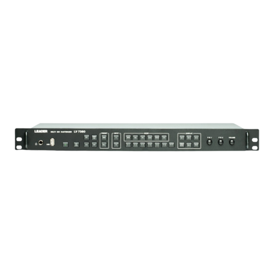
Page 35: Names And Functions Of Parts
3. NAMES AND FUNCTIONS OF PARTS NAMES AND FUNCTIONS OF PARTS Front Panel Figure 3-1 Front panel Table 3-1 Front panel items and functions Name Function Power switch A quick push switches the power from off to on. Holding the switch switches the power from on to off. See section 4.1, “About the Power Supply.”... - Page 36 3. NAMES AND FUNCTIONS OF PARTS Name Function Switches to the video signal waveform display. See chapter 10, “VIDEO SIGNAL WAVEFORM DISPLAY.” Switches to the vector display. See chapter 11, “VECTOR DISPLAY.” Switches to the picture display. See chapter 12, “PICTURE DISPLAY.” AUDIO Switches to the audio display.
-
Page 37: Rear Panel
See section 4.6, “External Sync Signal Input.” DVI-I OUTPUT DVI-I connector for connecting a display. ETHERNET Ethernet connector for controlling the LV 7380 panel operations over TELNET, FTP, or SNMP. See section 15.2, “TELNET” and section 15.3, “SNMP.” REMOTE Remote control connector used to perform operations such as loading presets. -
Page 38: Before You Begin Measuring
When the LV 7380 is connected to the DC power supply, the internal microcomputer is in standby mode, and some power is consumed even if the power switch is turned off. If you do not intend to use the LV 7380 for an extended period of time, disconnect the DC power supply. -
Page 39: Connecting To A Display
By connecting a display to the DVI-I output connector, you can display a variety of screens. Using a DVI-I cable, connect the LV 7380 to an XGA (1024 × 768) display. (The display and the cable are not included with the LV 7380.) The DVI-I output connector supports both serial digital output (Single Link TMDS) and RGB analog output. -
Page 40: Sdi Signal Input
Standards.” You can switch between single link and dual link in the system settings. For single link, the LV 7380, by default, automatically detects the input format. For dual link or to set the input format manually, use the system settings. -
Page 41: Aes/Ebu Signal I/O
AES MODE setting on the audio menu to switch the connector functions. By setting EXT AES MODE to INPUT and MONITOR SELECT to EXT AES, you can use the LV 7380 to measure the AES/EBU signals that are received through the AES/EBU I/O connectors. - Page 42 The formats in which waveforms can be displayed while using a black burst signal as the sync signal are listed below. If the external sync signal is an NTSC black burst signal with an embedded 10-field ID and the SDI signal is 1080PsF/23.98 or 1080p/23.98, the LV 7380 automatically recognizes the 10-field ID.
-
Page 43: Enabling And Releasing The Key Lock
Enabling and Releasing the Key Lock You can prevent accidental operations on the LV 7380 by enabling the key lock. The key lock disables all LV 7380 keys except for the power switch. Remote control and Ethernet control are not affected. -
Page 44: General Display Explanation
Key Lock Indication This symbol appears when the key lock is enabled. Hold down KEY LOCK to enable or release the key lock. USB Indication This symbol appears when USB memory is connected to the LV 7380. - Page 45 • FAN ALARM This alarm appears when the fan is not functioning. If “FAN ALARM” appears, immediately turn the power off, and then contact your local LEADER agent. • OVER HEAT This alarm appears when the internal temperature has exceeded the specified limits.
-
Page 46: Explanation Of Key Operations
4. BEFORE YOU BEGIN MEASURING 4.10 Explanation of Key Operations 4.10.1 Menu Operations Use the function menu at the bottom of the screen to change the settings. Use the F•1 to F•7 keys and the F•D 1, F•D 2, and VOLUME knobs on the front panel to operate the function menu. -
Page 47: Tab Menu Operations
4. BEFORE YOU BEGIN MEASURING 4.10.2 Tab Menu Operations You can usually use the function menu to change the settings, but some settings appear on tab menus. Figure 4-9 Tab menu The list below explains how to perform different operations on the tab menu. •... -
Page 48: System Settings
It takes approximately 20 seconds to switch between the dual link and single link formats. While the LV 7380 is switching from one link format to the other, it displays the message, “System reconfiguration.”... - Page 49 5. SYSTEM SETTINGS • i/PsF Select Select whether the following input format names are displayed as interlaced or as segmented frame when Format Select is set to Auto. • 1080i/60 and 1080PsF/30 • 1080i/59.94 and 1080PsF/29.97 • 1080i/50 and 1080PsF/25 Settings Interlace: The input format name is displayed as interlaced (this is the...
-
Page 50: Configuring Dual Link Settings
5. SYSTEM SETTINGS Select the scanning, and then select the frame (field) rate. The formats that you can select are shown in the table below. Table 5-1 Manual settings for single link format Scanning Frame (Field) Rates 1080i 60 / 59.94 / 50 1080PsF 30 / 29.97 / 25 / 24 / 23.98 1080P... -
Page 51: Configuring The External Interface
5. SYSTEM SETTINGS Configuring the External Interface To configure the remote control connector and the Ethernet port, follow the procedure below. These settings can not be registered to presets. Procedure SYS → F•2 INTERFACE 5.2.1 Configuring the Remote Control Connector To configure the remote control connector, use the REMOTE SETUP tab. -
Page 52: Configuring The Ethernet Port
LV 7380. Figure 5-5 ETHERNET SETUP tab • Network Select Select the method that you want to use to connect the LV 7380 to an Ethernet. This setting is enabled after you restart the LV 7380. Settings... -
Page 53: Setting The Aspect Ratio
SYS → F•3 DISPLAY → F•1 ASPECT SELECT Settings 4:3: The LV 7380 produces a signal for a 4:3 display (this is the default value). 16:9: For vectors, pictures, and audio waveforms, the LV 7380 generates a signal for a 16:9 display. -
Page 54: Setting Ids
5. SYSTEM SETTINGS Setting IDs The LV 7380 can display user-defined IDs for the input channels. To display IDs, follow the procedure below. SYS → F•3 DISPLAY → F•3 ID NAME → F•1 SDI Ach or F•2 SDI Bch The following screen, for creating the ID, appears. -
Page 55: Configuring The Display
5. SYSTEM SETTINGS Configuring the Display To configure the display, access F•4 INFORMATION on the system menu. You can use this menu to set the display format of the timecode, error counter, input format, and input signal. 5.5.1 Setting the Timecode Display Format To select the display format for the timecode that is embedded in the input signal, follow the procedure below. -
Page 56: Setting The Input Channel Display Format
To set the date and time, follow the procedure below. The settings that you specify here will not be initialized even if you initialize the LV 7380. To set the date, select the appropriate item, and then turn F•D 1 DATE SET. -
Page 57: Configuring License Settings
To use an option that requires a license, you must enter the appropriate license key. A license key is a key code that activates an option on the LV 7380. LEADER will send you a license key when you purchase an option. Before purchasing an option, prepare the MAC address(*1) and the serial number(*2) of your LV 7380. -
Page 58: Viewing The Mac Address And Options
To remove an installed option, enter the license key, and then press F•6 REMOVE. 5.8.2 Viewing the MAC Address and Options On the license display shown above, you can view the MAC address and the options that are installed on the LV 7380. Initialization 5.9.1 Initializing Settings To initialize the settings to their default values, follow the procedure below. -
Page 59: Multi-Screen Display Feature
6. MULTI-SCREEN DISPLAY FEATURE MULTI-SCREEN DISPLAY FEATURE The LV 7380 has six display modes: picture display, video signal waveform display, vector display, audio display, status display, and eye pattern display (optional). The display that only shows one mode at a time is referred to as the single-screen display.(*1) The display that shows combinations of different modes at the same time is referred to as the multi-screen display. -
Page 60: Selecting The Display Mode
3D ASSIST: The Video signal for the left eye and the video signal for the right eye are displayed simultaneously. You cannot select this setting when the LV 7380 is in dual link mode or when the input is SD. -
Page 61: Selecting The Multi-Screen Display Format
6. MULTI-SCREEN DISPLAY FEATURE INPUT MODE = 3D ASSIST (option) Figure 6-2 Selecting the display mode Selecting the Multi-Screen Display Format When F•1 INPUT MODE is set to SINGLE or DUAL, follow the procedure below to select the display format of the multi-screen display. Procedure MULTI →... - Page 62 6. MULTI-SCREEN DISPLAY FEATURE DISPLAY MODE = P+W+V DISPLAY MODE = P+W+V+A DISPLAY MODE = QUAD Figure 6-3 Multi-display formats (1-channel display) • 2-Channel Display (DUAL) Settings P+W:H: The picture and video-signal-waveform displays of channels A and B are arranged horizontally (this is the default value). P+W:V: The picture and video-signal-waveform displays of channels A and B are arranged vertically.
- Page 63 6. MULTI-SCREEN DISPLAY FEATURE DISPLAY MODE = P+W:H DISPLAY MODE = P+W:V DISPLAY MODE = W+V:V DISPLAY MODE = WFM+PIC (option) DISPLAY MODE = VEC+PIC (option) Figure 6-4 Multi-display formats (2-channel display)
-
Page 64: Setting The Quad-Screen Display
6. MULTI-SCREEN DISPLAY FEATURE Setting the Quad-Screen Display In the single input display, when F•2 DISPLAY MODE is set to QUAD, to assign display modes to the different areas of the screen, follow the procedure below. If you assign the same display mode to multiple areas, all the areas except for the one with the smallest area number will have their display modes cleared. -
Page 65: Switching Between The Video Signal Waveform And Histogram Sub Items
6. MULTI-SCREEN DISPLAY FEATURE WFM WIPE = ON WFM WIPE = OFF Figure 6-5 Wipe display Switching between the Video Signal Waveform and Histogram Sub Items In the single input display, when F•2 DISPLAY MODE is set to PIC+WFM1 or PIC+WFM2 or in the 3D assist display (option), when F•3 MEASURE SELECT is not set to DISPRTY, to switch the video signal waveform to a histogram, follow the procedure below. -
Page 66: Setting The Histogram
6. MULTI-SCREEN DISPLAY FEATURE Setting the Histogram When F•4 SUB-ITEM is set to HISTOGRAM, press F•5 HISTOGRAM SETUP to configure the histogram settings. 6.7.1 Selecting the Display Format To select the histogram display format, follow the procedure below. Procedure MULTI → F•5 HISTOGRAM SETUP → F•1 HISTOGRAM FORM Settings LUMA: The histogram of the Y (luminance) signal is displayed. -
Page 67: Setting The Measurement Mode
6. MULTI-SCREEN DISPLAY FEATURE Setting the Measurement Mode To set a measurement mode from the multi-screen display, follow the procedure below. For details about a particular measurement mode's menu, see the appropriate measurement mode explanation (the explanations start at chapter 10). Generally, changing the settings here will also change the single-screen display settings. -
Page 68: D Assist Display Feature (Option)
7. 3D ASSIST DISPLAY FEATURE (OPTION) 3D ASSIST DISPLAY FEATURE (OPTION) This chapter explains the 3D assist display feature, which is activated when you set F•1 INPUT MODE to 3D ASSIST in the multi-screen display feature. The 3D assist display is an option. To use it, you need the LV 7380SER01, which is sold separately. -
Page 69: Selecting The Display Format
7. 3D ASSIST DISPLAY FEATURE (OPTION) Top-and-bottom signal 3D INPUT FORMAT = TOP&BOTM Figure 7-1 Selecting the input signal Selecting the Display Format To select the picture display format, follow the procedure below. By using anaglyph glasses with the anaglyph displays (AGLPH CL and AGLPH MO), you can easily check 3D video signals. -
Page 70: Configuring Checkerboard Display Settings
7. 3D ASSIST DISPLAY FEATURE (OPTION) PICTURE FORM = AGLPH CL / AGLPH MO PICTURE FORM = CNVRGNCE PICTURE FORM = OVERLAY PICTURE FORM = CHECKER (*1) PICTURE FORM = WIPE (*1) PICTURE FORM = FLICKER Figure 7-2 Selecting the display format To make this explanation clearer, the video signal for the right eye has been replaced with a different signal. -
Page 71: Configuring Wipe Display Settings
7. 3D ASSIST DISPLAY FEATURE (OPTION) Configuring Wipe Display Settings When F•1 PICTURE FORM is set to WIPE, use the 3D FUNCTION menu to configure the boundary line settings. 7.4.1 Turning the Boundary Lines On and Off To turn the boundary lines on and off, follow the procedure below. Procedure MULTI →... -
Page 72: Selecting The Measurement Mode
7. 3D ASSIST DISPLAY FEATURE (OPTION) Selecting the Measurement Mode When F•1 PICTURE FORM is set to AGLPH CL, AGLPH MO, CNVRGNCE, or OVERLAY, you can use the grid or the cursors to measure disparity. To select the disparity measurement mode, follow the procedure below. Procedure MULTI →... -
Page 73: Selecting The Grid To Configure
7. 3D ASSIST DISPLAY FEATURE (OPTION) GRID DISPLAY = DISPRTY GRID DISPLAY = HORIZONT Figure 7-4 Selecting the displayed grid 7.7.2 Selecting the Grid to Configure Configure the disparity grid and the horizontal grid separately. When F•1 GRID DISPLAY is set to BOTH, to select the grid that you want to configure, follow the procedure below. -
Page 74: Selecting The Grid Line Adjustment Unit
7. 3D ASSIST DISPLAY FEATURE (OPTION) 7.7.4 Selecting the Grid Line Adjustment Unit To select the grid adjustment unit, follow the procedure below. Procedure MULTI → F•2 3D FUNCTION → F•4 GRID SETUP → F•3 GRID UNIT Settings PIX,LINE: The disparity grid lines are adjusted with pixels as the unit. The horizontal grid lines are adjusted with lines as the unit (this is the default value). -
Page 75: Configuring Disparity Measurement Settings
7. 3D ASSIST DISPLAY FEATURE (OPTION) Configuring Disparity Measurement Settings When F•3 MEASURE SELECT is set to DISPRTY, press F•4 DISPRTY SETUP to measure disparity. 7.8.1 Disparity Measurement Display Explanation Figure 7-5 Disparity measurement display V cursor This is the vertical cursor. L cursor This is a disparity measurement cursor. - Page 76 This displays the viewing environment that has been configured on the PARAMETER display. • About the Names of Settings and Measurement Items The names of the settings and measurement items that are used with the LV 7380 are shown below. Figure 7-6 Setting and measurement item names...
-
Page 77: Disparity Measurement Procedure
7. 3D ASSIST DISPLAY FEATURE (OPTION) 7.8.2 Disparity Measurement Procedure To measure disparity, follow the procedure below. Before you begin this procedure, set F•3 MEASURE SELECT to DISPRTY on the 3D FUNCTION menu. Press F•4 DISPRTY SETUP and then F•1 SETUP. The PARAMETER display appears. -
Page 78: Configuring Video Signal Waveform Settings
7. 3D ASSIST DISPLAY FEATURE (OPTION) Press F•1 COMPLETE. The settings are confirmed, and the disparity measurement display appears. To cancel the settings, press F•7 CANCEL. Figure 7-8 Disparity measurement display Set F•2 CURSOR SELECT to L/R. Turn F•D 1 LEFT POS to match the L cursor with the video signal for the left eye. Press F•D 1 to move the cursor to approximately the center of the screen. -
Page 79: Selecting The Display Format
7. 3D ASSIST DISPLAY FEATURE (OPTION) 7.9.1 Selecting the Display Format To select the video signal waveform display format, follow the procedure below. Procedure MULTI → F•5 WFM SETUP → F•1 WFM FORM Settings ALIGN: Channel A (the video signal for the left eye) and channel B (the video signal for the right eye) are displayed side by side (this is the default value). -
Page 80: Preset Feature
You can register up to 30 different sets of all the panel settings (some settings are not included).(*1) Registering Presets Set the LV 7380 to the settings that you want to register, and then press MEM. Press F•1 FULL PRESET on the preset registration menu to register the settings. Loading Presets Set FUNCTION PRESET to OFF on the preset registration menu. -
Page 81: Preset Settings
8. PRESET FEATURE Preset Settings 8.1.1 Registering Presets Set the LV 7380 to the settings that you want to register. Press MEM. The preset registration menu appears. Press F•1 FULL PRESET. A list of files appears. Press F•2 COMMENT INPUT. -
Page 82: Loading Presets
8. PRESET FEATURE 8.1.2 Loading Presets To load presets, you have to set FUNCTION PRESET to OFF by following the procedure below. The default value of FUNCTION PRESET is OFF. When the multi-screen display is being used, regardless of the FUNCTION PRESET setting, pressing RCLL displays the preset menu. -
Page 83: Display Mode Presets
8. PRESET FEATURE Display Mode Presets 8.2.1 Registering Display Mode Presets Set the LV 7380 to the settings that you want to register. Press MEM. The preset registration menu appears. Press F•2 FUNCTION PRESET. A list of files appears. F•2 FUNCTION PRESET appears on the single-screen display. -
Page 84: Loading Display Mode Presets
8. PRESET FEATURE 8.2.2 Loading Display Mode Presets To load display mode presets, you have to set FUNCTION PRESET to ON by following the procedure below. The default value of FUNCTION PRESET is OFF. Press MEM. The preset registration menu appears. Press F•2 FUNCTION PRESET. -
Page 85: Copying Presets
8.3.1 Copying All Presets from USB Memory to the LV 7380 To copy all of the presets that have been saved to USB memory to the LV 7380, follow the procedure below. If presets have already been saved to the LV 7380 memory, they will be overwritten. -
Page 86: Screen Capture Feature
You can use the screen capture feature to acquire still image data of the current display. You can save the acquired data to USB memory or overlay it on the input signal and display it using the LV 7380. Take a screen capture See section 8.1, “Taking a... -
Page 87: Taking A Screen Capture Of The Display
Display,” is cleared when operations such as changing the display mode are performed. You can display the captured data on the LV 7380 even after the power has been turned off by saving the captured data to USB memory (if you save the captured data in BSW format). -
Page 88: Displaying Screen Capture Data
Displaying Screen Capture Data The data that you capture by following the procedure in section 9.1, “Taking a Screen Capture of the Display,” can be displayed on the LV 7380, or it can be overlaid on the LV 7380's current input signal. -
Page 89: Displaying Screen Capture Data Saved To Usb Memory
Displaying Screen Capture Data Saved to USB Memory The data that you save in BSW format by following the procedure in section 9.2, “Saving Screen Capture Data,” can be displayed on the LV 7380, or it can be overlaid on the LV 7380's current input signal. -
Page 90: 10. Video Signal Waveform Display
10. VIDEO SIGNAL WAVEFORM DISPLAY 10. VIDEO SIGNAL WAVEFORM DISPLAY 10.1 Video Signal Waveform Display Explanation To display video signal waveforms, press WFM. Figure 10-1 Video signal waveform display Error Counter The error counter, the current time, and the elapsed time appear here. Gain The video signal waveform gain appears here. -
Page 91: Setting The Display Position
10. VIDEO SIGNAL WAVEFORM DISPLAY Display Format The video signal waveform display format (YCbCr, GBR, YGBR, RGB, YRGB, or COMPOSITE) appears here. Filter FILTER LPF appears here when FILTER has been set to LOW PASS. Thumbnail (Audio meter) The audio meter appears here as a thumbnail. You can also turn this off. Thumbnail (Picture) The picture appears here as a thumbnail. -
Page 92: Selecting Which Channels To Display
10. VIDEO SIGNAL WAVEFORM DISPLAY 10.3 Selecting Which Channels to Display Pressing a front panel key from CH 1 to CH 3 turns on or off the display of the video signal waveform assigned to that key. The video signal waveform display is on when a key is lit and off when the key is not lit. -
Page 93: Configuring The Video Signal Waveform And Scale Settings
10. VIDEO SIGNAL WAVEFORM DISPLAY 10.5 Configuring the Video Signal Waveform and Scale Settings To configure video-signal-waveform and scale settings, press F•1 INTEN/SCALE on the video signal waveform menu. 10.5.1 Selecting the Scale Unit To set the scale units, follow the procedure below. Regardless of this setting, when COLOR MATRIX is set to COMPOSIT, the scale units will always be % when the composite display format is NTSC and V when the composite display format is PAL. -
Page 94: Selecting The Scale Color
10. VIDEO SIGNAL WAVEFORM DISPLAY SCALE UNIT = 3FF Figure 10-3 Scale units 10.5.2 Selecting the Scale Color To select the scale color from one of seven options, follow the procedure below. Procedure WFM → F•1 INTEN/SCALE → F•2 SCALE COLOR Settings WHITE: The scale is displayed in white. -
Page 95: Displaying Markers For 75 % Intensity Color Bars
10. VIDEO SIGNAL WAVEFORM DISPLAY 10.5.4 Displaying Markers for 75 % Intensity Color Bars When a 75% color bar signal is being input, to display markers that correspond to the chrominance signal peak levels, follow the procedure below. This setting is available when COLOR MATRIX is set to YCbCr. For information on the COLOR MATRIX setting, see section 10.10.1, “Selecting the Display Format.”... -
Page 96: Selecting The Contrast
10. VIDEO SIGNAL WAVEFORM DISPLAY USER MARKER = DUAL Figure 10-5 Displaying user markers 10.5.6 Selecting the Contrast To select the video signal waveform contrast, follow the procedure below. If the video signal waveform is displayed simultaneously with the vector waveform on the multi-screen display, the contrast will be the same as the vector waveform contrast. -
Page 97: Adjusting The Scale Intensity
10. VIDEO SIGNAL WAVEFORM DISPLAY 10.5.8 Adjusting the Scale Intensity To set the scale intensity, follow the procedure below. If you press F•D 2, the intensity will be set to its default value of 4. Procedure WFM → F•1 INTEN/SCALE → F•D 2 SCALE INTEN Settings Range: -8 to 7 (the default value is 4) -
Page 98: Selecting The Vertical Display Position
10. VIDEO SIGNAL WAVEFORM DISPLAY GAIN MAG = ×1 GAIN MAG = ×5 GAIN VARIABLE = 0.750 GAIN VARIABLE = 2.500 Figure 10-6 Vertical gain 10.6.3 Selecting the Vertical Display Position When F•2 GAIN MAG is set to ×5, to select the vertical display position, follow the procedure below. -
Page 99: Selecting The Filter
10. VIDEO SIGNAL WAVEFORM DISPLAY 10.6.4 Selecting the Filter To select the filter, follow the procedure below. The filters that you can select vary depending on how COLOR MATRIX is set. For information on the COLOR MATRIX setting, see section 10.10.1, “Selecting the Display Format.” Procedure WFM →... -
Page 100: Configuring Sweep Settings
10. VIDEO SIGNAL WAVEFORM DISPLAY FILTER = LUM+CRMA Figure 10-9 Pseudo-composite signal filters 10.7 Configuring Sweep Settings To configure the sweep settings, press F•3 SWEEP on the video signal waveform menu. 10.7.1 Selecting the Sweep Method To select the video signal waveform sweep method, follow the procedure below. Procedure WFM →... -
Page 101: Selecting The Field Or Frame Display Format
10. VIDEO SIGNAL WAVEFORM DISPLAY H SWEEP = H H SWEEP = 1H H SWEEP = 2H Figure 10-10 Selecting the line display format 10.7.3 Selecting the Field or Frame Display Format When F•1 SWEEP is set to V, to select the field or frame display format, follow the procedure below. -
Page 102: Selecting The Horizontal Magnification
10. VIDEO SIGNAL WAVEFORM DISPLAY 10.7.4 Selecting the Horizontal Magnification To select the horizontal magnification, follow the procedure below. The magnifications that you can select vary as indicated below depending on the F•1 SWEEP and F•2 H SWEEP, COLOR MATRIX settings. (The table cells marked with “Yes” represent settings that can be selected.) For information on the COLOR MATRIX setting, see section 10.10.1, “Selecting the Display Format.”... -
Page 103: Selecting The Field To Display
10. VIDEO SIGNAL WAVEFORM DISPLAY SWEEP MAG = ACTIVE SWEEP MAG = BLANK Figure 10-12 Horizontal magnifications 10.7.5 Selecting the Field to Display When the input signal is interlace or segmented frame and F•2 V SWEEP is set to 1V, to select which field is displayed, follow the procedure below. -
Page 104: Configuring Line Selection Settings
10. VIDEO SIGNAL WAVEFORM DISPLAY BLANKING = REMOVE BLANKING = ALL VIEW Figure 10-13 Displaying blanking intervals 10.8 Configuring Line Selection Settings To configure the line selection settings, press F•4 LINE SEL on the video signal waveform menu. You can display the waveforms of the selected line. The line selection display cannot be used on the field, frame, 2-channel, or 3D assist displays (option). -
Page 105: Selecting Lines
10. VIDEO SIGNAL WAVEFORM DISPLAY 10.8.2 Selecting Lines To select a line to display the waveform of, follow the procedure below. The selected line is indicated in the lower left of the screen. If you press F•D 1, the selected line changes to the first video line. -
Page 106: Moving Cursors
10. VIDEO SIGNAL WAVEFORM DISPLAY CURSOR = X CURSOR = Y Figure 10-15 Cursor types 10.9.2 Moving Cursors To move the cursors, follow the procedure below. Setting F•3 FD VAR TRACK and pressing F•D 1 changes the same setting. • To Move Each Cursor Separately (The default value) Move the REF (blue) cursor with F•D 1 REF, and move the DELTA (green) cursor with F•D 2 DELTA. -
Page 107: Selecting The Measurement Unit
10. VIDEO SIGNAL WAVEFORM DISPLAY 10.9.3 Selecting the Measurement Unit To change the units used in cursor measurements, follow the procedure below. • When CURSOR Is Set to Y Procedure WFM → F•5 CURSOR → F•2 Y UNIT Settings Measurements are made in units of voltage (this is the default value). Measurements are made as percentages. -
Page 108: 10.10 Configuring The Color System Settings
10. VIDEO SIGNAL WAVEFORM DISPLAY 10.10 Configuring the Color System Settings To configure the color system settings, press F•6 COLOR SYSTEM on the video signal waveform menu. 10.10.1 Selecting the Display Format To select the video signal waveform display format, follow the procedure below. The selected display format is indicated in the upper right of the display. -
Page 109: Displaying Luminance Signals And Gbr Signals Simultaneously
10. VIDEO SIGNAL WAVEFORM DISPLAY 10.10.2 Displaying Luminance Signals and GBR Signals Simultaneously To display the GBR or RGB signal simultaneously with the luminance signal, follow the procedure below. The selected display format is indicated in the upper right of the display. This setting is available when F•1 COLOR MATRIX is set to GBR or RGB. -
Page 110: Setting The Composite Display Format
10. VIDEO SIGNAL WAVEFORM DISPLAY RGB = ON RGB = OFF Figure 10-18 RGB display 10.10.4 Setting the Composite Display Format To select the format for the pseudo-composite display, follow the procedure shown below. Changing this setting will also change the format setting for the vector display. Procedure WFM →... -
Page 111: 10.11 Configuring Thumbnail Settings
10. VIDEO SIGNAL WAVEFORM DISPLAY 10.11 Configuring Thumbnail Settings To configure the thumbnail settings, press F•7 THUMBNAIL on the video signal waveform menu. 10.11.1 Turning the Audio Meter Display On and Off To display the audio meter on the video signal waveform display, follow the procedure below. -
Page 112: Turning The Picture Display On And Off
10. VIDEO SIGNAL WAVEFORM DISPLAY LAYOUT = HORIZ1 LAYOUT = HORIZ2 Figure 10-21 Audio meter display formats 10.11.3 Turning the Picture Display On and Off To display the picture on the video signal waveform display, follow the procedure below. Configure picture settings on the picture display. Procedure WFM →... -
Page 113: 11. Vector Display
11. VECTOR DISPLAY 11. VECTOR DISPLAY 11.1 Vector Display Explanation To display vectors, press VEC. Figure 11-1 Vector display Error Counter The error counter, the current time, and the elapsed time appear here. I and Q Axes The I and Q axes can be displayed. Gain The vector gain appears here. -
Page 114: Configuring Vector And Scale Settings
11. VECTOR DISPLAY Display Format The vector display format is indicated here as either COMPONENT or COMPOSITE. 11.2 Configuring Vector and Scale Settings To configure vector and scale settings, press F•1 INTEN/SCALE on the vector menu. F•1 INTEN/SCALE appears when DISPLAY is set to VECTOR. For information on the DISPLAY setting, see section 11.6, “Switching between the Vector and 5-Bar Displays.”... -
Page 115: Selecting The Scale Color
11. VECTOR DISPLAY 11.2.2 Selecting the Scale Color To select the scale color from one of seven options, follow the procedure below. Procedure VEC → F•1 INTEN/SCALE → F•2 SCALE COLOR Settings WHITE: The scale is displayed in white. YELLOW: The scale is displayed in yellow (this is the default value). -
Page 116: Adjusting The Vector Intensity
11. VECTOR DISPLAY 11.2.5 Adjusting the Vector Intensity To set the vector intensity, follow the procedure below. If you press F•D 1, the intensity will be set to its default value of 0. If the vector is displayed simultaneously with the video signal waveform on the multi-screen display, the intensity will be the same as the video signal waveform intensity. -
Page 117: Configuring Line Selection Settings
11. VECTOR DISPLAY GAIN MAG = X1 GAIN MAG = IQ-MAG GAIN VARIABLE = 0.75 GAIN VARIABLE = 3.120 Figure 11-3 Vector gains 11.4 Configuring Line Selection Settings To configure the line selection settings, press F•3 LINE SEL on the vector menu. You can display the vectors of the selected line. -
Page 118: Selecting Lines
11. VECTOR DISPLAY 11.4.2 Selecting Lines To select a line, follow the procedure below. The selected line is indicated in the lower left of the display. If you press F•D 1, the selected line changes to the first video line. You can select a line when F•1 LINE SELECT is set to ON. -
Page 119: Setting The Composite Display Format
11. VECTOR DISPLAY COLOR MATRIX = COMPONEN COLOR MATRIX = COMPOSIT Figure 11-5 Component and pseudo-composite displays 11.5.2 Setting the Composite Display Format To select the format for the pseudo-composite display, follow the procedure shown below. Changing this setting will also change the format setting for the video signal waveform display. -
Page 120: Selecting The Scale
11. VECTOR DISPLAY 11.5.4 Selecting the Scale To select the scale type, follow the procedure below. Procedure VEC → F•4 COLOR SYSTEM → F•4 COLOR BAR Settings 100%: A scale that matches the peak levels of 100 % intensity color bars is displayed. -
Page 121: Configuring The 5 Bar Display
11. VECTOR DISPLAY 11.7 Configuring the 5 Bar Display To configure the 5 bar display, press F•4 5BAR SETUP on the vector menu. You can set the signal display order and the scale units. F•4 5BAR SETUP appears when DISPLAY is set to 5BAR. For information on the DISPLAY setting, see section 11.6, “Switching between the Vector and 5-Bar Displays.”... -
Page 122: Setting The Display Order
11. VECTOR DISPLAY The levels after converting the YC signal into a pseudo-composite signal appear here. (The blanking interval levels are not displayed.) Levels that fall outside of the range you set using Composite Gamut Error on the status screen are displayed in red. 11.7.2 Setting the Display Order To select the order of the signals on the 5 bar display, follow the procedure below. -
Page 123: Selecting The Scale Unit
11. VECTOR DISPLAY 11.7.3 Selecting the Scale Unit To set the scale units on the 5 bar display, follow the procedure below. Procedure VEC → F•4 5BAR SETUP → F•2 SCALE Settings The scale shows percentages and IRE (this is the default value). The scale shows mV. -
Page 124: Configuring Thumbnail Settings
11. VECTOR DISPLAY 11.8 Configuring Thumbnail Settings To configure the thumbnail settings, press F•7 THUMBNAIL on the vector menu. 11.8.1 Turning the Audio Meter Display On and Off To display the audio meter on the vector display, follow the procedure below. Configure audio meter settings on the audio display. -
Page 125: Turning The Picture Display On And Off
11. VECTOR DISPLAY LAYOUT = HORIZ1 LAYOUT = HORIZ2 Figure 11-12 Audio meter display formats 11.8.3 Turning the Picture Display On and Off To display the picture on the vector display, follow the procedure below. Configure picture settings on the picture display. Procedure VEC →... -
Page 126: 12. Picture Display
12. PICTURE DISPLAY 12. PICTURE DISPLAY 12.1 Picture Display Explanation The picture display appears when you press PIC. Figure 12-1 Picture display Error Counter The error counter, the current time, and the elapsed time appear here. Frame Marker You can display a marker around the outer edge of the picture. Center Marker You can display a marker in the center of the picture that is 10 % its size. -
Page 127: Setting The Brightness And Contrast
12. PICTURE DISPLAY Safe Action Marker You can display a safe action marker according to the ARIB TR-B4 or SMPTE RP 218 specifications. You can also set the marker to some other size. Safe Title Marker You can display a safe title marker according to the ARIB TR-B4 or SMPTE RP 218 specifications. -
Page 128: Turning The Rgb Signals On And Off
12. PICTURE DISPLAY 12.3 Turning the RGB Signals On and Off To turn the individual R, G, and B signal displays on and off, follow the procedure below. You cannot turn off the display of every signal. Procedure PIC → F•1 R SIGNAL →... -
Page 129: Adjusting The Picture
12. PICTURE DISPLAY 12.6 Adjusting the Picture To adjust the picture, press F•6 ADJUST on the picture menu. You can configure the RGB signals individually (set their gain and bias), configure the chroma settings, and set the aperture. 12.6.1 Setting the Gain To set the RGB signal gain separately for each color, follow the procedure below. -
Page 130: Setting The Aperture
12. PICTURE DISPLAY 12.6.4 Setting the Aperture To set the aperture, follow the procedure below. A larger number will result in more well-defined outlines. If you press F•D 2, the aperture will be set to its default value of 0. Procedure PIC →... -
Page 131: Turning The Display Of The Center Marker On And Off
12. PICTURE DISPLAY FRAME = OFF FRAME = ON Figure 12-3 The frame marker 12.7.2 Turning the Display of the Center Marker On and Off To display the center marker, follow the procedure below. The center marker is displayed in the center of the picture at 10 % of the picture’s size. Procedure PIC →... -
Page 132: Turning The Display Of The Aspect Marker On And Off
12. PICTURE DISPLAY 12.7.3 Turning the Display of the Aspect Marker On and Off To display the aspect marker, follow the procedure below. There are three kinds of aspect marker: line, shadow, and black. The aspect marker type can be set using F•D 1 SHADOW. When 3D INPUT FORMAT is set to HF SbyS or TOP&BOTM on the optional 3D assist display, this setting does not appear. -
Page 133: Setting Safety Markers
12. PICTURE DISPLAY SHADOW = 0% SHADOW = 50% SHADOW = 100% Figure 12-6 Aspect marker types 12.7.5 Setting Safety Markers To select the safety marker type, follow the procedure below. The display of the safe action marker, safe title marker, and user markers (two types) can be turned on and off separately. -
Page 134: Turning The Display Of The Safe Action Marker On And Off
12. PICTURE DISPLAY 12.7.6 Turning the Display of the Safe Action Marker On and Off To display the safe action marker, follow the procedure shown below. This setting is available when F•1 STANDARD is set to ARIB or SMPTE. Procedure PIC →... -
Page 135: Setting User Markers
12. PICTURE DISPLAY 12.7.9 Setting User Markers To set the size of a user marker, follow one of the procedures below. The percentages used to specify the user marker sizes are based on the size of the picture (or the size of the aspect marker if the aspect marker is displayed). There are two types of user markers. -
Page 136: Configuring Line Selection Settings
12. PICTURE DISPLAY 12.8 Configuring Line Selection Settings To configure line selection settings, press F•2 LINE SEL on the picture menu. The line selection feature allows you to display a marker on the selected line. The markers that you set here do not appear in thumbnail displays, the 2-channel display or 3D assist display (option). -
Page 137: Setting The Line Selection Range
12. PICTURE DISPLAY 12.8.3 Setting the Line Selection Range To set the line selection range, follow the procedure below. The line selection range can be set when the input format is set to interlaced or segmented frame. Changing this setting will also change the video-signal-waveform-display and vector-display line selection ranges. -
Page 138: Setting The Display Position
12. PICTURE DISPLAY SIZE = FIT SIZE = REAL SIZE = FULL FRM SIZE = FUL SCRN Figure 12-9 Picture display sizes 12.9.2 Setting the Display Position When F•1 SIZE is set to REAL, follow the procedure below to set the picture's display position. -
Page 139: Displaying Afds
12. PICTURE DISPLAY Settings OFF: Gamut errors are not displayed (this is the default value). WHITE: The picture intensity is halved, and gamut error locations are marked in white. RED: The picture intensity is halved, and gamut error locations are marked in red. MESH: Gamut error locations are filled with a mesh pattern. - Page 140 12. PICTURE DISPLAY The AFD is abbreviated according to the coded frame or the AFD code. The displayed abbreviations are shown in the following table. Table 12-1 AFD display Coded Displayed Description Frame Code Abbreviation 0 (4:3) 0000 0000- UNDEFINED Undefined 0 (4:3) 0001...
-
Page 141: 12.10 Configuring Closed Caption Display Settings
12. PICTURE DISPLAY 12.10 Configuring Closed Caption Display Settings To configure the closed caption display settings, press F•4 SUPER IMPOSE on the picture menu. You can configure the settings for the display of English closed caption information. Closed captions are displayed when you press F•4 SUPER IMPOSE. They are cleared from the display when you switch to a different menu. -
Page 142: 12.11 Configuring Cinelite Settings
12. PICTURE DISPLAY 12.11 Configuring CINELITE Settings CINELITE II consists of the CINELITE and CINEZONE features. This section will explain the CINELITE feature. The CINELITE feature displays the luminance level of a video signal on the picture display. To configure its settings, from the picture menu, press F•5 CINELITE → F•1 f Stop DISPLAY or press F•5 CINELITE →... -
Page 143: Procedure For Displaying The F Stop Screen
12. PICTURE DISPLAY Reference Position The position where the cursors intersected when F•3 18% REF SET was pressed is displayed in red. This is the reference position for f-stop measurement. Cursor You can set up to three measurement points. The f Stop value relative to the reference point is displayed at each point. -
Page 144: Display Screen Explanation
12. PICTURE DISPLAY Make sure that the cursors are over the 18 % gray chart, and press F•3 18% REF SET. The f Stop value for 18 % gray chart becomes 0.0 and is displayed in the upper part of the screen next to “REF:.”... - Page 145 12. PICTURE DISPLAY • RGB% Display Each R, G, and B level is indicated using a percentage. The levels are also indicated using bars on the left side of the display (the order is R, G, and then B). Figure 12-13 RGB% display •...
-
Page 146: Setting Measurement Points
12. PICTURE DISPLAY 12.11.4 Setting Measurement Points You can set up to three measurement points. Follow the procedure below to select which measurement point to set with the cursors, and then move the X and Y cursors by using F•D 1 SAMPLE SELECT and F•D 2 LINE SELECT, respectively. Press F•D 1 and F•D 2 at the same time to move the cursors to the center of the picture. -
Page 147: Configuring User-Defined Correction Tables
There are two types of user-defined correction tables. The first type consists of tables that are created using the LV 7380 and is made up of the USER1 to USER3 tables. The second type consists of tables that have been created externally using a device such as a PC and is made up of the USER-A to USER-E tables. -
Page 148: Place The Cursors Over The 18 % Gray Chart
12. PICTURE DISPLAY Press F•1 TABLE CLEAR. All the values in the user-defined correction table that is currently being edited are initialized. Be sure to initialize the values first when you create a new user-defined correction table. Press F•1 TABLE CLR YES. To cancel the initialization of a user-defined correction table, press F•3 TABLE CLR Place the cursors over the 18 % gray chart. - Page 149 • Loading a User-Defined Correction Table into the LV 7380 You can load up to five user-defined correction tables into the LV 7380. To load a user-defined correction table into the LV 7380, follow the procedure below. Create a user-defined correction table.
-
Page 150: Press Pic
Be sure to put the keyword lines before the data lines and to enter a keyword without anything preceding it at the beginning of each keyword line. NAME The LV 7380 displays the eight characters that follow the separator (colon) as the name of the correction table. After the separator, enter the correction table name using letters of the alphabet (A to Z;... -
Page 151: 12.12 Configuring Cinezone Settings
12. PICTURE DISPLAY Use F•D 1 FILE SELECT to select the file to copy from the USB memory. This menu item appears when you press F•1 FILE LIST. 10. Press F•3 FILE LOAD. The user-defined correction table that you selected is copied from the USB memory to USER-A. -
Page 152: Step Display Mode
12. PICTURE DISPLAY Settings Range for UPPER -6.3 to 109.4 % (the default value is 100.0 %) Range for LOWER -7.3 to 108.4 % (the default value is 0.0%) Picture Display Gradation Display Figure 12-17 Gradation display 12.12.2 Step Display Mode To display picture luminance levels in steps, follow the procedure below. -
Page 153: Search Display Mode
12. PICTURE DISPLAY 12.12.3 Search Display Mode In the search display mode, the specified luminance level ±0.5 % is displayed using green on an otherwise monochrome picture display. The picture is displayed such that luminance levels at and above F•D 1 UPPER are displayed using red, and levels below F•D 2 LOWER are displayed using blue. -
Page 154: Selecting The Audio Meter Display Format
12. PICTURE DISPLAY AUDIO METER = ON AUDIO METER = OFF Figure 12-20 Turning the audio meter display on and off 12.13.2 Selecting the Audio Meter Display Format To select the audio meter display format, follow the procedure below. Configure 1st GROUP and 2nd GROUP in SDI GROUP on the audio display. Changing this setting will also change the audio meter display formats on the video-signal-waveform and vector displays. -
Page 155: Turning The Video Signal Waveform Display On And Off
12. PICTURE DISPLAY 12.13.3 Turning the Video Signal Waveform Display On and Off To display the video signal waveform on the picture display, follow the procedure below. Configure the video signal waveform settings on the video signal waveform display. Procedure PIC →... -
Page 156: 13. Audio Display
13. AUDIO DISPLAY 13. AUDIO DISPLAY Audio signals that are embedded in input signals or audio signals that are received through the AES/EBU I/O connectors can be measured on the audio display. Additionally, audio signals that are embedded in input signals can be transmitted from the AES/EBU I/O connectors. When the link format is set to dual, only the audio signal embedded in link A is measured. -
Page 157: Configuring General Audio Settings
13. AUDIO DISPLAY 13.2 Configuring General Audio Settings Press F•1 GENERAL SETUP to configure general audio settings. You can set the input channels, the I/O mode of the AES/EBU connectors, and the signal to measure and configure the error detection. 13.2.1 Selecting the Input Channels To select a group of eight channels to show on the audio display, follow the procedure... -
Page 158: Setting The I/O Mode Of The Aes/Ebu Connectors
13. AUDIO DISPLAY Procedure AUDIO → F•1 GENERAL SETUP → F•1 SDI GROUP → F•1 1st GROUP → F•2 2nd GROUP Settings Channels 1 to 4 are displayed (this is the default value for 1st GROUP). Channels 5 to 8 are displayed (this is the default value for 2nd GROUP). Channels 9 to 12 are displayed. -
Page 159: Selecting The Display Mode
13. AUDIO DISPLAY 13.3 Selecting the Display Mode To select the display mode, follow the procedure below. Procedure AUDIO → F•3 DISPLAY MODE Settings LISSAJOU: The Lissajous curves are displayed on the left side of the screen, and the audio meter is displayed on the right side of the screen (this is the default value). -
Page 160: Configuring Meter Display Settings
13. AUDIO DISPLAY 13.4 Configuring Meter Display Settings To configure meter display settings, press F•4 METER SETUP on the audio menu. You can set the meter's scale, the response model, and the reference level. 13.4.1 Selecting the Scale To select the meter's scale, follow the procedure below. Procedure AUDIO →... -
Page 161: Setting The Peak Hold
13. AUDIO DISPLAY The response models of the meter are shown below. Figure 13-1 Response models of the meter Delay Time(*1) Return Time(*2) Average Time TRUE PEAK 0 msec 1.7 sec PPM(I) 10 msec 1.7 sec PPM(II) 10 msec 2.8 sec 300 msec LOUDNESS-F 125 msec... -
Page 162: Configuring Lissajous Settings
13. AUDIO DISPLAY • OVER LEVEL The value that you set here is displayed as a red arrow at the corresponding level on the meter. If the audio level exceeds this value, a Level Over is counted on the audio status screen. •... -
Page 163: Selecting The Scale Display Format
13. AUDIO DISPLAY LISSAJOU MODE = SINGLE LISSAJOU MODE = MULTI Figure 13-5 Selecting the display format 13.5.2 Selecting the Scale Display Format To select the scale display format, follow the procedure below. Procedure AUDIO → F•5 LISSAJOU SETUP → F•2 FORM Settings X-Y: R is assigned to the X-axis (horizontal), and L is assigned to the Y-axis... -
Page 164: Setting The Lissajous Curve Gain
13. AUDIO DISPLAY 13.5.3 Setting the Lissajous Curve Gain To set the Lissajous curve gain, follow the procedure below. Procedure AUDIO → F•5 LISSAJOU SETUP → F•3 GAIN Settings Curves are displayed with a gain of X1 (this is the default value). AUTO: The gain is set so that the Lissajous curves fit within the scale. -
Page 165: Adjusting The Lissajous Curve Intensity
13. AUDIO DISPLAY Single Lissajou Multi Lissajou Figure 13-8 Channel mapping 13.5.5 Adjusting the Lissajous Curve Intensity To set the Lissajous curve intensity, follow the procedure below. If you press F•D 1, the intensity will be set to its default value of 0. Procedure AUDIO →... -
Page 166: Adjusting The Scale Intensity
13. AUDIO DISPLAY 13.5.6 Adjusting the Scale Intensity To set the intensity of the Lissajous and meter scales, follow the procedure below. If you press F•D 2, the intensity will be set to its default value of 4. Procedure AUDIO → F•5 LISSAJOU SETUP → F•D 2 SCALE INTEN Settings Range: -8 to 7 (the default value is 4) -
Page 167: Setting The Gain
13. AUDIO DISPLAY 13.6.2 Setting the Gain To set the surround waveform gain, follow the procedure below. Procedure AUDIO → F•5 SURROUND SETUP → F•3 GAIN Settings Waveforms are displayed with a gain of ×1. AUTO: The gain is set so that the surround waveforms fit within the scale (this is the default value). -
Page 168: Adjusting The Surround Waveform Intensity
13. AUDIO DISPLAY Figure 13-11 Channel mapping 13.6.4 Adjusting the Surround Waveform Intensity To set the surround waveform intensity, follow the procedure below. If you press F•D 1, the intensity will be set to its default value of 4. Procedure AUDIO →... -
Page 169: Configuring The Audio Status Display Settings
13. AUDIO DISPLAY 13.7 Configuring the Audio Status Display Settings To configure audio status display settings, press F•5 STATUS SETUP on the audio menu. You can set the channel-status and user-data displays and reset the error counts. This setting is available when F•3 DISPLAY MODE is set to STATUS. 13.7.1 Displaying the Channel Status To display the status of the selected channel, follow the procedure shown below. -
Page 170: Displaying User Bits
13. AUDIO DISPLAY 13.7.2 Displaying User Bits To display the user bits of the selected channel, follow the procedure shown below. Use F•1 DISPLAY CHANNEL to select the channel. You can also use F•2 ALIGN to select the bit order. Procedure AUDIO →... -
Page 171: Resetting Errors
13. AUDIO DISPLAY 13.7.4 Resetting Errors To reset the error counts that appear on the audio status display to 0, follow the procedure below. Also, the LAPSED indication at the lower left of the screen will be reset to 00:00:00. Procedure AUDIO →... -
Page 172: Configuring The Headphone Settings
13. AUDIO DISPLAY 13.9 Configuring the Headphone Settings To output the audio of the selected channels, connect a pair of headphones to the front panel headphone jack. 13.9.1 Selecting the Channels to Output To select the left and right headphone jack output channels separately, follow the procedure below. -
Page 173: 14. Status Display
The input signal format is indicated here. “-----” appears when the input signal format is not supported by the LV 7380 or when it differs from the format specified in the unit setup. When this happens, the rest of the information listed below will be blank. - Page 174 The LV 7380 uses the checksum in the input signal's ancillary data header to count errors. • Parity The LV 7380 uses the parity bit in the input signal's ancillary data header to count errors. • Gamut The gamut error count is displayed here.
-
Page 175: Configuring Error Detection Settings
14. STATUS DISPLAY • Parity (When an HD signal is being applied) The count of parity errors in the input signal's embedded audio is displayed here. When the link format is set to dual, only the errors in link A are counted. •... -
Page 176: Clearing Errors
14.4 Configuring Event Log Settings The LV 7380 can log various events. Logged events can also be saved in text format to USB memory. To configure event log settings, press F•1 EVENT LOG on the status menu. The event log... -
Page 177: Displaying The Event Log
14. STATUS DISPLAY 14.4.1 Displaying the Event Log To display the event log, press F•1 EVENT LOG on the status menu. Events include signal reception, error occurrence, and error recovery. Figure 14-3 Event log On the event log display, events are displayed using the following names. Table 14-1 Event types Display Description... -
Page 178: Scrolling The Event Log
14. STATUS DISPLAY 14.4.2 Scrolling the Event Log To scroll through the event log and view parts of the list that are outside of the display, follow the procedure below. The event log entries are listed in order with the most recent events listed first. -
Page 179: Saving The Event Log
14. STATUS DISPLAY 14.4.6 Saving the Event Log To save the event log in text format to USB memory, follow the procedure below. You can view the saved event log on a PC. This setting appears when USB memory is connected. The file name is automatically set to the date and time that you have set using the system settings. -
Page 180: Configuring Data Dump Settings
14. STATUS DISPLAY 14.5 Configuring Data Dump Settings To configure data dump settings, on the status menu, press F•2 SDI ANALYSIS → F•1 DATA DUMP. You can display the data of a selected line and save the displayed data to USB memory. -
Page 181: Setting The Sample Number
14. STATUS DISPLAY 14.5.2 Setting the Sample Number To scroll through the data dump display samples, follow the procedure below. If you press F•D 1, the sample number begins from EAV. Procedure STATUS → F•2 SDI ANALYSIS → F•1 DATA DUMP → F•D 1 SAMPLE SELECT 14.5.3 Setting the Line Number To select a line number in the data dump, follow the procedure below. -
Page 182: Setting The Display Start Position
14. STATUS DISPLAY 14.5.6 Setting the Display Start Position To set the data dump display start position, follow the procedure below. Procedure STATUS → F•2 SDI ANALYSIS → F•1 DATA DUMP→ F•3 JUMP Settings EAV: The display starts with the EAV sample (this is the default value). SAV: The display starts with the SAV sample. -
Page 183: Configuring Phase Difference Measurement Settings
14. STATUS DISPLAY 14.6 Configuring Phase Difference Measurement Settings To configure phase difference measurement settings, on the status menu, press F•2 SDI ANALYSIS → F•2 EXT REF PHASE. You can measure the phase difference between the SDI signal and the external sync signal. You can also measure the phase difference between links A and B when the link format is set to dual. -
Page 184: Selecting The Signal To Measure
The default setting is the setting that makes a phase difference of 0 between the SDI output signal of the LEADER LT 443D MULTIFORMAT VIDEO GENERATOR without a timing offset and a BB signal when both signals are connected through cables of equal length. -
Page 185: Displaying A List Of Ancillary Data
14. STATUS DISPLAY 14.7 Displaying a List of Ancillary Data To display a list of ancillary data, follow the procedure shown below. This feature is not supported when the link format is set to dual. F•3 ANC DATA VIEWER is not displayed. -
Page 186: Displaying A Dump Of Ancillary Data
14. STATUS DISPLAY 14.7.1 Displaying a Dump of Ancillary Data To display a dump of the data that you have selected on the ancillary data screen, follow the procedure below. To view the entire data, turn F•D 1 SCROLL to the right to scroll the screen. If you press F•D 1, the cursor returns to the first data entry. -
Page 187: Displaying The Ancillary Packets
14. STATUS DISPLAY 14.8 Displaying the Ancillary Packets To display the ancillary packet screen, follow the procedure below. If an ancillary packet is detected, “DETECT” appears next to it. Otherwise, “MISSING” appears next to it. Procedure STATUS → F•4 ANC PACKET When the link format is set to single When the link format is set to dual Figure 14-9 Ancillary packet screen... -
Page 188: Displaying Edh Packets
14. STATUS DISPLAY 14.8.1 Displaying EDH Packets To display EDH packets, follow the procedure below. F•1 EDH appears when the input signal is SD. Procedure STATUS → F•4 ANC PACKET → F•1 EDH Figure 14-10 EDH packet screen • Selecting the Display Format You can use F•1 DISPLAY to set the display format to TEXT (text display) or DUMP (dump display). -
Page 189: Displaying The Format Id
14. STATUS DISPLAY 14.8.2 Displaying the Format ID To display the format ID packet, follow the procedure below. Procedure STATUS → F•4 ANC PACKET → F•2 FORMAT ID Figure 14-11 Format ID screen • Selecting the Display Format You can use F•1 STANDARD to set the display format to SMPTE or ARIB. When the link format is set to dual, only SMPTE is supported, and this setting does not appear. -
Page 190: Displaying Audio Control Packets
14. STATUS DISPLAY 14.8.3 Displaying Audio Control Packets To display audio control packets, follow the procedure below. When the link format is set to dual, the link A packets are displayed. Procedure STATUS → F•4 ANC PACKET → F•3 CONTROL PACKET Figure 14-12 Audio control packet screen •... -
Page 191: Displaying Closed Caption Packets
14. STATUS DISPLAY 14.8.4 Displaying Closed Caption Packets To display the closed caption packets screen, follow the procedure below. This feature is not supported when the link format is set to dual. F•4 V-ANC ARIB is not displayed. Procedure STATUS → F•4 ANC PACKET → F•4 V-ANC ARIB → F•1 CLOSED CAPTION Figure 14-13 Closed caption packet screen •... -
Page 192: Displaying The Inter-Stationary Control Signal
14. STATUS DISPLAY 14.8.5 Displaying the Inter-Stationary Control Signal To display the inter-stationary control signal, follow the procedure below. This feature is not supported when the link format is set to dual. F•4 V-ANC ARIB is not displayed. Procedure STATUS → F•4 ANC PACKET → F•4 V-ANC ARIB → F•2 NET-Q DISPLAY = TEXT Figure 14-14 Inter-stationary control signal screen •... - Page 193 14. STATUS DISPLAY • Setting the Bit Mask When F•1 DISPLAY is set to TEXT, you can use F•4 BIT MASK to mask the Q and status signals independently. Press F•2 ALL ON to set all the bit masks to ON. Press F•3 ALL OFF to set all the bit masks to OFF.
-
Page 194: Displaying The Data Broadcast Trigger Signal
14. STATUS DISPLAY 14.8.6 Displaying the Data Broadcast Trigger Signal To display the data broadcast trigger signal, follow the procedure below. This feature is not supported when the link format is set to dual. F•4 V-ANC ARIB is not displayed. Procedure STATUS →... -
Page 195: Displaying User Data
14. STATUS DISPLAY 14.8.7 Displaying User Data To display the user data screen, follow the procedure below. This feature is not supported when the link format is set to dual. F•4 V-ANC ARIB is not displayed. The display format is set to DUMP, and you can use F•D 1 SCROLL to view the entire data. If you press F•D 1, the first data entry is displayed. -
Page 196: Displaying Eia-708 Data
14. STATUS DISPLAY 14.8.8 Displaying EIA-708 Data To display EIA-708 data, follow the procedure below. This feature is not supported when the link format is set to dual. F•5 V-ANC SMPTE is not displayed. Procedure STATUS → F•4 ANC PACKET → F•5 V-ANC SMPTE → F•1 EIA-708 Figure 14-19 EIA-708 screen •... -
Page 197: Displaying Eia-608 Data
14. STATUS DISPLAY 14.8.9 Displaying EIA-608 Data To display EIA-608 data, follow the procedure below. This feature is not supported when the link format is set to dual. F•5 V-ANC SMPTE is not displayed. Procedure STATUS → F•4 ANC PACKET → F•5 V-ANC SMPTE → F•2 EIA-608 Figure 14-20 EIA-608 screen •... -
Page 198: Displaying Program Data
14. STATUS DISPLAY 14.8.10 Displaying Program Data To display program data, follow the procedure below. If the item's ID exists, “DETECT” is displayed. If the item's ID does not exist, “MISSING” is displayed. This feature is not supported when the link format is set to dual. F•5 V-ANC SMPTE is not displayed. -
Page 199: Displaying Afd Packets
14. STATUS DISPLAY 14.8.12 Displaying AFD Packets To display AFD packets, follow the procedure below. This feature is not supported when the link format is set to dual. F•5 V-ANC SMPTE is not displayed. Procedure STATUS → F•4 ANC PACKET → F•5 V-ANC SMPTE → F•5 AFD Figure 14-23 AFD screen •... -
Page 200: Performing Custom Searches
14. STATUS DISPLAY 14.8.13 Performing Custom Searches To display the custom search screen, follow the procedure below. On the custom search screen, ancillary data packets with the specified DID and SDID are shown in a dump display. You can use F•D 1 SCROLL to view the entire data. If you press F•D 1, the first data entry is displayed. -
Page 201: Configuring Thumbnail Settings
14. STATUS DISPLAY 14.9 Configuring Thumbnail Settings To configure the thumbnail settings, press F•7 THUMBNAIL on the status menu. You can configure the audio-meter and picture displays. 14.9.1 Turning the Audio Meter Display On and Off To display the audio meter on the status display, follow the procedure below. Configure audio meter settings on the audio display. -
Page 202: 15. External Interface
15. EXTERNAL INTERFACE 15. EXTERNAL INTERFACE 15.1 Remote Control Feature You can use the remote control connector on the rear panel to load presets, transmit the alarm signal, and perform other operations. Use the supplied 25-pin D-sub connector. 15.1.1 Remote Control Connector Specifications This section contains a diagram of the remote control connector, displayed as it appears on the rear panel, and a table that describes the connector's pinout. -
Page 203: Control
15. EXTERNAL INTERFACE 15.1.2 Control The input connectors respond to active-low signals. To configure a setting, apply a stable signal for at least 350 ms. After configuring a setting, wait at least 1 second before configuring the next setting. Figure 15-1 Control timing 1 After a setting is made, it may take about 3 seconds for the operation to finish. -
Page 204: Displaying The Tally Indication
The alarm signal is transmitted from pin 16 (ALARM) of the remote control connector when the LV 7380 internal temperature is 85 °C or higher, when the fan is broken, or when an error occurs in one of the items set to ON in the menu that appears when you press F•4 ERROR CONFIG on the status menu. -
Page 205: Telnet
This enables the ETHERNET SETUP settings. Connect a cable to the LV 7380 Ethernet port. Use a cross cable to connect the LV 7380 to a PC directly. Use a straight cable to connect the LV 7380 to a PC through a hub. -
Page 206: How To Enter Commands
How to Enter Commands The command syntax is explained below. You can enter commands using uppercase or lowercase letters. To query a setting on the LV 7380, use a question mark as the parameter. LV7380> [Command] + [Space] + [Parameter] Examples of how to enter commands are shown below. - Page 207 15. EXTERNAL INTERFACE Command Parameters WFM:GAIN:MAG X1, X5, ? WFM:GAIN:VAR 0.2 to 10.0, ? WFM:SWEEP:HV_SWEEP H, V, ? WFM:SWEEP:H_SWEEP 1H, 2H, H, ? WFM:SWEEP:V_SWEEP 1V, 2V, ? WFM:SWEEP:MAG X1, X10, X20, ACTIVE, BLANK, X40, ? WFM:LINE_SEL:LINE_SELECT ON, OFF, ? WFM:LINE_SEL:FIELD FIELD1, FIELD2, FRAME, ? WFM:LINE_SEL:LINE_NUMBER 1 to 1125 (depending on the format), ?
- Page 208 15. EXTERNAL INTERFACE Command Parameters PICTURE:ADJUST:CHROMA:GAIN 0.0 to 200.0, ? PICTURE:ADJUST:APERTURE 0 to 100, ? PICTURE:MARKER:FRAME ON, OFF, ? PICTURE:MARKER:CENTER ON, OFF, ? PICTURE:MARKER:ASPECT OFF, 14_9, 13_9, 4_3, 2.39_1, 16_9, AFD, ? PICTURE:MARKER:SAFETY:STANDARD ARIB, SMPTE, USER, ? PICTURE:MARKER:SAFETY:ACTION ON, OFF, ? PICTURE:MARKER:SAFETY:TITLE ON, OFF, ? PICTURE:MARKER:SAFETY:USER1...
- Page 209 15. EXTERNAL INTERFACE Command Parameters AUDIO:PHONES:2ND:R CH1, CH2, CH3, CH4, CH5, CH6, CH7, CH8, CH9, CH10, CH11, CH12, CH13, CH14, CH15, CH16, LT, RT, ? AUDIO:DISPLAY LISSAJOU, SURROUND, STATUS, ? AUDIO:METER:DYNAMIC -60DBFS, -90DBFS, ? AUDIO:METER:RESPONSE TRUE_PEAK, PPM(I), PPM(II), VU+TRUE, VU+PPM(I), VU+PPM(II), LOUDNESS_F, LOUDNESS_S, ? AUDIO:METER:OVER -40.0 to 0.0, ?
- Page 210 15. EXTERNAL INTERFACE Command Parameters AUDIO:LISSAJOU:MULTI:2ND:R1 CH1, CH2, CH3, CH4, CH5, CH6, CH7, CH8, CH9, CH10, CH11, CH12, CH13, CH14, CH15, CH16, ? AUDIO:LISSAJOU:MULTI:2ND:L2 CH1, CH2, CH3, CH4, CH5, CH6, CH7, CH8, CH9, CH10, CH11, CH12, CH13, CH14, CH15, CH16, ? AUDIO:LISSAJOU:MULTI:2ND:R2 CH1, CH2, CH3, CH4, CH5, CH6, CH7, CH8, CH9, CH10, CH11, CH12, CH13, CH14, CH15, CH16, ?
- Page 211 15. EXTERNAL INTERFACE Command Parameters CH10, CH11, CH12, CH13, CH14, CH15, CH16, ? AUDIO:SURROUND:MAP:2ND:LL CH1, CH2, CH3, CH4, CH5, CH6, CH7, CH8, CH9, CH10, CH11, CH12, CH13, CH14, CH15, CH16, ? AUDIO:SURROUND:MAP:2ND:RR CH1, CH2, CH3, CH4, CH5, CH6, CH7, CH8, CH9, CH10, CH11, CH12, CH13, CH14, CH15, CH16, ? AUDIO:SURROUND:INTEN:SURROUND -8 to 7, ?
- Page 212 15. EXTERNAL INTERFACE Command Parameters STATUS:ERROR:LEVEL:GAMUT:UPPER 90.8 to 109.4, ? STATUS:ERROR:LEVEL:GAMUT:LOWER -7.2 to 6.1, ? STATUS:ERROR:LEVEL:GAMUT:AREA 0.0 to 5.0, ? STATUS:ERROR:DETECT:C.GAMUT ON, OFF, ? STATUS:ERROR:LEVEL:C.GAMUT:SETUP 0%, 7.5%, ? STATUS:ERROR:LEVEL:C.GAMUT:UPPER 90.0 to 135.0, ? STATUS:ERROR:LEVEL:C.GAMUT:LOWER -40.0 to 20.0, ? STATUS:ERROR:LEVEL:C.GAMUT:AREA 0.0 to 5.0, ? STATUS:ERROR:DETECT:LUMA ON, OFF, ? STATUS:ERROR:LEVEL:LUMA:UPPER...
- Page 213 15. EXTERNAL INTERFACE Command Parameters EYE:ERROR:LEVEL:SD:RISETIME:MAX 40 to 140, ? EYE:ERROR:LEVEL:SD:FALLTIME:MAX 40 to 140, ? EYE:ERROR:LEVEL:SD:DELTATIME:MAX 40 to 140, ? EYE:ERROR:LEVEL:SD:TIMING_JITTER:MAX 10 to 200, ? EYE:ERROR:LEVEL:SD:CURRENT_JITTER:M 10 to 200, ? EYE:INTEN:EYE -8 to 7, ? EYE:INTEN:SCALE -8 to 7, ? SYSTEM:SETUP:LINK_FORMAT SINGLE, DUAL, 2K, ? SYSTEM:SETUP:MANUAL_SELECT...
-
Page 214: Snmp
15. EXTERNAL INTERFACE 15.3 SNMP By using SNMP (Simple Network Management Protocol), you can control an LV 7380 from SNMP managers. Additionally, you can also notify the SNMP managers of SDI signal errors that the LV 7380 generates. 15.3.1 Procedure To control an LV 7380 remotely over SNMP, follow the procedure below. -
Page 215: Standard Mib
15. EXTERNAL INTERFACE 15.3.3 Standard MIB The LV 7380 uses the following standard MIBs: • RFC1213 (MIB-II) • RFC1354 (IP Forwarding Table MIB) Note that in this version, there are objects that are not implemented. In the tables that follow, “SUPPORT” has the following meanings:... - Page 216 15. EXTERNAL INTERFACE SYNTAX ACCESS SUPPORT ifOutUcastPkts ifEntry.17 Counter ○ ifOutNUcastPkts ifEntry.18 Counter ○ ifOutDiscards ifEntry.19 Counter ○ ifOutErrors ifEntry.20 Counter ○ ifOutQLen ifEntry.21 Gauge ○ ifSpecific ifEntry.22 ObjectID ○ • ip group SYNTAX ACCESS SUPPORT ipForwarding ip.1 INTEGER ○ ipDefaultTTL ip.2 INTEGER...
- Page 217 15. EXTERNAL INTERFACE SYNTAX ACCESS SUPPORT ipForwardDest ipForwardTable.1 IpAddress ○ ipForwardMask ipForwardTable.1 IpAddress ○ ipForwardPolicy ipForwardTable.1 INTEGER × ipForwardNextHop ipForwardTable.1 IpAddress ○ ipForwardIfIndex ipForwardTable.1 INTEGER ○ ipForwardType ipForwardTable.1 INTEGER × ipForwardProto ipForwardTable.1 INTEGER × ipForwardAge ipForwardTable.1 INTEGER × ipForwardInfo ipForwardTable.1 ObjectID ×...
- Page 218 15. EXTERNAL INTERFACE • tcp group SYNTAX ACCESS SUPPORT tcpRtoAlgorithm tcp.1 INTEGER ○ tcpRtoMin tcp.2 INTEGER ○ tcpRtoMax tcp.3 INTEGER ○ tcpMaxConn tcp.4 INTEGER ○ tcpActiveOpens tcp.5 Counter ○ tcpPassiveOpens tcp.6 Counter ○ tcpAttemptFails tcp.7 Counter ○ tcpEstabResets tcp.8 Counter ○...
- Page 219 15. EXTERNAL INTERFACE • snmp group SYNTAX ACCESS SUPPORT snmpInPkts snmp.1 Counter ○ snmpOutPkts snmp.2 Counter ○ snmpInBadVersions snmp.3 Counter ○ snmpInBadCommunityNames snmp.4 Counter ○ snmpInBadCommunityUses snmp.5 Counter ○ snmpInASNParseErrs snmp.6 Counter ○ snmpInTooBigs snmp.8 Counter ○ snmpInNoSuchNames snmp.9 Counter ○...
-
Page 220: Enterprise Mib
15. EXTERNAL INTERFACE 15.3.4 Enterprise MIB • Enterprise Number The Enterprise Number of LEADER ELECTRONICS CORP. is 20111. iso(1).org(3).dod(6).internet(1).private(4).enterprises(1).leader(20111) • Enterprise MIB Structure leader OBJECT IDENTIFIER ::= { enterprises 20111 } lv7380 OBJECT IDENTIFIER ::= { leader 13 } lv7380ST1 OBJECT IDENTIFIER ::= { lv7380 1 } l13panelTBL OBJECT IDENTIFIER ::= { lv7380ST1 1 } <-- PANEL key... - Page 221 15. EXTERNAL INTERFACE • l13panelTBL(1) group SYNTAX ACCESS VALUE/RANGE l13plSDI l13panelTBL.1 INTEGER 0 = a 1 = b 2 = ab l13plReference l13panelTBL.2 INTEGER 0 = int 1 = ext l13plMode l13panelTBL.3 INTEGER 0 = parade 1 = overlay l13plWaveChTBL l13panelTBL.4 Aggregate l13plCH1...
- Page 222 15. EXTERNAL INTERFACE SYNTAX ACCESS VALUE/RANGE l13wfmSweepHMAG l13wfmSweepTBL.2 INTEGER 0 = ×1 1 = ×10 2 = ×20 3 = active 4 = blank l13wfmSweepVMAG l13wfmSweepTBL.3 INTEGER 0 = ×1 1 = ×20 2 = ×40 l13wfmColorTBL l13wfmTBL.5 Aggregate l13wfmColorMatrix l13wfmColorTBL.1 INTEGER 0 = ycbcr...
- Page 223 15. EXTERNAL INTERFACE • l13vectorTBL(3) group SYNTAX ACCESS VALUE/RANGE l13vectorMode l13vectorTBL.1 INTEGER 0 = modVector 1 = mod5bar l13vectorScaleTBL l13vectorTBL.2 Aggregate l13vectorScaleIQAXIS l13vectorScaleTBL.1 INTEGER 0 = off 1 = on l13vectorScaleColor l13vectorScaleTBL.2 INTEGER 0 = white 1 = yellow 2 = cyan 3 = green 4 = magenta 5 = red...
- Page 224 15. EXTERNAL INTERFACE • l13pictureTBL(4) group SYNTAX ACCESS VALUE/RANGE l13pictureAdjustTBL l13pictureTBL.1 Aggregate l13pictureAdjustRsignal l13pictureAdjustTBL.1 INTEGER 0 = off 1 = on l13pictureAdjustGsignal l13pictureAdjustTBL.2 INTEGER 0 = off 1 = on l13pictureAdjustBsignal l13pictureAdjustTBL.3 INTEGER 0 = off 1 = on l13pictureAdjustMonoColor l13pictureAdjustTBL.4 INTEGER 0 = color...
- Page 225 15. EXTERNAL INTERFACE SYNTAX ACCESS VALUE/RANGE 1 = off l13audioErrorDetectParity l13audioErrorTBL.4 INTEGER 0 = on 1 = off l13audioErrorDetectValidity l13audioErrorTBL.5 INTEGER 0 = on 1 = off l13audioErrorDetectCrc l13audioErrorTBL.6 INTEGER 0 = on 1 = off l13audioErrorDetectCode l13audioErrorTBL.7 INTEGER 0 = on 1 = off l13audioPhonesTBL l13audioTBL.2...
- Page 226 15. EXTERNAL INTERFACE SYNTAX ACCESS VALUE/RANGE l13audioDisplay l13audioTBL.3 INTEGER 0 = lissajou 1 = image 2 = status l13audioMeterTBL l13audioTBL.4 Aggregate l13audioMeterDynamic l13audioMeterTBL.1 INTEGER 0 = peak60dB 1 = peak90dB l13audioMeterResponse l13audioMeterTBL.2 INTEGER 0 = true-peak 1 = ppm1 2 = ppm2 3 = vu-true 4 = vu-ppm1 5 = vu-ppm2...
- Page 227 15. EXTERNAL INTERFACE SYNTAX ACCESS VALUE/RANGE 14 = ch15 15 = ch16 16 = lt l13audioLissajouSingleR l13audioLissajouTBL.5 INTEGER 0 = ch1 1 = ch2 2 = ch3 3 = ch4 4 = ch5 5 = ch6 6 = ch7 7 = ch8 8 = ch9 9 = ch10 10 = ch11...
- Page 228 15. EXTERNAL INTERFACE SYNTAX ACCESS VALUE/RANGE 10 = ch11 11 = ch12 12 = ch13 13 = ch14 14 = ch15 15 = ch16 l13audioLissajouMultiL2 l13audioLissajouTBL.8 INTEGER 0 = ch1 1 = ch2 2 = ch3 3 = ch4 4 = ch5 5 = ch6 6 = ch7 7 = ch8...
- Page 229 15. EXTERNAL INTERFACE SYNTAX ACCESS VALUE/RANGE 8 = ch9 9 = ch10 10 = ch11 11 = ch12 12 = ch13 13 = ch14 14 = ch15 15 = ch16 l13audioLissajouMultiR3 l13audioLissajouTBL.11 INTEGER 0 = ch1 1 = ch2 2 = ch3 3 = ch4 4 = ch5 5 = ch6...
- Page 230 15. EXTERNAL INTERFACE SYNTAX ACCESS VALUE/RANGE 6 = ch7 7 = ch8 8 = ch9 9 = ch10 10 = ch11 11 = ch12 12 = ch13 13 = ch14 14 = ch15 15 = ch16 l13audioSurroundTBL l13audioTBL.6 Aggregate l13audioSurroundSurround l13audioSurroundTBL.1 INTEGER 1 = normal...
- Page 231 15. EXTERNAL INTERFACE SYNTAX ACCESS VALUE/RANGE 15 = ch16 l13audioSurroundMapC l13audioSurroundTBL.5 INTEGER 0 = ch1 1 = ch2 2 = ch3 3 = ch4 4 = ch5 5 = ch6 6 = ch7 7 = ch8 8 = ch9 9 = ch10 10 = ch11 11 = ch12 12 = ch13...
- Page 232 15. EXTERNAL INTERFACE SYNTAX ACCESS VALUE/RANGE 13 = ch14 14 = ch15 15 = ch16 l13audioSurroundMapRS l13audioSurroundTBL.8 INTEGER 0 = ch1 1 = ch2 2 = ch3 3 = ch4 4 = ch5 5 = ch6 6 = ch7 7 = ch8 8 = ch9 9 = ch10 10 = ch11...
- Page 233 15. EXTERNAL INTERFACE SYNTAX ACCESS VALUE/RANGE 11 = ch12 12 = ch13 13 = ch14 14 = ch15 15 = ch16 l13audioStatusTBL l13audioTBL.7 Aggregate l13audioStatusChannel l13audioStatusTBL.1 INTEGER 0 = ch1 1 = ch2 2 = ch3 3 = ch4 4 = ch5 5 = ch6 6 = ch7 7 = ch8...
- Page 234 15. EXTERNAL INTERFACE • l13statusTBL(6) group SYNTAX ACCESS VALUE/RANGE l13statusEventTBL l13statusTBL.1 Aggregate l13StatusEventLog l13statusEventTBL.1 INTEGER 0 = stop 1 = start l13StatusEventLogMode l13statusEventTBL.2 INTEGER 0 = over-wr 1 = stop l13statusDumpTBL l13statusTBL.2 Aggregate l13StatusDumpMode l13statusDumpTBL.1 INTEGER 0 = run 1 = hold l13StatusDumpDisplay l13statusDumpTBL.2 INTEGER...
- Page 235 15. EXTERNAL INTERFACE SYNTAX ACCESS VALUE/RANGE l13StatusErrDetectAudioParity l13statusErrTBL.13 INTEGER 0 = off 1 = on l13StatusErrDetectAudioInhibit l13statusErrTBL.14 INTEGER 0 = off 1 = on l13StatusErrDetectGamut l13statusErrTBL.15 INTEGER 0 = off 1 = on l13StatusErrDetectCGamut l13statusErrTBL.16 INTEGER 0 = off 1 = on l13StatusErrLevelCGamutSetup l13statusErrTBL.17 INTEGER...
- Page 236 15. EXTERNAL INTERFACE SYNTAX ACCESS VALUE/RANGE 2 = filter100hz 3 = filter10hz 4 = timing 5 = alignment l13eyeErrTBL l13eyeTBL.5 Aggregate l13eyeErrDetectHdAmplitude l13eyeErrTBL.1 INTEGER 0 = on 1 = off l13eyeErrDetectHdRiseTime l13eyeErrTBL.2 INTEGER 0 = on 1 = off l13eyeErrDetectHdFallTime l13eyeErrTBL.3 INTEGER 0 = on...
- Page 237 15. EXTERNAL INTERFACE SYNTAX ACCESS VALUE/RANGE 1 = pixel12bit l13systemSetupDualScanning l13systemSetupTBL.7 INTEGER 0 = scan1080i 1 = scan1080psf 2 = scan1080p l13systemSetupManualFormat l13systemSetupTBL.8 INTEGER 0 = fmt1080I60 1 = fmt1080PSF30 2 = fmt1080I59p94 3 = fmt1080PSF29p97 4 = fmt1080I50 5 = fmt1080PSF25 6 = fmt1080PSF24 7 = fmt1080PSF23p98 8 = fmt1080P30...
- Page 238 15. EXTERNAL INTERFACE • l13multiTBL(9) group SYNTAX ACCESS VALUE/RANGE l13multiInput l13multiTBL.1 INTEGER 0 = single 1 = dual l13multiDisplayTBL l13multiTBL.2 Aggregate l13multiDisplaySingle l13multiDisplayTBL.1 INTEGER 0 = pic-wfm1 1 = pic-wfm2 2 = p-w-v 3 = p-w-v-a 4 = quad l13multiDisplayDual l13multiDisplayTBL.2 INTEGER 0 = p-w-h...
- Page 239 15. EXTERNAL INTERFACE SYNTAX ACCESS VALUE/RANGE 1 = off l13multiHistogramForm l13multiHistogramTBL.5 INTEGER 0 = luma 1 = parade 2 = overlay • l13trapTBL(10) group SYNTAX ACCESS VALUE/RANGE l13trapStrTBL l13trapTBL.1 Aggregate -- (Variable Binding List) l13trapManagerIp l13trapTBL.2 IpAddress IP address of the manager that the trap will be sent to l13trapID l13trapTBL.3...
-
Page 240: Specific Trap
Current jitter error detection (eye: SD) BCH error detection 15.3.6 Variable Binding List • index 1 OID: leader(20111).LV7380(13).lv7380ST1(1).trapTBL(10).trapStrTBL(1).1.0 Syntax: Counter Range: 1 to 4294967295 (overflow occurs if this range is exceeded) Description: The total number of enterprise traps sent after starting up •... - Page 241 15. EXTERNAL INTERFACE • index 3 OID: leader(20111).LV7380(13).lv7380ST1(1).trapTBL(10).trapStrTBL(1).3.0 Syntax: Octet String Range: Up to 40 characters Description: Format information (see the table below) Table 15-5 List of formats Display Description 1080i/60 1080i/60; single 1080sF/30 1080sF/30; single 1080i/59.94 1080i/59.94; single 1080sF/29.97 1080sF/29.97;...
- Page 242 15. EXTERNAL INTERFACE Display Description 1080i/60 DUAL 1080i/60 GBR (444); 12 bits 1080sF/30 DUAL 1080sF/30 GBR (444); 12 bits 1080i/59.94 DUAL 1080i/59.94 GBR (444); 12 bits 1080sF/29.97 DUAL 1080sF/29.97 GBR (444); 12 bits 1080i/50 DUAL 1080i/50 GBR (444); 12 bits 1080sF/25 DUAL 1080sF/25 GBR (444);...
- Page 243 15. EXTERNAL INTERFACE • index 4 OID: leader(20111).LV7380(13).lv7380ST1(1).trapTBL(11).trapStrTBL(1).4.0 Syntax: Octet String Range: Up to 40 characters Description: Error information (see the table below) Table 15-6 List of TRAP errors Display Description FAN_STOP1 Fan stop detection FAN_STOP2 Fan stop detection NO_SIGNAL...
-
Page 244: 16. Appendix
16.1 Menu Trees The menu structures are indicated below. The default values are underlined. The menus that are displayed vary depending on the LV 7380 settings and whether a USB memory device is connected to the LV 7380. 16.1.1 Video Signal Waveform Menu... - Page 245 16. APPENDIX SWEEP SWEEP ( H / V ) SWEEP ( H ) ( H ) H SWEEP ( 1H / 2H ) H SWEEP V SWEEP ( 1V / 2V ) V SWEEP ( 1V ) SWEEP ( X1 / X10 / X20 / ACTIVE / BLANK ) SWEEP ( X1 / X10 / X20 / BLANK ) SWEEP...
-
Page 246: Vector Menu
16. APPENDIX COLOR COLOR ( YCbCr / GBR / RGB / COMPOSIT ) SYSTEM MATRIX COLOR ( GBR / RGB / COMPOSIT ) MATRIX YGBR ( ON / OFF ) YRGB ( ON / OFF ) ( ON / OFF ) COMPOSIT ( AUTO / NTSC / PAL ) FORMAT... - Page 247 16. APPENDIX GAIN ( X1 / X5 / IQ-MAG ) LINE LINE SEL ( ON / OFF ) SELECT FIELD ( FIELD1 / FIELD2 / FRAME ) menu LINE VARIABLE COLOR COLOR ( COMPONEN / COMPOSIT ) SYSTEM MATRIX COMPOSIT ( AUTO / NTSC / PAL ) FORMAT SETUP...
-
Page 248: Picture Menu
16. APPENDIX 16.1.3 Picture Menu R SIGNAL ( ON / OFF ) G SIGNAL ( ON / OFF ) B SIGNAL ( ON / OFF ) MONO/ ( COLOR / MONO ) COLOR CHROMA ( NORMAL / UP ) R GAIN/ ADJUST BIAS G GAIN/... - Page 249 16. APPENDIX LINE LINE SEL ( ON / OFF ) SELECT FIELD ( FIELD1 / FIELD2 / FRAME ) menu LINE VARIABLE DISPLAY SIZE ( FIT / REAL / FULL FRM / FUL SCRN ) SIZE ( FIT / FULL FRM / FUL SCRN ) SIZE ( FIT / REAL ) GAMUT...
- Page 250 16. APPENDIX MEAS %DISPLAY ( P1 / P2 / P3 ) MEAS ( 1x1 / 3x3 / 9x9 ) SIZE UNIT ( Y% / RGB% / RGB255 ) SELECT menu SAMPLE SELECT LINE SELECT CINEZONE DISPLAY ( GRADATE / STEP / SEARCH ) menu UPPER ( -6.3% - 100.0% - 109.4% )
-
Page 251: Audio Menu
16. APPENDIX 16.1.4 Audio Menu GENERAL AUDIO ( 1 / 2 / 3 / 4 ) SETUP GROUP GROUP ( 1 / 2 / 3 / 4 ) GROUP menu EXT AES ( INPUT / OUTPUT ) MODE MONITOR ( EMBEDDED / EXT AES ) SELECT MONITOR ( EMBEDDED ) - Page 252 16. APPENDIX SURROUND SURROUND ( NORMAL / PHANTOM C ) SETUP GAIN ( X1 / AUTO ) CHANNEL COMPLETE MAPPING CANCEL SELECT menu SURROUND ( -8 - 4 - 7 ) INTEN SCALE ( -8 - 4 - 7 ) INTEN STATUS CHANNEL...
-
Page 253: Status Menu
16. APPENDIX 16.1.5 Status Menu EVENT STATUS ( START / STOP ) CLEAR LOG MODE ( OVER WR / STOP ) USB MEM STORE menu SCROLL DATA MODE ( RUN / HOLD ) ANALYSIS DUMP DISPLAY ( SERIAL / COMPO ) DISPLAY ( LIMK A / LINK B / LINKAB ) JUMP... - Page 254 16. APPENDIX V-ANC CLOSED DISPLAY ( TEXT / DUMP ) ARIB CAPTION TYPE ( HD / SD / ANALOG / CELLULAR ) DUMP ( HEX / BINARY ) MODE menu SCROLL NET-Q DISPLAY ( TEXT / DUMP / Q LOG ) DUMP ( HEX / BINARY ) MODE...
- Page 255 16. APPENDIX CUSTOM SEARCH SDID DUMP ( HEX / BINARY ) MODE menu SCROLL ( 00 - FF ) SELECT SDID ( -- / 00 - FF ) SELECT menu ERROR COMPLETE CONFIG PREV NEXT CANCEL SELECT ERROR CLEAR THUMB- AUDIO ( ON / OFF ) NAIL...
-
Page 256: Multi-Screen Display Menu
16. APPENDIX 16.1.6 Multi-Screen Display Menu INPUT MULTI ( SINGLE / DUAL ) MODE INPUT ( SINGLE / DUAL / 3D ASSIST ) MODE INPUT ( SINGLE ) MODE DISPLAY ( PIC+WFM1 / PIC+WFM2 / P+W+V / P+W+V+A / QUAD ) MODE DISPLAY ( P+W:H / P+W:V / W+V:V ) - Page 257 16. APPENDIX VARIABLE VARIABLE H WIPE VARIABLE V WIPE VARIABLE MULTI MENU VECT AUDIO STATUS menu AREA1 ( PIC / WFM / VECT / AUDIO / STATUS ) AREA1 ( PIC / WFM / VECT / AUDIO / STATUS / EYE ) ( ON / OFF ) WIPE SUB-ITEM...
-
Page 258: System Menu
16. APPENDIX 16.1.7 System Menu FORMAT COMPLETE PREV NEXT CANCEL SELECT INTERFACE COMPLETE PREV NEXT CANCEL SELECT ASPECT DISPLAY ( 4:3 / 16:9 / 16:10 ) SELECT DELETE NAME <= => CHAR menu CHAR SELECT DELETE <= => CHAR menu CHAR SELECT menu... - Page 259 16. APPENDIX DATE& DATE YEAR ( 2000 - 2200 ) TIME MONTH ( 1 - 12 ) ( 1 - 31 ) COMPLETE up menu DATE TIME HOUR ( 0 - 23 ) MINUTE ( 0 - 59 ) SECOND ( 0 - 59 ) COMPLETE up menu...
-
Page 260: Preset Menu
16. APPENDIX 16.1.8 Preset Menu FULL COMMENT DELETE PRESET INPUT <= => CHAR menu CHAR SELECT OVER WR STORE OVER WR DELETE DELETE DELETE menu FILE SELECT FUNCTION FUNCTION ( ON / OFF ) PRESET PRESET COMMENT DELETE INPUT <= =>... - Page 261 16. APPENDIX 16.1.9 Capture Menu REFRESH DISPLAY ( REAL / HOLD / BOTH ) FILE BMP FILE ( ON / OFF ) SELECT BSW FILE ( ON / OFF ) menu USB MEM STORE USB MEM RECALL RECALL DELETE DELETE DELETE menu FILE...
- Page 262 16. APPENDIX 16.2 CHANGE HISTORY OF THE SOFTWARE This manual was written for firmware version 2.0. You can view the firmware version on the display that appears when you turn on the power. ● Ver. 2.0 • The function dial (F・D) response has been improved. •...
- Page 263 16. APPENDIX ● Ver. 1.4 • The surround display format has been changed on the audio display. • The mappings of the 1st GROUP and 2nd GROUP channels on the audio display have been changed. • USB memory folder structure has been changed.
- Page 264 Index % B %DISPLAY .............. 130 B BIAS..............115 B GAIN ..............115 B GAIN/BIAS ............115 1 B SIGNAL..............114 BLANKING ..............89 18% REF SET ............130 BMP FILE ..............73 1st GROUP.............. 143 BOTH .................74 BRIGHTNESS ............113 2 BSW FILE..............73 2nd GROUP ............143 C...
- Page 265 DISPLAY..........74, 106, 123, 167 GAMMA CAL ............133 DISPLAY MODE ..........47, 145 GAMMA FILE ............136 DISPRTY SETUP ............61 GAMMA SELECT ........129, 133, 136 DUMP MODE ............172 GAMUT ERR DISP...........124 DVI-I OUTPUT............25 GENERAL SETUP ...........143 DYNAMIC RANGE ..........146 GRADATE ..............137 GRID BRIGHT............60 GRID DISPLAY............58...
- Page 266 PIC ................112 L PICTURE..........98, 111, 157, 187 PICTURE FORM ............55 L/R SELECT .............. 65 PRESET ..............66 LANGUAGE............. 127 PROGRAM...............184 LAYOUT ..........97, 110, 140, 187 LEVEL ..............139 R LICENSE SETUP ............43 LINE SEL........... 90, 103, 122 R BIAS..............115 LINE SELECT........
- Page 267 SUB-ITEM ..............51 V SWEEP ..............87 SUPER IMPOSE ............. 127 V VARIABLE...............56 SURROUND 5.1............152 V WIPE VARIABLE.............57 SURROUND SETUP ..........152 V-ANC ARIB .............177 SWEEP..............86 V-ANC SMPTE ............182 SWEEP MAG............. 88 VBI ................184 SYS ................34 VEC ................99 VECT COLOR ............101 VECTOR CONTRAST..........101 T...
- Page 268 Following information is for Chinese RoHS only 所含有毒有害物质信息 部件号码: LV 7380 此标志适用于在中国销售的电子信息产品,依据2006年2月28日公布的 《电子信息产品污染控制管理办法》以及SJ/T11364-2006《电子信息产品污染 控制标识要求》,表示该产品在使用完结后可再利用。数字表示的是环境保护使 用期限,只要遵守与本产品有关的安全和使用上的注意事项,从制造日算起在数 字所表示的年限内,产品不会产生环境污染和对人体、财产的影响。 产品适当使用后报废的方法请遵从电子信息产品的回收、再利用相关法令。 详细请咨询各级政府主管部门。 产品中有毒有害物质或元素的名称及含量 部件名称 有毒有害物质或元素 Hazardous Substances in each Part Parts 铅 汞 镉 六价铬 多溴联苯 多溴二苯醚 (Pb) (Hg) (Cd) (Cr(Ⅵ)) (PBB) (PBDE) 实装基板...
- Page 269 LEADER ELECTRONICS CORP. 2-6-33 Tsunashima-Higashi, Kohoku-ku, Yokohama 223-8505, Japan PHONE:81-45-541-2123 FAX:81-45-541-2823 http://www.leader.co.jp Apr. 6, 2012 Ver.5 (FW Ver.2.0)
Need help?
Do you have a question about the LV 7380 and is the answer not in the manual?
Questions and answers