Table of Contents
Advertisement
Quick Links
Advertisement
Table of Contents

Related Manuals for Leader LT 4446


Summary of Contents for Leader LT 4446
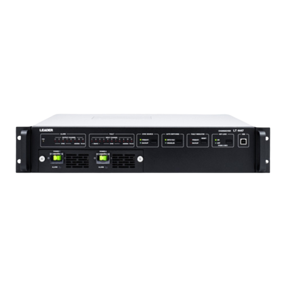
- Page 1 LT 4446 / LT 4447 CHANGEOVER INSTRUCTION MANUAL...
-
Page 2: Table Of Contents
TABLE OF CONTENTS GENERAL SAFETY SUMMARY ..................I 1. INTRODUCTION ......................1 Scope of Warranty ........................1 Trademark Acknowledgments ....................1 Operating Precautions ....................... 2 1.3.1 Power Supply Voltage ......................2 1.3.2 Maximum Allowable Input Voltage ..................2 1.3.3 Mechanical Shock ......................2 1.3.4 Electrostatic Damage ...................... - Page 3 Setting the Fault Detection Level (User-defined) ............. 23 4.5.6 Setting the Operation Mode and Standby Time ..............24 Signal I/O ..........................25 LT 4446/4447 Configuration ....................26 4.7.1 Setting the Key Lock ......................26 4.7.2 Switching the Output Signal ..................... 26 4.7.3...
-
Page 4: General Safety Summary
■ Note about Reading This Manual The contents of this manual contain specialized terminology and may be difficult to understand. If you have any questions about the contents of this manual, please contact your local LEADER agent. ■ Symbols and Terms The following symbols and terms are used in this instruction manual and on the instrument to indicate important warnings and notes. - Page 5 Failing to do so could lead to fire. Turn OFF the power switch, and remove the power cord from the outlet. After making sure that fire has not spread anywhere, contact your local LEADER agent.
- Page 6 Using a power cord that does not meet the standards could lead to fire. If the power cord is damaged, stop using it, and contact your local LEADER agent. Using a damaged power cord could lead to electrical shock or fire.
- Page 7 To ensure stable performance, we recommend that you have the instrument calibrated regularly. Also, if the instrument malfunctions, repairs are necessary. For repairs and calibration, contact your local LEADER agent. ■ Routine Maintenance When you clean the instrument, remove the power plug from the outlet.
-
Page 8: Introduction
1. INTRODUCTION INTRODUCTION Thank you for purchasing this LEADER instrument. To use this instrument safely, read this instruction manual thoroughly, and make sure that you know how to use the instrument properly. If some point about the operation of this instrument is still unclear after you have read this instruction manual, refer to the contact information on the back cover of the manual to contact LEADER, or contact your local LEADER agent. -
Page 9: Operating Precautions
1. INTRODUCTION Operating Precautions 1.3.1 Power Supply Voltage Confirm the voltage of the power source before you connect the power cord to it. The power requirements of this product are indicated on the rear panel. Only use a power source that supplies a voltage within the operating voltage range and has a frequency of 50/60 Hz. -
Page 10: Specifications
GENERATOR) and LT 4110 (SYNC GENERATOR), respectively, at close distance. Features ● I/O Connectors The LT 4446/4447 is equipped with 11 sets of I/O connectors (a single set consists of a primary input connector, a backup input connector, and an output connector). ● Input Switching... - Page 11 ● Combining with an LT 4600 or LT 4110 The depths of the LT 4446 and the LT 4600(MULTIFORMAT VIDEO GENERATOR) are the same. The same holds true for the LT 4447 and the LT 4110(SYNC GENERATOR). This makes it easy to wire and operate the devices when you combine them.
-
Page 12: Specifications
2. SPECIFICATIONS Specifications 2.3.1 Compliant Standards SDI Signal 3G-SDI SMPTE ST 372, SMPTE ST 424, SMPTE ST 425 HD-SDI (including HD dual link) SMPTE ST 274, SMPTE ST 292, SMPTE ST 296 SD-SDI ITU-R BT.601, ITU-R BT.656, SMPTE ST 125, SMPTE ST 259 Sync Signal NTSC Black Burst Signal SMPTE ST 170, SMPTE ST 318,... -
Page 13: Input Signals
2. SPECIFICATIONS Ch4 to 10 Return Loss 30 dB (0 to 10 MHz, internally terminated) Insertion Loss 0.3 dB (0 to 10 MHz) Crosstalk -55 dB (0 to 10 MHz) -45 dB (10 to 30 MHz) 75Ω Input Impedance 75Ω Output Impedance Maximum Input Voltage ±1.5V... -
Page 14: Fault Detection
100 to 1400 mV (p-p value of input signal) Ch11 500 to 3000 mV (high level of input signal) Time from When the LT 4446/4447 Turns On to When Error Detection Starts Approx. 1 min. (60 to 80 s) / approx. 4 min. (240 to 320 s) Depending on the instrument that you are using, there will be deviations in the detection level within the ranges shown. -
Page 15: Alarm Detection
2. SPECIFICATIONS 2.3.7 Alarm Detection Alarm Indications Indicates with LEDs when errors are detected in output signals (channels 4 to 11 only), power supply, or fan unit (LT 4447 only) 2.3.8 Key Lock Lock and Unlock Hold down the KEY LOCK key. Auto Key Lock Automatically locks the keys after 60 seconds of inactivity (no key operations) -
Page 16: General Specifications
Pollution Degree Power Requirements Redundancy Supported Voltage 90 to 250 VAC Frequency 50/60 Hz Power Consumption LT 4446 25W max. LT 4447 50W max. Dimensions LT 4446 426 (W) × 44 (H) × 400 (D) mm (excluding protrusions) LT 4447 426 (W) ×... -
Page 17: Panel Description
Key lock turns on automatically after 1 minute of inactivity (no key operations). USB port. Connect to a PC to assign an IP address to the LT 4446/4447. These are power switches. ○ indicates off, and | indicates on. The switches... -
Page 18: Rear Panel
Ground terminal Connect to an external ground. ETHERNET Ethernet port. You can use this port to monitor the LT 4446/4447 using SNMP. REMOTE Remote control connector. You can use this connector to perform functions such as configuring the LT 4446/4447 and transmitting fault information. -
Page 19: Top Panel
Reference DIP switch cover Remove the four screws to access the DIP switches. You can use the DIP switches to configure the LT 4446/4447. An explanation of the DIP switch settings is printed on the back side of the cover. -
Page 20: How To Use
HOW TO USE Attaching the Cover Inlet Stopper A cover/inlet stopper is included with the LT 4446/4447. Use this device to prevent the power cord from being pulled free of the AC inlet. To attach or remove the cover/inlet stopper, follow the procedure below. -
Page 21: Attaching Rack Supports
Attaching Rack Supports To rack mount the LT 4446/4447, attach the supplied rack supports. Using a Phillips head screwdriver (#2), torque the screws to 63 [cN•m] for the LT 4446 and 147[cN•m] for the LT 4447. Be sure to provide additional support for the body of the instrument. If you only use the rack supports to mount the instrument, the instrument case may deform or fall. -
Page 22: Turning The Power On
With the LT 4446, connect the power cords to AC INPUT 1 and AC INPUT 2. When the power turns on, the POWER 1 and POWER 2 indicators on the front panel light in green. -
Page 23: Turning The Power Off
When you turn off the power, the output signals of channels 1 to 11 are set to PRIMARY. DIP Switch Settings Use the DIP switches on the top panel to configure the LT 4446/4447. To access the DIP switches, first remove the DIP switch cover by unscrewing its four screws. To avoid errors, do not connect the signals until you have completed making all the settings. -
Page 24: Setting Method
4. HOW TO USE The settings are listed below. For details on each item, see the following sections in chapter 4. A simple explanation of the settings is also printed on the back side of the DIP switch cover. Table 4-1 List of settings Setting Name Remark... -
Page 25: Setting The Input Signals
4. HOW TO USE 4.5.2 Setting the Input Signals Set the input signal for each channel. The factory default setting is “no input signal” for all channels. Figure 4-6 Input signal settings... - Page 26 4. HOW TO USE The channels that you can apply signals to differ depending on the type of input signal as shown below. The signal switching method is relay for channels 1 to 3 and electronic switch for channels 4 to 11. If the specified signal is not received, it will be detected as a fault.
-
Page 27: Setting The Fault Detection Speed
4.5.3 Setting the Fault Detection Speed For each channel, select the length of time that must elapse before the LT 4446/4447 automatically switches to the backup signal when a fault is detected in the primary signal. You can select this setting for channels 4 to 11. For channels 1 to 3, it is fixed to 70 ms or less. - Page 28 4. HOW TO USE Table 4-3 Setting the fault detection speed Fault Detection Speed Input DIP Switch Position Number channel OFF (high speed) ON (low speed) Top row 1.5 H or less 60 ms or less 1.5 H or less 60 ms or less 1.5 H or less 60 ms or less...
-
Page 29: Setting The Fault Detection Reference
4. HOW TO USE 4.5.4 Setting the Fault Detection Reference If the fault detection speed is set to low speed or for channels 1 to 3, select the level at which a fault is to be detected for each input signal. Set either VREF-LOW or VREF-HIGH to ON. -
Page 30: Setting The Fault Detection Level (User-Defined)
Below is an example of a procedure to apply signals to channel 1 using user setting 1. Set DIP switches SW1 and SW3 of CH-1 (S2) to ON. Restart the LT 4446/4447 to apply the new settings. Connect between the input signal and PRIMARY an attenuator with an appropriate attenuation (3 to 6 dB) for detecting faults. -
Page 31: Setting The Operation Mode And Standby Time
● Setting the Standby Time You can select the length of time that the LT 4446/4447 waits from the time that it turns ON to the time that it begins operating. Select a setting that is appropriate for the rise time of the system signal source that you are connected to. -
Page 32: Signal I/O
4. HOW TO USE Signal I/O Apply the primary signal to PRIMARY and the backup signal to BACKUP. The input signal impedance is 75 Ω. Terminate the output connectors at 75 Ω. (The signal that is not selected with the front-panel SYNC SOURCE setting is terminated internally at 75 Ω.) Depending on the front-panel SYNC SOURCE setting, the primary or backup signal is transmitted from the OUTPUT connector. -
Page 33: Lt 4446/4447 Configuration
4.7.1 Setting the Key Lock The LT 4446/4447 locks its keys after 1 minute of inactivity (no key operations). When the key lock is on, front-panel key operations are not accepted. To perform front-panel key operations, turn the key lock off. Hold down the KEY LOCK key for 3 seconds to turn the key lock on and off. - Page 34 4. HOW TO USE Depending on the AUTO SWITCHING setting and the MODE DIP switch setting, the operation of the LT 4446/4447 differs as shown below. For details on MODE, see 4.5.6, “Setting the Operation Mode and Standby Time” Reference...
-
Page 35: Lt 4446/4447 Indications
4. HOW TO USE LT 4446/4447 Indications 4.8.1 Fault Indication ● Fault Indication There are two areas for indicating faults: FAULT and FAULT INDICATOR. Both areas indicate the fault detection of input signals. In the FAULT area, the LED of a fault-detected channel lights in red. -
Page 36: Alarm Indications
• When one of the power supplies is not turned on (the LED of the power supply that is off lights) • When the fan in a power supply unit stops (LT 4447 only) Figure 4-19 LT 4446 power supply alarm indications Figure 4-20 LT 4447 power supply alarm indications... - Page 37 ● Fan Alarm Indication (LT 4447 only) The FAN LED lights in red when an error occurs in the fan unit on the rear panel. If the LED lights even when the fan is installed properly, contact your local LEADER agent. Figure 4-21 Fan alarm indication...
-
Page 38: Remote Control
FAULT Transmits a high-level signal when a fault is detected in PRIMARY or INDICATOR BACKUP. Even when the input signal returns to normal, the LT 4446/4447 retains the high-level signal until the error is reset. RESET Apply a low-level signal to reset fault detection. - Page 39 5. REMOTE CONTROL Table 5-2 Remote connector I/O specifications I/O Specifications Connection Example Connect a switch to apply a low-level signal. Connect one side of the switch to the remote connector and the other side to ground. Connect an LED so that it will light when a high-level signal is transmitted.
-
Page 40: Ethernet Control
DHCP client and DNS resolver features are not supported. SNMP Configuration Software Before using SNMP, you must assign an IP address to the LT 4446/4447. To do so, you need to first install the SNMP configuration software (hereafter referred to as the software) in your PC and connect the LT 4446/4447 to your PC. - Page 41 6. ETHERNET CONTROL When the following window appears, select the installation folder, and click Next. Figure 6-2 Installation 2 When the following window appears, click Next. Figure 6-3 Installation 3...
-
Page 42: Uninstallation
6. ETHERNET CONTROL When the following window appears, the installation is complete. Click Close. When the installation is complete, two MIB files LT4446-MIB.txt and LT4447-MIB.txt are created on the desktop. Figure 6-4 Installation 4 6.1.2 Uninstallation To uninstall the software, select “lt4446”in Programs and Features of Control Panel, and click Uninstall. -
Page 43: Connection
The latest USB driver can be downloaded from http://www.ftdichip.com/Drivers/VCP.htm This section describes the procedure to connect the LT 4446/4447 to a PC and configure the LT 4446/4447 network and SNMP settings. Connect the USB port on the LT 4446/4447 front panel to the PC’s USB port. -
Page 44: Window Explanations
Enter the proper values in the Network and SNMP areas, and click SUBMIT. When the following window appears, click OK. Figure 6-7 Configuration complete Restart the LT 4446/4447. The network settings are applied after you restart the LT 4446/4447. 6.1.4 Window Explanations Figure 6-8 Window explanation ●... - Page 45 255.255.255.0 Default Gateway: 0.0.0.0 ● Date/Time Set the date and time on the LT 4446/4447. Enter the values, and then click Set. ● Software Version Pressing GET shows the LT 4446/4447 firmware version. ● SNMP Set the IP address of the TRAP transmission destination. If you set this to 0.0.0.0, TRAPs will not be transmitted.
-
Page 46: Snmp
FROM SNMPv2-CONF; 6.2.3 HOW TO USE To notify the SNMP managers of errors that the LT 4446/4447 generates, follow the procedure below. Configure the LT 4446/4447. From the software installed in your PC, set the IP address, subnet mask, default gateway, and SNMP manager IP. -
Page 47: Enterprise Mib
MIB.txt. 6.1.1, “Installation” Reference ● MIB Structure The LT 4447 MIB structure is shown below. The structure is similar for the LT 4446 (31). lt4447 OBJECT IDENTIFIER ::= { leader 32 } standard OBJECT IDENTIFIER ::= { lt4447 1 }... - Page 48 6. ETHERNET CONTROL ● ACCESS In the tables, “ACCESS” indicates the following: Information that can be read from the SNMP managers R/W: Information that can be read and written from the SNMP managers Table 6-1 fanUnit(1) group (LT 4447 only) SYNTAX ACCESS VALUE...
- Page 49 6. ETHERNET CONTROL Table 6-5 ch4(7) group to ch11(14) group SYNTAX ACCESS VALUE Description ch4InputStatus ch4.1 INTEGER Normal Error-primary Error-backup Error-primary-backup ch4OutputStatus ch4.2 INTEGER Normal Error-output ch5InputStatus ch5.1 INTEGER Same as ch4(7) group ch5OutputStatus ch5.2 INTEGER Same as ch4(7) group ch6InputStatus ch6.1 INTEGER...
- Page 50 6. ETHERNET CONTROL Table 6-7 remote(3) group SYNTAX ACCESS VALUE Description remoteAutoSwitching remote.1 INTEGER remoteToggleSyncSource remote.2 INTEGER remoteFaultReset remote.3 INTEGER Table 6-8 ch1format(1) group to ch3format(3) group SYNTAX ACCESS VALUE Description ch1FormatStatus1 ch1format.1 INTEGER Disable NTSC 720P 1080i/P User define 1 User define 2 SD-SDI HD-SDI/3G-SDI...
- Page 51 6. ETHERNET CONTROL Table 6-9 ch4format(4) group to ch8format(8) group SYNTAX ACCESS VALUE Description ch4FormatStatus1 ch4format.1 INTEGER Disable NTSC 720P 1080i/P User Define 1 User Define 2 ch4FormatStatus2 ch4format.2 INTEGER Disable 60Hz (1080i/720P) 59.94Hz (1080i/720P) 50Hz (1080i/720P) 30Hz (1080P/720P) 29.97Hz (1080P/720P) 25Hz (1080P/720P) 24Hz (1080P/720P) 23.98Hz (1080P/720P)
- Page 52 6. ETHERNET CONTROL Table 6-11 ch11format(11) group SYNTAX ACCESS VALUE Description ch11FormatStatus1 ch11format.1 INTEGER Disable User define 1 User define 2 Word clock ch11FormatStatus2 ch11format.2 INTEGER Disable ch11FormatStatus3 ch11format.3 INTEGER Disable Table 6-12 target(1) group SYNTAX ACCESS VALUE Description managerIp target.1 IP ADDRESS *.*.*.*...
-
Page 53: Specific Trap Type
6. ETHERNET CONTROL 6.2.5 Specific Trap Type Table 6-13 Specific trap type IDs Specific Event Name Description Object Data Trap Type ID fanUnitStatus Fan unit status change detection fanUnit.status powerUnit1Status Power supply unit 1 status change detection powerUnit1.status powerUnit1.fanStatus powerUnit2Status Power supply unit 2 status change detection powerUnit2.status powerUnit2.fanStatus... -
Page 54: Maintenance (Lt 4447 Only)
7. MAINTENANCE (LT 4447 ONLY) MAINTENANCE (LT 4447 ONLY) Cleaning the Air Filters (When they are dirty) The power units on the front panel have air filters. When the air filters become dirty, clean them by following the procedure below. You can clean them while the power is turned on. Turn the sub-panel screws counterclockwise, and remove the sub panel. -
Page 55: Replacing The Air Filters (Once Every Two Years)
Air filters are consumables. If they tear or if two years have passed since the previous replacement, replace them by following the procedure below. You can replace them while the power is turned on. ● Replacement Parts To obtain parts, contact your local LEADER agent. Part No. Name Specifications... -
Page 56: Replacing The Power Supply Unit (Once Every Three Years)
You can replace them while the power is turned on. (The power supply unit that you are replacing must be turned off.) ● Replacement Unit To obtain a replacement unit, contact your local LEADER agent. Part No. Name... - Page 57 7. MAINTENANCE (LT 4447 ONLY) Check that the power switch of the new power supply unit is off (○), and insert the unit. Check that vertical orientation. The label should be on top. When it is inserted properly, the ALARM LED turns on. Tighten the power supply unit screws, and attach the sub panel.
- Page 58 Following information is for Chinese RoHS only 所含有毒有害物质信息 部件号码: LT 4446 / LT 4447 此标志适用于在中国销售的电子信息产品,依据2006年2月28日公布的 《电子信息产品污染控制管理办法》以及SJ/T11364-2006《电子信息产品污染 控制标识要求》,表示该产品在使用完结后可再利用。数字表示的是环境保护使 用期限,只要遵守与本产品有关的安全和使用上的注意事项,从制造日算起在数 字所表示的年限内,产品不会产生环境污染和对人体、财产的影响。 产品适当使用后报废的方法请遵从电子信息产品的回收、再利用相关法令。 详细请咨询各级政府主管部门。 产品中有毒有害物质或元素的名称及含量 部件名称 有毒有害物质或元素 Hazardous Substances in each Part Parts 铅 汞 镉 六价铬 多溴联苯 多溴二苯醚 (Pb) (Hg) (Cd) (Cr(Ⅵ)
- Page 59 LEADER ELECTRONICS CORP. 2-6-33 Tsunashima-Higashi, Kohoku-ku, Yokohama 223-8505, Japan PHONE:81-45-541-2123 FAX:81-45-541-2823 http://www.leader.co.jp May 1, 2014 Ver. 1...
Need help?
Do you have a question about the LT 4446 and is the answer not in the manual?
Questions and answers