
Related Manuals for Leader LV 7770


Summary of Contents for Leader LV 7770
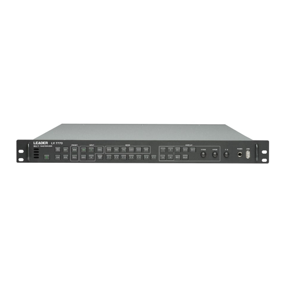
- Page 1 LV 7770 MULTI RASTERIZER LV 7770 OP70 16CH DIGITAL AUDIO ADAPTER LV 5770SER03A TRI SYNC / COMPOSITE LV 5770SER08 SDI INPUT LV 5770SER09(A) SDI INPUT / EYE LV 5770SER42 ANALOG AUDIO INSTRUCTION MANUAL...
-
Page 2: Table Of Contents
Analog Video I/O Connectors (LV 5770SER03A) ............13 2.3.6 External Sync Signal Input Connectors (LV 5770SER03A, LV 5770SER08, and LV 5770SER09A) ..........................13 2.3.7 Audio I/O Connectors (LV 5770SER42 and LV 7770 OP70) .......... 14 2.3.8 Video Output Connectors....................15 2.3.9 Control Connectors ......................15 2.3.10... - Page 3 2.3.24 SDI Signal Status Display (LV 5770SER08 and LV 5770SER09A) ........ 27 2.3.25 Analog Composite Signal Status Display (LV 5770SER03A) ......... 29 2.3.26 Event Log ........................29 2.3.27 SDI Analysis Features (LV 5770SER08 and LV 5770SER09A) ........30 2.3.28 SDI Ancillary Data List Display (LV 5770SER08 and LV 5770SER09A) ......31 2.3.29 Lip Sync Measurement (LV 5770SER08 and LV 5770SER09A) ........
- Page 4 I/O Settings ........................... 68 7.1.1 Configuring SDI Input Settings (LV 5770SER08 and LV 5770SER09A) ......68 7.1.2 Rear Panel Settings ....................... 71 Configuring the LV 7770 ....................... 74 7.2.1 General Settings ......................74 7.2.2 Configuring Ethernet Settings ..................76 7.2.3 Remote Control Settings ....................
- Page 5 Deleting Presets ........................96 Copying All Presets ....................... 97 9.4.1 Copying All Presets from the LV 7770 to a USB Memory Device ........97 9.4.2 Copying All Presets from a USB Memory Device to the LV 7770 ........98 10. REMOTE CONTROL ....................99 11.
-
Page 6: General Safety Summary
■ Note about Reading This Manual The contents of this manual contain specialized terminology and may be difficult to understand. If you have any questions about the contents of this manual, please contact your local LEADER agent. ■ Symbols and Terms The following symbols and terms are used in this instruction manual and on the instrument to indicate important warnings and notes. - Page 7 Failing to do so could lead to fire.Turn off the power switch, and remove the power cord from the outlet. After making sure that fire has not spread anywhere, contact your local LEADER agent.
- Page 8 Using a power cord that does not meet the standards could lead to fire. If the power cord is damaged, stop using it, and contact your local LEADER agent. Using a damaged power cord could lead to electrical shock or fire.
- Page 9 To ensure stable performance, we recommend that you have the instrument calibrated regularly. Also, if the instrument malfunctions, repairs are necessary. For repairs and calibration, contact your local LEADER agent. ■ Routine Maintenance When you clean the instrument, remove the power plug from the outlet.
-
Page 10: Introduction
1. INTRODUCTION INTRODUCTION Thank you for purchasing this LEADER instrument. To use this instrument safely, read this instruction manual thoroughly, and make sure that you know how to use the instrument properly. If some point about the operation of this instrument is still unclear after you have read this instruction manual, refer to the contact information on the back cover of the manual to contact LEADER, or contact your local LEADER agent. -
Page 11: About Standby Mode
1. INTRODUCTION 1.2.2 About Standby Mode Even if you press the power switch to turn off this instrument, the instrument remains in standby mode as long as the power cord is connected to the outlet. In standby mode, some of the internal circuits operate and may generate heat. Unless necessary, keep the power cord disconnected from the outlet. -
Page 12: Backup Battery
To continually use the last-memory feature, we recommend that you replace the backup battery with a new one every five years after you purchase the instrument. You cannot replace the backup battery yourself. Contact your local LEADER agent. About Trademarks and Licenses •... -
Page 13: About Terminology Used In This Manual
1. INTRODUCTION About Terminology Used in this Manual ● Single Input Mode This refers to the mode in which the SIM key is off. Press the A and B keys to switch between measuring the signal that is being applied to SDI INPUT A and the signal that is being applied to SDI INPUT B, respectively. -
Page 14: Specifications
The LV 5770SER08 and LV 5770SER09A cannot be installed in the instrument at the same time. The LV 5770SER42 and LV 7770 OP70 cannot be installed in the instrument at the same time. In addition to the above, a Dolby option can be installed that enables the measurement of Dolby E and Dolby Digital signals. - Page 15 Not only can captured data be displayed by the LV 7770, but it can also be compared with an input signal or saved to a USB memory device. It is easy to view the saved data on a PC.
- Page 16 ● Eye Pattern Display (LV 5770SER09A) When the eye pattern display option is installed in the LV 7770, the LV 7770 can display the eye pattern waveforms and jitter waveforms of 3G-SDI, HD dual link, HD-SDI, and SD-SDI signals. (Channel A or B, whichever is selected, is displayed.) An eye pattern's amplitude, rise time, fall time, DC offset, timing jitter, current jitter, rising edge overshoot, and falling edge overshoot can be measured automatically.
- Page 17 Remote Controller (LV 7770-01; sold separately) Because the remote controller panel is the same as the LV 7770 panel, you can think of it as an extension of the LV 7770 panel when you use it to remotely control the LV 7770.
-
Page 18: Specifications
2. SPECIFICATIONS Specifications 2.3.1 SDI Video Signal Formats and Standards (LV 5770SER08 and LV 5770SER09A) Bit Rate 3G-SDI 2.970 Gbps or 2.970/1.001 Gbps HD-SDI 1.485 Gbps or 1.485/1.001 Gbps SD-SDI 270 Mbps Table 2-1 SD-SDI video signal formats and standards Color System Quantization Scanning... - Page 19 2. SPECIFICATIONS Table 2-4 3G-SDI level A video signal formats and standards Color System Quantization Scanning Frame (Field) Rates Compliant Standard 4:2:2 10 bits 1080p 60/59.94/50 SMPTE ST 424 SMPTE ST 425 12 bits 1080p 30/29.97/25/24/23.98 1080PsF 30/29.97/25/24/23.98 1080i 60/59.94/50 4:4:4 10 bits 1080p...
- Page 20 Format Setting Automatic and manual Automatic 3G-SDI and HD Dual Link The LV 7770 detects the format information within the payload ID (SMPTE ST 352) and automatically sets the format. HD-SDI and SD-SDI The LV 7770 determines the format from the input signal's synchronization information and automatically sets the format.
-
Page 21: Embedded Audio Playback Format (Lv 5770Ser08 And Lv 5770Ser09A)
2. SPECIFICATIONS 2.3.2 Embedded Audio Playback Format (LV 5770SER08 and LV 5770SER09A) Compliant Standards 3G-SDI, HD-SDI, and HD Dual Link SMPTE ST 299 SD-SDI SMPTE ST 272 Format LPCM, Dolby-E (option), Dolby Digital (option) Quantization 24 bits Clock Generation Generated from the video clock Synchronization All audio channels must be synchronized with the video clock. -
Page 22: Analog Video I/O Connectors (Lv 5770Ser03A)
2. SPECIFICATIONS SDI Output Output Connectors Two BNC connectors Output Signal Serial reclocked input SDI signal 3G-SDI, HD-SDI, and SD-SDI 1 output (switchable between channels A and B) 1 output (fixed to channel B) HD Dual Link 1 output (link channel A or B) Output Impedance 75 Ω... -
Page 23: Audio I/O Connectors (Lv 5770Ser42 And Lv 7770 Op70)
Sampling Frequency 48 kHz Output Signal Channels 1 to 8 for SDI embedded audio Channels 9 to 16 for SDI embedded audio (LV 7770 OP70) 8 channels of audio are displayed on the screen. (Dolby signals are decoded and generated.) -
Page 24: Video Output Connectors
Used to save captured data, event logs, preset data, data dumps, and loudness logs. Ethernet Port (*1) Compliant Standard IEEE802.3 Supported Protocol TELNET, FTP, SNMP, HTTP, SNTP I/O Connectors RJ-45 Function Remote control from an external PC or the LV 7770-01 Type 10Base-T, 100Base-TX... -
Page 25: Screen Capture
Input Voltage Range 0 to 5 VDC Control Connector 15-pin D-sub (female) Locking screws Inch screws (No.4-40UNC) You cannot use TELNET and the LV 7770-01 at the same time. 2.3.10 Screen Capture Function Captures the display Display Displays only the captured image or overlays the... -
Page 26: Presets
Preset Loading Method Front panel, remote control connector (*2), or ethernet Copying All preset data can be copied from the LV 7770 to a USB memory device or from a USB memory device to the LV 7770. Settings related to whether the instrument is on or off, the ethernet connector, the remote control connector, the date, and the time are not saved. - Page 27 2. SPECIFICATIONS Display Colors Seven colors to choose from; a different color for each input channel Vertical Axis Gain ×1, ×5 Variable Gain ×0.2 to ×2 Amplitude Accuracy ×1 ±0.5 % ×5 ±0.2 % 3G-SDI, HD Dual Link (1080p/60, 1080p/59.94, 1080p/50) Y Signal ±0.5 % for 1 to 60 MHz Signal...
-
Page 28: Analog Composite Signal Video Waveform Display (Lv 5770Ser03A)
2. SPECIFICATIONS 2.3.15 Analog Composite Signal Video Waveform Display (LV 5770SER03A) Waveform Operations Line Select Selected line display Sweep Mode H, V Display Color Seven colors to choose from Vertical Axis Scale Composite Signal NTSC -40 to 100 IRE -0.3 to 0.7 V HD Tri-level Sync Signal -0.3 to 0.7 V, -43 to 100 % (the unit is switchable between V and %) -
Page 29: Sdi Signal Vector Waveform Display (Lv 5770Ser08 And Lv 5770Ser09A)
2. SPECIFICATIONS 2.3.16 SDI Signal Vector Waveform Display (LV 5770SER08 and LV 5770SER09A) Simul Mode Display Format Mixed, tiled Display Colors Seven colors to choose from; a different color for each input channel Blanking Interval(*1) Masked Pseudo-Composite Display Artificially converts component signals into composite signals and displays the result Line Select Selected line display... -
Page 30: Sdi Signal 5-Bar Display (Lv 5770Ser08 And Lv 5770Ser09A)
2. SPECIFICATIONS 2.3.18 SDI Signal 5-Bar Display (LV 5770SER08 and LV 5770SER09A) Simul Mode Display Format Tiled only Function Converts an SDI signal into Y, R, G, B, and composite values and then displays the five peak levels Channel Assignment RGB, GBR Scale mV, %... - Page 31 2. SPECIFICATIONS Percentage Display Displays luminance or RGB components as percentages Level Display Displays RGB components with 256 levels (8 bits) Measured points Measurement sizes 1 pixel, 3 × 3 pixels, or 9 × 9 pixels CINELITE Advanced Display Features Synchronized marker display, vector marker display Synchronized Marker Display Synchronizes the markers on the vector display or waveform display to the measurement points of the...
-
Page 32: Analog Composite Signal Picture Display (Lv 5770Ser03A)
2. SPECIFICATIONS 2.3.20 Analog Composite Signal Picture Display (LV 5770SER03A) Quantization 8 bits Display Sizes Fit, full frame, real, ×2 Frame Rate The frame rate is converted and displayed using the internal sync signal Aspect Marker Display 16:9, 14:9, 13:9 Aspect Marker Format Line, shadow (99 levels), black Safety Marker Size... -
Page 33: Digital Audio Display
Any two groups from groups 1, 2, 3, and 4, all groups 1, 2, 3, and 4 Digital Audio Group A, group B (LV 7770 OP 70), group A + group B (set to the input connectors) Display Type Level meter, Lissajous and correlation meter, surround,... - Page 34 1 to 5000 ms Parity Error Counts the number of times that the input signal's parity bit and the parity bit recalculated by the LV 7770 differ Validity Error Counts the number of times that the input signal's validity bit is 1...
- Page 35 2. SPECIFICATIONS Loudness Display Function Loudness chart display, numeric display, log, level meter display, peak value display Compliant Standard ITU-R BS.1770, ARIB TR-B32, EBU R128, ATSC A/85 Measurement Channel Simultaneous measurement of two audio sources Mode (Main) Monaural, stereo, 5.1, user specified channel Mode (Sub) Off, monaural, stereo Channel Selection...
-
Page 36: Analog Audio Display (Lv 5770Ser42)
2. SPECIFICATIONS 2.3.23 Analog Audio Display (LV 5770SER42) Input Signal Analog audio input Displayed Channels Up to 8 channels Display Type Level meter, Lissajous, surround, status, loudness Level Meter Display The specifications other than those listed here are the same as the digital audio specifications Scale Reference Level Scales 4 dBu to -20 dBFS Level Accuracy... - Page 37 2. SPECIFICATIONS Detects errors when the phase difference between links A and B is 100 clocks or more Cable Length Measurement Error (LV 5770SER09A) Displays an error if the specified cable length is exceeded 3G-SDI 10 to 105 m, 5 m steps HD-SDI 5 to 130 m, 5 m steps SD-SDI...
-
Page 38: Analog Composite Signal Status Display (Lv 5770Ser03A)
1 frame Horizontal ±1 line 2.3.26 Event Log Function Records detected errors, events—such as the LV 7770 switching between input signals, and time stamps. Recording Capacity Up to 1000 events Operation Records all events from start to finish Data Output... -
Page 39: Sdi Analysis Features (Lv 5770Ser08 And Lv 5770Ser09A)
2. SPECIFICATIONS 2.3.27 SDI Analysis Features (LV 5770SER08 and LV 5770SER09A) Data Dump Display HD-SDI and SD-SDI Display Format Displays data separated by serial data sequence or by channel 3G-SDI Display Format Stream 1, stream 2, stream A and B simultaneously HD Dual Link Display Format Link A, link B, link A and B simultaneously Line Select... -
Page 40: Sdi Ancillary Data List Display (Lv 5770Ser08 And Lv 5770Ser09A)
Reference Signal A Leader TSG that supports lip syncing Measurement Method Measures the time difference when the luminance level of the video signal exceeds the specified value and when... -
Page 41: Sdi Closed Caption Packet Display (Lv 5770Ser08 And Lv 5770Ser09A)
2. SPECIFICATIONS Measurement Range (Bar Display) ±50 ms, ±100 ms, ±500 ms, ±1.0 s, ±2.5 s Measurement Range (Numeric Display) ±3999 ms Measurement Resolution 1 ms Thumbnail Display Picture, audio level meter 2.3.30 SDI Closed Caption Packet Display (LV 5770SER08 and LV 5770SER09A) Table 2-7 SD-SDI video signal formats and standards Feature Compliant Standard... -
Page 42: Eye Pattern Display (Lv 5770Ser09A)
2. SPECIFICATIONS 2.3.31 Eye Pattern Display (LV 5770SER09A) Display Displays the input SDI waveform before equalizing 3G-SDI, HD-SDI, SD-SDI Displays channel A or B, whichever is selected HD Dual Link Displays link A or B, whichever is selected Method Equivalent time sampling Frequency Response 7 GHZ -3dB (converted from the rise time) Amplitude Accuracy... -
Page 43: Jitter Display (Lv 5770Ser09A)
2. SPECIFICATIONS 2.3.32 Jitter Display (LV 5770SER09A) Display Displays the jitter component of an SDI signal 3G-SDI, HD-SDI, SD-SDI Displays channel A or B, whichever is selected HD Dual Link Displays link A or B, whichever is selected Method Phase detection method Gain ×8, ×2, ×1 Measurement Range... -
Page 44: Eye Pattern And Jitter Detection (Lv 5770Ser09A)
2. SPECIFICATIONS 2.3.33 Eye Pattern and Jitter Detection (LV 5770SER09A) Error Detection On or off per item Error Threshold Settings Can be set individually for 3G-SDI, HD-SDI, and SD-SDI signals Event Log Stores eye patterns and jitter errors Threshold Values 100 % of the values in the SMPTE standard Eye-Pattern Amplitude Upper Limit... -
Page 45: Alarm Output Feature
2. SPECIFICATIONS 2.3.35 Alarm Output Feature Display Indication When an error occurs or the fan stops rotating, an alarm is displayed. Remote Control Connector Output Each time that an error occurs or the fan stops rotating, a signal is transmitted from the remote control connector to indicate this occurrence. -
Page 46: Panel Description
3. PANEL DESCRIPTION PANEL DESCRIPTION Front Panel Figure 3-1 Front panel Table 3-1 Front panel description Name Description Power switch Press this switch to turn the instrument on. Hold this switch down to turn the instrument off. See section 4.3, “Turning the Instrument On and Off.” Switches the SDI signal sync signal. - Page 47 This is a standard-plug headphone jack. When a pair of headphones are connected to this jack, the LV 7770 transmits the audio that is embedded in an SDI signal or the audio that is applied to the DIGITAL AUDIO IN/OUT.
-
Page 48: Rear Panel
AUDIO See section 4.5.6, “Digital Audio Signal I/O.” (GROUP A) IN/OUT DIGITAL These are LV 7770 OP70 I/O connectors. AUDIO These are used to receive and transmit digital audio signals. (GROUP B) See section 4.5.6, “Digital Audio Signal I/O.” IN/OUT REMOTE This is a D-sub, 15-pin remote control connector. - Page 49 3. PANEL DESCRIPTION Name Description from channel A. See section 4.5.2, “SDI Signal Output (LV 5770SER08 and LV 5770SER09A).” SDI OUTPUT B This generates the reclocked signal of the SDI signal received through the SDI INPUT B connector. See section 4.5.2, “SDI Signal Output (LV 5770SER08 and LV 5770SER09A).” Ground This is used to connect the instrument to an external ground.
-
Page 50: Before You Begin Measuring
4. BEFORE YOU BEGIN MEASURING BEFORE YOU BEGIN MEASURING Cover/Inlet Stopper A cover/inlet stopper is included with the instrument. Use this device to prevent the power cord from being pulled free of the AC inlet. 4.1.1 Attaching the Cover/Inlet Stopper Cover the power cord with the cover/inlet stopper. -
Page 51: Connecting To A Display
To turn on the power, press the power switch. The power switch LED lights, and the instrument turns on. When you turn on the power, the LV 7770 starts with the same panel settings that were being used when it was last turned off. -
Page 52: Signal I/O
See section 5.4, “Selecting the Input Channel.” • Cables It has been confirmed for each channel that errors do not occur when the LV 7770 receives an 800 mVp-p stress pattern through the following cables. LS-5CFB cable, 70 m LS-5CFB cable, 110 m L-5C2V cable, 260 m •... -
Page 53: Sdi Signal Output (Lv 5770Ser08 And Lv 5770Ser09A)
SDI INPUT A or SDI INPUT B. Use a commercially available HDMI cable to connect the LV 7770 to an LCD monitor. Press A or B to select the output channel. For HD dual link signals, a signal consisting of the combination of links A and B is generated. -
Page 54: External Sync Signal Input (Lv 5770Ser03A, Lv 5770Ser08, And Lv 5770Ser09A)
(phase difference display). (*1) Apply an external sync signal to an external sync signal input connector, and then press EXT. The LV 7770 determines the sync signal format automatically. As shown in the figure below, the external sync signal input connectors are loop-through. - Page 55 4. BEFORE YOU BEGIN MEASURING External sync signals that are compatible with each input signal are indicated with a check mark in the following table. Table 4-2 External sync signal formats (SD, HD, and HD dual link) Input Signal Format HD dual link NTSC with 10 field ...
- Page 56 4. BEFORE YOU BEGIN MEASURING Table 4-3 External sync signal formats (3G) Input Signal Format 3G-A 3G-B 3G-B (2map) NTSC with 10 field ID (59.94 Hz)(*1) NTSC (59.94 Hz) ...
-
Page 57: Composite Signal I/O (Lv 5770Ser03A)
4. BEFORE YOU BEGIN MEASURING 4.5.5 Composite Signal I/O (LV 5770SER03A) Figure 4-11 Composite I/O connectors • Signal Input Apply an NTSC/PAL composite signal or an HD tri-level sync signal to INPUT A or INPUT B. To switch the measurement channel, press A or B. Note that pressing the SIM key has no effect. -
Page 58: Analog Audio Signal I/O (Lv 5770Ser42)
4. BEFORE YOU BEGIN MEASURING 4.5.7 Analog Audio Signal I/O (LV 5770SER42) Figure 4-13 Analog audio I/O connector (female, inch screws) Table 4-4 Analog audio I/O connector pinout example Pin No. Name Pin No. Name Function INPUT1+ INPUT1- Analog audio input 1 INPUT2+ INPUT2- Analog audio input 2... - Page 59 100 kΩ. • About the Unit LV 7770 audio signals are displayed in units of dBFS with 4 dBu scaled to -20 dBFS. A conversion table between dBu and dBFS is shown below. Table 4-5 dBu, dBFS conversion table...
-
Page 60: General Display Explanation
4. BEFORE YOU BEGIN MEASURING General Display Explanation Figure 4-14 General display explanation Table 4-6 General display explanation Name Description Date and time The date and time are displayed here. See sections 7.2.1, “General Settings” and 7.2.4, “Setting the Date and Time.”... -
Page 61: Panel Operation Basics
Alarm indication This displays various alarms. If either of the following alarms is displayed, contact your local LEADER agent. FAN ALARM: This appears when there is a problem with the fan. OVER HEAT: This appears when the internal temperature has risen to an abnormal level. -
Page 62: Function Menu Operations
4. BEFORE YOU BEGIN MEASURING 4.7.2 Function Menu Operations This section explains how to operate the function menu, using the function menu on the vector display as an example. The function menu items correspond to F•1 to F•7. Figure 4-15 Function menu operations •... -
Page 63: Enabling And Releasing The Key Lock
Enabling and Releasing the Key Lock You can prevent accidental operations on the LV 7770 by enabling the key lock. The key lock disables all LV 7770 keys except for the power switch. (Remote control is still valid even if the key lock is enabled.) -
Page 64: Operating The Shortcut Key
See section 7.4, “Setting the Shortcut Key.” • DIRECT The panel settings that are registered to the SHORTCUT key are loaded. To register the panel settings, configure the LV 7770 to the settings that you want to register, press MEM, and then press SHORTCUT. • VOLUME You can adjust the headphone volume by pressing SHORTCUT and then turning the function dial (F•D). -
Page 65: Basic Operating Procedures
BASIC OPERATING PROCEDURES This chapter explains the basic operating procedures of the LV 7770. We recommend that you follow these basic operations until you fully understand how the LV 7770 is designed to operate. Figure 5-1 Operating procedures Select the display format. -
Page 66: Selecting The Display Format
5. BASIC OPERATING PROCEDURES Selecting the Display Format The LV 7770 supports both a multi-screen display and a 1-screen display. Press MULTI to switch between the 1-screen display and the multi-screen display. The key's LED lights when the multi-screen display is active. -
Page 67: Selecting The Display Area
5. BASIC OPERATING PROCEDURES Selecting the Display Area The LV 7770 is composed of four screens. Press a key from 1 to 4 to select the area that you want to operate. When the menu is being displayed on the multi-screen display, the selected area is displayed with a blue border. -
Page 68: Selecting The Input Channel
Figure 5-6 Single input mode and simul mode Selecting the Display Mode The LV 7770 has six display modes: WFM (video signal waveform display), VEC (vector display), PIC (picture display), AUDIO (audio display), STATUS (status display), and EYE (eye pattern display). Press MODE on the front panel to select the display mode. - Page 69 5. BASIC OPERATING PROCEDURES WFM(*1) VEC(VECTOR)(*1) VEC(5BAR)(*1) AUDIO STATUS Figure 5-7 Selecting the display mode...
-
Page 70: Detailed Measurement Examples
DETAILED MEASUREMENT EXAMPLES This chapter explains detailed measurement examples. For the basic operating procedures, see chapter 5, “BASIC OPERATING PROCEDURES.” Initialize the LV 7770 immediately before you perform the operating procedures shown here. See section 7.7, “Initializing Settings.” SDI Signal Measurement •... -
Page 71: Sdi Signal Eye Pattern Measurement
Apply an SDI signal to SDI INPUT A or SDI INPUT B on the rear panel. Turn the MULTI key off (optional). The LV 7770 switches to the 1-screen display, which is easier to view. (On the multi-screen display, one of these displays is shown.) This is not supported in simul mode or on the multi-screen display of 3G-B(2map) signals. -
Page 72: Embedded Audio Signal Measurement
Apply an SDI signal to SDI INPUT A or SDI INPUT B on the rear panel. Turn the MULTI key off (optional). The LV 7770 switches to the 1-screen display, which is easier to view. Press AUDIO. Press F•1 SOURCE SELECT and then F•2 1ST GRP SELECT or F•3 2ND GRP SELECT to select the measurement group. -
Page 73: External Digital Audio Signal Measurement
Apply digital audio signals to the DIGITAL AUDIO IN/OUT connectors on the rear panel. Check that the Audio BNC settings are set to INPUT on the REAR PANEL SETUP tab in the system settings. These settings are set to INPUT when the LV 7770 is initialized. See section 7.1.2, “Rear Panel Settings.”... -
Page 74: Analog Audio Signal Measurement
Check that the ANALOG AUDIO setting is set to INPUT on the REAR PANEL SETUP tab in the system settings. This setting is set to INPUT when the LV 7770 is initialized. See sections 4.5.7, “Analog Audio Signal I/O (LV 5770SER42)” and 7.1.2, “Rear Panel Settings.”... -
Page 75: Embedded Audio Signal Output
6. DETAILED MEASUREMENT EXAMPLES Embedded Audio Signal Output You can generate channels 1 to 16 of an audio signal that is embedded in an SDI signal from the rear panel DIGITAL AUDIO IN/OUT connectors. You can generate 8 channels from group A, and 8 channels from group B (OP70). -
Page 76: Analog Audio Signal Output
6. DETAILED MEASUREMENT EXAMPLES Analog Audio Signal Output You can perform a D/A conversion on and generate up to eight channels of embedded audio signals or external digital audio signals as analog audio signals from the rear panel ANALOG AUDIO connector. This section will show the procedure for generating embedded audio signals. -
Page 77: System Settings
7. SYSTEM SETTINGS SYSTEM SETTINGS You can use the system menu to configure LV 7770 settings and optional unit settings. To display the system menu, press SYS. SYS → Figure 7-1 System menu I/O Settings To configure the I/O settings, press F•1 FORMAT IN OUT on the system menu. FORMAT IN OUT is a tab menu. - Page 78 “ILLEGAL FORMAT” will be displayed. Specify a correct format. It may take the LV 7770 approximately 10 seconds to switch to a different format. Table 7-1 Input format settings Link Format...
- Page 79 7. SYSTEM SETTINGS Link Format Color System Pixel Depth Scanning Active Sample Frame Rate (*1) 3G-A YCbCr(4:2:2) 10bit 1080P 1920 60/59.94/50 12bit 1080P 1920 30/29.97/25/24/23.98 1080i 1920 30/29.97/25 1080PsF 1920 30/29.97/25/24/23.98 YCbCr(4:4:4) 10bit 1080P 1920 30/29.97/25/24/23.98 1080i 1920 30/29.97/25 1080PsF 1920 30/29.97/25/24/23.98 720P...
-
Page 80: Rear Panel Settings
7. SYSTEM SETTINGS Link Format Color System Pixel Depth Scanning Active Sample Frame Rate (*1) 3G-B(2map) YCbCr(4:2:2) 10bit 1080P 1920 30/29.97/25/24/23.98 1080i 1920 30/29.97/25 1080PsF 1920 30/29.97/25/24/23.98 720P 1920 60/59.94/50/ 30/29.97/25/24/23.98 Note that when i/PsF Select is set to Interlace, the frame rate is displayed. For example, if the field rate is 59.94 Hz, set the frame rate to 29.97. - Page 81 7. SYSTEM SETTINGS ● GROUP A OUT SEL and GROUP B OUT SEL (OP70) When GROUP A or GROUP B is set to OUTPUT, select the corresponding output signal. The LV 5770SER08 or LV 5770SER09A is required to generate embedded audio signals.
- Page 82 You can also configure this setting by following the procedure in section 7.6, “Selecting the Aspect Ratio.” 4:3: The LV 7770 produces a signal for a 4:3 display. 16:9: For vectors, pictures, and audio waveforms, the LV 7770 generates a signal for a 16:9 display.
-
Page 83: Configuring The Lv 7770
7. SYSTEM SETTINGS Configuring the LV 7770 To configure the LV 7770, press F•2 SYSTEM SETUP on the system menu. SYSTEM SETUP is a tab menu. For details on how to operate tab menus, see section 4.7.3, “Tab Menu Operations.”... - Page 84 7. SYSTEM SETTINGS ● Format (LV 5770SER03A, LV 5770SER08, and LV 5770SER09A) Turn the format indication (for example, 1080i/59.94 or NTSC) that is shown at the top of the screen on or off. ON / OFF ● Date Select the display format for the date that is shown in the upper left of the screen. y = the year in the Gregorian calendar, m = the month, d = the day OFF / y/m/d / m/d/y / d/m/y ●...
-
Page 85: Configuring Ethernet Settings
Configuring Ethernet Settings Configure the Ethernet settings on the ETHERNET SETUP tab. The settings that you specify here will not be initialized even if you initialize the LV 7770. In addition, they are not registered to presets. See chapter 11, “ETHERNET REMOTE CONTROL.”... - Page 86 7. SYSTEM SETTINGS ● TELNET Server Select Select whether to enable the TELNET server feature and the LV 7770-01 (REMOTE CONTROLLER). You cannot use TELNET and the LV 7770-01 at the same time. OFF / ON / LV7770-01 ● FTP Server Select Select whether to enable the FTP server feature.
-
Page 87: Remote Control Settings
Remote Control Settings Use the REMOTE SETUP tab to configure remote control settings. The settings that you specify here will not be initialized even if you initialize the LV 7770. In addition, they are not registered to presets. See chapter 10, “REMOTE CONTROL.”... -
Page 88: Setting The Date And Time
ON. To set the date and time manually, set SNTP Client Select to OFF, and then press F•1 COMPLETE. Then, press F•2 SYSTEM SETUP again. The settings that you specify here will not be initialized even if you initialize the LV 7770. In addition, they are not registered to presets. -
Page 89: Displaying System Information
Displaying System Information To display the system information, press F•3 SYSTEM INFO on the system menu. You can use this screen to view the LV 7770 firmware version and the types of installed optional units. SYS → F•3 SYSTEM INFO →... -
Page 90: Configuring License Settings
4:3: The LV 7770 produces a signal for a 4:3 display. 16:9: For vectors, pictures, and audio waveforms, the LV 7770 generates a signal for a 16:9 display. 16:10: For vectors, pictures, and audio waveforms, the LV 7770 generates a signal for a... -
Page 91: Initializing Settings
7. SYSTEM SETTINGS Initializing Settings To initialize the settings, press F•7 INITIALIZE on the system menu. To proceed with the initialization, press F•1 INIT YES. To cancel the initialization, press F•3 INIT NO. SYS → F•7 INITIALIZE → Figure 7-10 INITIALIZE menu When you initialize the settings, all the settings—excluding those listed below—are initialized. -
Page 92: Capture Feature
You can use the screen capture feature to capture still-image data of the screen. You can save the captured data to USB memory or overlay it on the input signal on the LV 7770 display. ● Frame Capture (LV 5770SER08 and LV 5770SER09A) You can use the frame capture feature to capture single frames of data from the SDI signal. -
Page 93: Screen Capture
Configure the LV 7770 so that the display that you want to capture appears on the screen. Press CAP. When you press CAP, the LV 7770 stores a screen capture of the display in its internal memory. You can also take screen captures by pressing F•2 REFRESH while the capture menu is displayed. -
Page 94: Saving To A Usb Memory Device
If you press CAP and perform an operation such as changing the display mode, the acquired screen capture data is deleted. However, by saving the screen capture data to a USB memory device in BSG format, you can display the screen capture data on the LV 7770 even after you restart the instrument. -
Page 95: Displaying Screen Capture Data Saved To A Usb Memory Device
USB memory as .bsg files, follow the procedure below. (Screen capture data that has been saved in BMP format and screen capture data that has been saved in BSG format on a different model cannot be displayed on the LV 7770.) Press CAP. -
Page 96: Deleting Screen Capture Data Saved To A Usb Memory Device
8. CAPTURE FEATURE 8.1.5 Deleting Screen Capture Data Saved to a USB Memory Device To delete screen capture data that has been saved to a USB memory device, follow the procedure below. (You can also use a PC to delete the data.) Press CAP. -
Page 97: Frame Capture (Lv 5770Ser08 And Lv 5770Ser09A)
Press F•1 TRIGGER to select MANUAL. Press F•2 REFRESH. One frame of data is captured in the LV 7770. (In simul mode, the data of both channels A and B is captured.) The captured frame data is cleared when you change the input channel or other... - Page 98 When the message below appears, press any key except for the power key. If an error occurs during error standby, the LV 7770 captures the frame data at that point and stops the frame capture. (In simul mode, if an error occurs on channel A or channel B, the LV 7770 captures the frame data of the channel in which the error occurred and stops the frame capture.)
-
Page 99: Displaying Frame Capture Data
Saving to a USB Memory Device The frame data captured in the LV 7770 is cleared when the power is turned off. If you want to display it later even after the power is turned off, save the data to USB memory by following the procedure below (save the data in FRM format). - Page 100 F•4 FILE TYPE are set to OFF, or when there is no frame data captured in the LV 7770. When the input signal is 1080i/59.94 and all the file types that you can select with F•4 FILE TYPE are set to ON, it takes about 50 seconds to save the data.
-
Page 101: Displaying Frame Capture Data Saved To A Usb Memory Device
Turn the function dial (F•D) to select the .frm file that you want to display. Press F•1 RECALL. To display frame data, the LV 7770 must be receiving a signal whose format is the same as that of the saved data. The FORMAT item at the bottom of the display shows the format of the saved data. -
Page 102: Deleting Frame Capture Data Saved To A Usb Memory Device
8. CAPTURE FEATURE 8.2.5 Deleting Frame Capture Data Saved to a USB Memory Device To delete frame capture data that has been saved to a USB memory device, follow the procedure below. (You can also use a PC to delete the data.) Press F•6 RECALL on the capture menu. -
Page 103: Preset Feature
• Date and time settings (DATE&TIME) Registering Presets To register a preset, follow the procedure below. Set the LV 7770 to the settings that you want to register. Press MEM. The preset registration display appears. Figure 9-1 Preset registration display... - Page 104 9. PRESET FEATURE Press F•1 COMMENT INPUT. The comment input display appears. You can also copy a comment from a preset that already has a comment saved to it. To copy a comment, on the preset registration display, move the cursor to the preset that has the comment that you want to copy, and press the function dial (F•D).
-
Page 105: Loading Presets
9. PRESET FEATURE Loading Presets To load a preset, follow the procedure below. Press RCLL. The preset load menu appears. Figure 9-4 Preset load menu Press a key from F•1 NO.1 to F•6 NO.6. If the preset that you want to load is number 7 or greater, press F•7 more or turn the function dial (F•D). -
Page 106: Copying All Presets
Copying All Presets 9.4.1 Copying All Presets from the LV 7770 to a USB Memory Device To copy all the presets from the LV 7770 to a USB memory device, follow the procedure below. Press MEM. The preset registration display appears. -
Page 107: Copying All Presets From A Usb Memory Device To The Lv 7770
PRESET_00.PRE (to PRESET_59.PRE) ..Preset number 1 to number 60 9.4.2 Copying All Presets from a USB Memory Device to the LV 7770 To copy all the presets from a USB memory device to the LV 7770, follow the procedure below. Press MEM. -
Page 108: 10. Remote Control
10. REMOTE CONTROL 10. REMOTE CONTROL You can use the remote control connector on the rear panel to load presets, transmit alarm signals, and perform other operations. Use the supplied 15-pin D-sub connector to control the LV 7770. ● Pinout Example This section contains a diagram of the remote control connector, displayed as it appears on the rear panel, and a table that describes the connector's pinout. - Page 109 10. REMOTE CONTROL ● Configuring the LV 7770 To set the remote control connector, use the system settings. For details, see section 7.2.3, “Remote Control Settings.” SYS → F•2 SYSTEM SETUP → F•3 NEXT TAB → F•3 NEXT TAB →...
- Page 110 10. REMOTE CONTROL After a setting is made, it may take about 3 seconds for the operation to finish. If you configure subsequent settings before the initial operation finishes, only the last setting will take effect. All settings in between will be discarded. (In the following example, remote control 2 will be discarded.) Figure 10-4 Remote control timing 2 ●...
- Page 111 10. REMOTE CONTROL The control table when Remote Mode is set to BINARY is shown below. Table 10-3 Loading presets (BINARY) Preset...
- Page 112 10. REMOTE CONTROL Preset ● Controlling the Loudness Measurement The control table when Remote Select is set to Recall and Loudness is shown below. Table 10-4 Controlling the loudness measurement 9p (/P8) 8p (/P7) Clear the loudness measurement Start the loudness measurement Stop the loudness measurement...
-
Page 113: 11. Ethernet Remote Control
LEADER does not guarantee that this feature will work in any network environment. 11.1 TELNET From a PC connected to the same network as the LV 7770, most of the operations that you can perform from the front panel can be controlled remotely. 11.1.1 Procedure Configure the Ethernet settings on the LV 7770's ETHERNET SETUP tab. -
Page 114: How To Enter Commands
Examples of how to enter commands are shown below. With the factory default settings, return values are returned only for queries. If you want the LV 7770 to output return values for all commands, send a "REMOTE:REPLY" with the parameter set to ON. -
Page 115: Telnet Commands
11.1.3 TELNET Commands TELNET commands follow the LV 7770 or the unit menu structure. For explanations of each item, see the LV 7770 or the unit instruction manual. Depending on the current settings, some of the items that are described in this manual may be invalid. - Page 116 11. ETHERNET REMOTE CONTROL Command Parameter SYS:REAR:PIC_MONI_OUT:PIXEL_DEPTH AUTO / 8BIT / 10BIT / 12BIT / ? SYS:REAR:PIC_MONI_OUT:2MAPPING STREAM1 / STREAM2 / ? SYS:GENERAL:MULTI_DISPLAY 2MULTI / 4MULTI / ? SYS:GENERAL:CAPTURE_MODE SCREEN / VIDEO_FRAME / ? SYS:GENERAL:MEM_STR_MODE LOUD2H / LOUD32H / ? SYS:GENERAL:INFO:FORMAT ON / OFF / ? SYS:GENERAL:INFO:DATE...
- Page 117 11. ETHERNET REMOTE CONTROL Command Parameter SYS:INFO:BOARD:COMPOSITE_VIDEO ? (Return value: 0 (not installed) / 1 (installed)) SYS:INFO:BOARD:AUDIO_ANALOG ? (Return value: 0 (not installed) / 1 (installed)) SYS:INFO:BOARD:AUDIO_OP70 ? (Return value: 0 (not installed) / 1 (installed)) SYS:SHORTCUT DIRECT / VOLUME / CAP&WRIT / INTEN / MENU_OFF SYS:INIT None SYS:KEYLOCK...
- Page 118 11. ETHERNET REMOTE CONTROL Command Parameter WFM:SWEEP:H_MAG X1 / X10 / X20 / ACTIVE / BLANK / ? WFM:SWEEP:V_MAG X1 / X20 / X40 / ? WFM:SWEEP:FIELD FIELD1 / FIELD2 / ? WFM:BLANKING:NORMAL REMOVE / H_VIEW / V_VIEW / ALL_VIEW / ? WFM:BLANKING:COMPOSITE REMOVE / V_VIEW / ? WFM:LINE_SELECT...
- Page 119 11. ETHERNET REMOTE CONTROL Command Parameter VECTOR:MODE VECTOR / 5BAR / ? VECTOR:5BAR:SCALE P / MV / ? VECTOR:5BAR:SEQUENCE GBR / RGB / ? VECTOR:5BAR:Y:DATA ? (Return value: maximum Y value, minimum Y value) * For 3G-B (2map), use the "INPUT:STREAM" command to select the stream.
- Page 120 11. ETHERNET REMOTE CONTROL Command Parameter PICTURE:GAIN:CHROMA 0.0 to 200.0 / ? PICTURE:BIAS:R -50.0 to 50.0 / ? PICTURE:BIAS:G -50.0 to 50.0 / ? PICTURE:BIAS:B -50.0 to 50.0 / ? PICTURE:MARKER:FRAME ON / OFF / ? PICTURE:MARKER:CENTER ON / OFF / ? PICTURE:MARKER:ASPECT OFF / 14_9 / 13_9 / 16_9 / 4_3 / 2.39_1 / AFD / ? PICTURE:MARKER:ASPECT:SHADOW...
- Page 121 11. ETHERNET REMOTE CONTROL Command Parameter PICTURE:DISPLAY:THUMBNAIL:HISTO:G ON / OFF / ? PICTURE:DISPLAY:THUMBNAIL:HISTO:B ON / OFF / ? PICTURE:DISPLAY:SD 4_3 / 16_9 / ? PICTURE:S_IMPOSE:SMPTE ON / OFF / ? PICTURE:S_IMPOSE:FORMAT FMT_608_708 / FMT_608_608 / FMT_VBI / FMT_708 / ? PICTURE:S_IMPOSE:LANGUAGE_608 CC1 / CC2 / CC3 / CC4 / TEXT1 / TEXT2 / TEXT3 / TEXT4 / ?
- Page 122 11. ETHERNET REMOTE CONTROL Command Parameter STATUS:AV_PHASE:CH2:DATA ? (Return value: data / MISSING / UNLOCK / NO_SIGNAL / -) STATUS:AV_PHASE:CH3:DATA ? (Return value: data / MISSING / UNLOCK / NO_SIGNAL / -) STATUS:AV_PHASE:CH4:DATA ? (Return value: data / MISSING / UNLOCK / NO_SIGNAL / -) STATUS:AV_PHASE:CH5:DATA ? (Return value: data / MISSING / UNLOCK /...
- Page 123 11. ETHERNET REMOTE CONTROL Command Parameter STATUS:ANC_PACKET:JPN_CC3:DATA ? (Return value: DETECT / MISSING / -) STATUS:ANC_PACKET:NET_Q:DATA ? (Return value: DETECT / MISSING / -) STATUS:ANC_PACKET:TRIGGER:DATA ? (Return value: DETECT / MISSING / -) STATUS:ANC_PACKET:USER1:DATA ? (Return value: DETECT / MISSING / -) STATUS:ANC_PACKET:USER2:DATA ? (Return value: DETECT / MISSING / -) STATUS:ANC:PKT:PAYLOAD_ID...
- Page 124 11. ETHERNET REMOTE CONTROL Command Parameter STATUS:ANC:PKT:ARIB:NETQ:BIT:Q30 ON / OFF / ? STATUS:ANC:PKT:ARIB:NETQ:BIT:Q31 ON / OFF / ? STATUS:ANC:PKT:ARIB:NETQ:BIT:Q32 ON / OFF / ? STATUS:ANC:PKT:ARIB:NETQ:BIT:S1 ON / OFF / ? STATUS:ANC:PKT:ARIB:NETQ:BIT:S2 ON / OFF / ? STATUS:ANC:PKT:ARIB:NETQ:BIT:S3 ON / OFF / ? STATUS:ANC:PKT:ARIB:NETQ:BIT:S4 ON / OFF / ? STATUS:ANC:PKT:ARIB:NETQ:BIT:S5...
- Page 125 11. ETHERNET REMOTE CONTROL Command Parameter STATUS:ERROR:GAMUT:LPF HD1M_SD1M / HD2.8M_SD1M / OFF / ? STATUS:ERROR:GAMUT ON / OFF / ? STATUS:ERROR:GAMUT:UPPER 90.8 to 109.4 / ? STATUS:ERROR:GAMUT:LOWER -7.2 to 6.1 / ? STATUS:ERROR:GAMUT:AREA 0.0 to 5.0 / ? STATUS:ERROR:GAMUT:DURATION 1 to 60 / ? STATUS:ERROR:C_GAMUT ON / OFF / ? STATUS:ERROR:C_GAMUT:SETUP...
- Page 126 11. ETHERNET REMOTE CONTROL Command Parameter EYE:COLOR:EYE WHITE / YELLOW / CYAN / GREEN / MAGENTA / RED / BLUE / ? EYE:COLOR:SCALE WHITE / YELLOW / CYAN / GREEN / MAGENTA / RED / BLUE / ? EYE:GAIN:VAR CAL / VARIABLE / ? EYE:GAIN:VAL 0.50 to 2.00 / ? EYE:SWEEP:SWEEP...
- Page 127 11. ETHERNET REMOTE CONTROL Command Parameter EYE:ERROR:HD:RISETIME:MAX 40 to 140 / ? EYE:ERROR:HD:FALLTIME ON / OFF / ? EYE:ERROR:HD:FALLTIME:MAX 40 to 140 / ? EYE:ERROR:HD:DELTATIME ON / OFF / ? EYE:ERROR:HD:DELTATIME:MAX 40 to 140 / ? EYE:ERROR:HD:TIMING_JITTER ON / OFF / ? EYE:ERROR:HD:TIMING_JITTER:MAX 10 to 200 / ? EYE:ERROR:HD:CURRENT_JITTER...
- Page 128 11. ETHERNET REMOTE CONTROL Command Parameter WFM:COLOR WHITE / YELLOW / CYAN / GREEN / MAGENTA / RED / BLUE / MULTI / ? WFM:INTEN:SCALE -8 to 7 / ? WFM:SCALE:COLOR WHITE / YELLOW / CYAN / GREEN / MAGENTA / RED / BLUE / ? WFM:GAIN:VAR CAL / VAR / ?
- Page 129 11. ETHERNET REMOTE CONTROL Command Parameter VECTOR:DISPLAY:THUMBNAIL:HISTO:FORM LUMA / ALIGN / MIX / ? VECTOR:DISPLAY:THUMBNAIL:HISTO:Y ON / OFF / ? VECTOR:DISPLAY:THUMBNAIL:HISTO:R ON / OFF / ? VECTOR:DISPLAY:THUMBNAIL:HISTO:G ON / OFF / ? VECTOR:DISPLAY:THUMBNAIL:HISTO:B ON / OFF / ? VECTOR:MATRIX:SETUP 0P / 7.5P / ? VECTOR:MATRIX:COLORBAR 100P / 75P / ? VECTOR:MATRIX:NTSC_DISP...
- Page 130 ? (Return value: H PHASE[pixel]) STATUS:EXT_REF:V_LINE:DATA ? (Return value: V PHASE) STATUS:EXT_REF:TOTAL:DATA ? (Return value: TOTAL PHASE) Table 11-5 LV 7770 (audio unit), LV 7770 OP70, and LV 5770SER42 commands Command Parameter AUDIO:SOURCE:INPUT SDI / EXT_DIGI / EXT_ANA / ?
- Page 131 11. ETHERNET REMOTE CONTROL Command Parameter / CH16 / RT / ? AUDIO:LISSAJOU:MAP:SINGLE_MIX_L CH1 / CH2 / CH3 / CH4 / CH5 / CH6 / CH7 / CH8 / LT / D1 / D2 / D3 / D4 / D5 / D6 / D7 / D8 / ? AUDIO:LISSAJOU:MAP:SINGLE_MIX_R CH1 / CH2 / CH3 / CH4 / CH5 / CH6 / CH7 / CH8 / RT / D1 / D2 / D3 / D4 / D5 / D6 / D7 / D8 / ?
- Page 132 11. ETHERNET REMOTE CONTROL Command Parameter / CH16 / ? AUDIO:LISSAJOU:MAP:MULTI16_L4 CH1 / CH2 / CH3 / CH4 / CH5 / CH6 / CH7 / CH8 / CH9 / CH10 / CH11 / CH12 / CH13 / CH14 / CH15 / CH16 / ? AUDIO:LISSAJOU:MAP:MULTI16_R4 CH1 / CH2 / CH3 / CH4 / CH5 / CH6 / CH7 / CH8 /...
- Page 133 11. ETHERNET REMOTE CONTROL Command Parameter / CH16 / ? AUDIO:SURROUND:MAP:R CH1 / CH2 / CH3 / CH4 / CH5 / CH6 / CH7 / CH8 / CH9 / CH10 / CH11 / CH12 / CH13 / CH14 / CH15 / CH16 / ? AUDIO:SURROUND:MAP:C CH1 / CH2 / CH3 / CH4 / CH5 / CH6 / CH7 / CH8 /...
- Page 134 11. ETHERNET REMOTE CONTROL Command Parameter AUDIO:STATUS:ERROR:CLIP:DURATION 1 to 100 / ? AUDIO:STATUS:ERROR:MUTE ON / OFF / ? AUDIO:STATUS:ERROR:MUTE:DURATION 1 to 5000 / ? AUDIO:STATUS:ERROR:PARITY ON / OFF / ? AUDIO:STATUS:ERROR:VALIDITY ON / OFF / ? AUDIO:STATUS:ERROR:CRC ON / OFF / ? AUDIO:STATUS:ERROR:CODE_VIOLATION ON / OFF / ? AUDIO:STATUS:ERROR_RESET...
- Page 135 11. ETHERNET REMOTE CONTROL Command Parameter AUDIO:LOUD:RESPONSE SHORTTERM / MOMENTARY / ? AUDIO:LOUD:CHART INTEGRATED / SHORTTERM / MOMENTARY / ? AUDIO:LOUD:AUTO:TRIGGER OFF / REMOTE / TIMECODE / MUTE / ? AUDIO:LOUD:AUTO_START:H 0 to 23 / ? AUDIO:LOUD:AUTO_START:M 0 to 59 / ? AUDIO:LOUD:AUTO_START:S 0 to 59 / ? AUDIO:LOUD:AUTO_END:H...
- Page 136 11. ETHERNET REMOTE CONTROL Command Parameter AUDIO:LOUD:MAP:CUSTOM:C CH1 / CH2 / CH3 / CH4 / CH5 / CH6 / CH7 / CH8 / CH9 / CH10 / CH11 / CH12 / CH13 / CH14 / CH15 / CH16 / NC / ? AUDIO:LOUD:MAP:CUSTOM:LFE CH1 / CH2 / CH3 / CH4 / CH5 / CH6 / CH7 / CH8 / CH9 / CH10 / CH11 / CH12 / CH13 / CH14 / CH15...
- Page 137 11. ETHERNET REMOTE CONTROL Command Parameter AUDIO:DOLBY:D_LISTENING FULL / EX / 3STEREO / PHANTOM / STEREO / MONO / ? AUDIO:DOLBY:D_PROLOGIC ON / OFF / ? AUDIO:DOLBY:D_DRC BYPASS / LINE / RF / ? AUDIO:DOLBYMIX OFF / ON / ? AUDIO:PHONES:VOLUME 0 to 63 / ? AUDIO:PHONES:L_CH...
-
Page 138: Ftp
11. ETHERNET REMOTE CONTROL 11.2 The files that are generated by the LV 7770 can be transferred to a PC connected to the same network. 11.2.1 Procedure Configure the Ethernet settings on the LV 7770's ETHERNET SETUP tab. Set the IP Address, and set FTP Server Select to ON. -
Page 139: How To Enter Commands
11. ETHERNET REMOTE CONTROL Type the user name and password. The user name and password are "LV7770". Use uppercase for all characters. When the user name and password are entered correctly, "ftp>" appears. Connected to ***.***.***.***. 220 FTP Server ready User (***.***.***.***:(none)): LV7770 .. -
Page 140: Ftp Commands
11. ETHERNET REMOTE CONTROL 11.2.3 FTP Commands Table 11-7 FTP commands Command Parameter 1 Parameter 2 LOG.TXT Storage location on the PC and file name (example: D:¥LOG.TXT) DUMP.TXT Storage location on the PC and file name (example: D:¥DUMP.TXT) CAPTURE.BMP Storage location on the PC and file name (example: D:¥CAPTURE.BMP) CAP_***.FRM Storage location on the PC and file name... -
Page 141: Snmp
11. ETHERNET REMOTE CONTROL 11.3 SNMP By using SNMP (Simple Network Management Protocol), you can control an LV 7770 from SNMP managers. Additionally, you can notify the SNMP managers of errors that the LV 7770 generates. The LV 7770 supports SNMPv1. 11.3.1... - Page 142 [Enable (3) or disable (2) TRAP transmission destination 1] 1.3.6.1.4.1.leader(20111).lv7770(26).lv7770ST1(1).l26trapTBL(9).l26trapIpTBL(2).l26tr apIp3TBL(3).l26trapManagerIp3Act(2).0 [Enable (4) or disable (2) TRAP transmission destination 1] 1.3.6.1.4.1.leader(20111).lv7770(26).lv7770ST1(1).l26trapTBL(9).l26trapIpTBL(2).l26tr apIp4TBL(4).l26trapManagerIp4Act(2).0 Restart the LV 7770. 10. When the LV 7770 starts, it transmits the standard TRAP "coldStart(0)." Check that this is received by the SNMP managers.
-
Page 143: Standard Mib
11. ETHERNET REMOTE CONTROL 11.3.3 Standard MIB The LV 7770 uses the following standard MIBs: • RFC1213 (MIB-II) • RFC1354 (IP Forwarding Table MIB) In the tables, "ACCESS" and "SUPPORT" indicate the following: Indication Description ACCESS Information that can be read from the SNMP managers. - Page 144 11. ETHERNET REMOTE CONTROL ifInUnknownProtos ifEntry.15 Counter ○ ifOutOctets ifEntry.16 Counter ○ ifOutUcastPkts ifEntry.17 Counter ○ ifOutNUcastPkts ifEntry.18 Counter ○ ifOutDiscards ifEntry.19 Counter ○ ifOutErrors ifEntry.20 Counter ○ ifOutQLen ifEntry.21 Gauge ○ ifSpecific ifEntry.22 ObjectID ○ Table 11-10 ip group SYNTAX ACCESS SUPPORT...
- Page 145 11. ETHERNET REMOTE CONTROL ipForwardTable ipForward .2 Aggregate ○ ipForwardDest ipForwardTable.1 IpAddress ○ ipForwardMask ipForwardTable.1 IpAddress ○ ipForwardPolicy ipForwardTable.1 INTEGER × ipForwardNextHop ipForwardTable.1 IpAddress ○ ipForwardIfIndex ipForwardTable.1 INTEGER ○ ipForwardType ipForwardTable.1 INTEGER × ipForwardProto ipForwardTable.1 INTEGER × ipForwardAge ipForwardTable.1 INTEGER ×...
- Page 146 11. ETHERNET REMOTE CONTROL Table 11-12 tcp group SYNTAX ACCESS SUPPORT tcpRtoAlgorithm tcp.1 INTEGER ○ tcpRtoMin tcp.2 INTEGER ○ tcpRtoMax tcp.3 INTEGER ○ tcpMaxConn tcp.4 INTEGER ○ tcpActiveOpens tcp.5 Counter ○ tcpPassiveOpens tcp.6 Counter ○ tcpAttemptFails tcp.7 Counter ○ tcpEstabResets tcp.8 Counter ○...
- Page 147 11. ETHERNET REMOTE CONTROL snmpInBadValues snmp.10 Counter ○ snmpInReadOnlys snmp.11 Counter ○ snmpInGenErrs snmp.12 Counter ○ snmpInTotalReqVars snmp.13 Counter ○ snmpInTotalSetVars snmp.14 Counter ○ snmpInGetRequests snmp.15 Counter ○ snmpInGetNexts snmp.16 Counter ○ snmpInSetRequests snmp.17 Counter ○ snmpInGetResponses snmp.18 Counter ○ snmpInTraps snmp.19 Counter...
-
Page 148: Enterprise Mib
11. ETHERNET REMOTE CONTROL 11.3.4 Enterprise MIB ● Enterprise Number The Enterprise Number of LEADER ELECTRONICS CORP. is 20111. iso(1).org(3).dod(6).internet(1).private(4).enterprises(1).leader(20111) ● Enterprise MIB File Download the enterprise MIB file using FTP. The file name is "lv7770.my." (Example: GET LV7770.MY D:¥LV7770.MY) ●... - Page 149 11. ETHERNET REMOTE CONTROL Table 11-15 l26basicTBL(1) group SYNTAX ACCESS VALUE/RANGE l26basInputTBL l26basicTBL.1 Aggregate l26basInputUnit l26basInputTBL.1 INTEGER 1 = Sdi 2 = Analog Composite l26basInputCh l26basInputTBL.2 INTEGER 1 = A 2 = B 3 = AB l26basInputSimul l26basInputTBL.3 INTEGER 1 = Off 2 = On l26basInputStream l26basInputTBL.4...
- Page 150 11. ETHERNET REMOTE CONTROL Table 11-16 l26systemTBL(2) group SYNTAX ACCESS VALUE/RANGE l26sysFormatTBL l26systemTBL.1 Aggregate l26sysFormatManualSelect l26sysFormatTBL.1 INTEGER 1 = Auto 2 = Manual l26sysFormatIPSF l26sysFormatTBL.2 INTEGER 1 = Interlace 2 = Segmented Frame l26sysFormatLinkFormat l26sysFormatTBL.3 INTEGER 1 = HD 2 = SD 3 = HD-Dual 4 = 3G-A 5 = 3G-B...
- Page 151 11. ETHERNET REMOTE CONTROL SYNTAX ACCESS VALUE/RANGE 2 = SDI 9-16 l26sysRearAnalogAudio l26sysRearTBL.6 INTEGER 1 = Input 2 = Output l26sysRearDvi_IAspect l26sysRearTBL.7 INTEGER 1 = 4:3 2 = 16:9 3 = 16:10 l26sysRearPicMoniOutColor l26sysRearTBL.8 INTEGER 1 = Auto 2 = YCbCr-422 3 = YCbCr-444 4 = RGB-444 l26sysRearPicMoniOutPixelDepth...
- Page 152 11. ETHERNET REMOTE CONTROL SYNTAX ACCESS VALUE/RANGE l26sysEthernetAddress l26sysEthernetTBL.2 DisplayString IP Address l26sysEthernetSubnet l26sysEthernetTBL.3 DisplayString Subnet Mask l26sysEthernetGateway l26sysEthernetTBL.4 DisplayString Default Gateway l26sysEthernetSntpSelect l26sysEthernetTBL.5 INTEGER 1 = Off 2 = On l26sysEthernetSntpAdr1 l26sysEthernetTBL.6 INTEGER 0 to 255 (1st Seg.) l26sysEthernetSntpAdr2 l26sysEthernetTBL.7 INTEGER 0 to 255 (2nd Seg.)
- Page 153 11. ETHERNET REMOTE CONTROL SYNTAX ACCESS VALUE/RANGE 2 = Installed l26sysOtherInfoBoardEye l26sysOtherTBL.11 INTEGER 1 = Not installed 2 = Installed l26sysOtherInfoBoardCmp l26sysOtherTBL.12 INTEGER 1 = Not installed 2 = Installed l26sysOtherReserved1 l26sysOtherTBL.13 l26sysOtherInfoBoardAudAna l26sysOtherTBL.14 INTEGER 1 = Not installed 2 = Installed l26sysOtherInfoBoardOp70 l26sysOtherTBL.15 INTEGER...
- Page 154 11. ETHERNET REMOTE CONTROL SYNTAX ACCESS VALUE/RANGE 2 = Yellow 3 = Cyan 4 = Green 5 = Magenta 6 = Red 7 = Blue 8 = Multi l26wfmColor2MapS2 l26wfmIntenTBL.4 INTEGER 1 = White 2 = Yellow 3 = Cyan 4 = Green 5 = Magenta 6 = Red...
- Page 155 11. ETHERNET REMOTE CONTROL SYNTAX ACCESS VALUE/RANGE l26wfmSweepTBL l26wfmTBL.6 Aggregate l26wfmSweepSweep l26wfmSweepTBL.1 INTEGER 1 = H 2 = V l26wfmSweepHSweep l26wfmSweepTBL.2 INTEGER 1 = 1H 2 = 2H l26wfmSweepVSweep l26wfmSweepTBL.3 INTEGER 1 = 1V 2 = 2V l26wfmSweepHMag l26wfmSweepTBL.4 INTEGER 1 = X1 2 = X10 3 = X20...
- Page 156 11. ETHERNET REMOTE CONTROL SYNTAX ACCESS VALUE/RANGE l26wfmDisplayThumbnailPicture l26wfmDisplayTBL.4 INTEGER 1 = Off 2 = On l26wfmDisplayThumbHisto l26wfmDisplayTBL.5 INTEGER 1 = Off 2 = On l26wfmDisplayThumbHistoForm l26wfmDisplayTBL.6 INTEGER 1 = Luma 2 = Align 3 = Mix l26wfmDisplayThumbHistoMixY l26wfmDisplayTBL.7 INTEGER 1 = Off 2 = On l26wfmDisplayThumbHistoMixR...
- Page 157 11. ETHERNET REMOTE CONTROL SYNTAX ACCESS VALUE/RANGE 5 = Magenta 6 = Red 7 = Blue l26vecColor2MapS2 l26vecIntenTBL.4 INTEGER 1 = White 2 = Yellow 3 = Cyan 4 = Green 5 = Magenta 6 = Red 7 = Blue l26vecIntenScale l26vecIntenTBL.5 INTEGER...
- Page 158 11. ETHERNET REMOTE CONTROL SYNTAX ACCESS VALUE/RANGE l26vec5BarTBL l26vectorTBL.6 Aggregate l26vec5BarScale l26vec5BarTBL.1 INTEGER 1 = % 2 = mV l26vec5BarSeaquence l26vec5BarTBL.2 INTEGER 1 = GBR 2 = RGB l26vec5BarYData l26vec5BarTBL.3 DisplayString Maximum Y value, minimum Y value l26vec5BarGData l26vec5BarTBL.4 DisplayString Maximum G value, minimum G value l26vec5BarBData...
- Page 159 11. ETHERNET REMOTE CONTROL SYNTAX ACCESS VALUE/RANGE l26vecMatrixCompositeSetup l26vecMatixTBL.3 INTEGER 1 = 0% 2 = 7.5% l26vecMatrixColorbar l26vecMatixTBL.4 INTEGER 1 = 100% 2 = 75% l26vecAnalogTBL l26vectorTBL.9 Aggregate l26vecAnalogPhase l26vecAnalogTBL.1 DisplayString 0.0 to 359.9 l26vecAnalogNtscDisplay l26vecAnalogTBL.2 INTEGER 1 = On 2 = Off l26vecSch l26vecAnalogTBL.3...
- Page 160 11. ETHERNET REMOTE CONTROL SYNTAX ACCESS VALUE/RANGE 7 = AFD l26picMarkerAspectShadow l26picMarkerTBL.4 INTEGER 0 to 100 l26picMarkerSafetyAction l26picMarkerTBL.5 INTEGER 1 = ARIB 2 = SMPTE 3 = User1 4 = Off l26picMarkerSafetyTitle l26picMarkerTBL.6 INTEGER 1 = ARIB 2 = SMPTE 3 = User2 4 = Off l26picMarkerSafetyUser1W...
- Page 161 11. ETHERNET REMOTE CONTROL SYNTAX ACCESS VALUE/RANGE 5 = User-A 6 = User-B 7 = User-C 8 = User-D 9 = User-E l26picCinelitePercentUnit l26picCineliteTBL.9 INTEGER 1 = Y% 2 = RGB% 3 = RGB255 l26picCineliteData l26picCineliteTBL.10 DisplayString CINELITE Data l26picCineliteCinezoneForm l26picCineliteTBL.11 INTEGER 1 = Gradate...
- Page 162 11. ETHERNET REMOTE CONTROL SYNTAX ACCESS VALUE/RANGE 2 = On l26picDisplayThumbHistoMixR l26picDisplayTBL.11 INTEGER 1 = Off 2 = On l26picDisplayThumbHistoMixG l26picDisplayTBL.12 INTEGER 1 = Off 2 = On l26picDisplayThumbHistoMixB l26picDisplayTBL.13 INTEGER 1 = Off 2 = On l26picDisplaySd l26picDisplayTBL.14 INTEGER 1 = 4-3 2 = 16-9 l26picSImpsTBL...
- Page 163 11. ETHERNET REMOTE CONTROL SYNTAX ACCESS VALUE/RANGE l26staDumpDisplay l26staDumpTBL.3 INTEGER 1 = Serial 2 = Component 3 = Binary 4 = Link-A 5 = Link-B 6 = Link-AB 7 = Stream1 8 = Stream2 9 = Stream12 10 = S1 Serial 11 = S1 Component 12 = S1 Binary...
- Page 164 11. ETHERNET REMOTE CONTROL SYNTAX ACCESS VALUE/RANGE 4 = 1000ms 5 = 2500ms l26staAvPhaseCh1Data l26staAvPhaseTBL.3 DisplayString Ch1 Data l26staAvPhaseCh2Data l26staAvPhaseTBL.4 DisplayString Ch2 Data l26staAvPhaseCh3Data l26staAvPhaseTBL.5 DisplayString Ch3 Data l26staAvPhaseCh4Data l26staAvPhaseTBL.6 DisplayString Ch4 Data l26staAvPhaseCh5Data l26staAvPhaseTBL.7 DisplayString Ch5 Data l26staAvPhaseCh6Data l26staAvPhaseTBL.8 DisplayString Ch6 Data l26staAvPhaseCh7Data...
- Page 165 11. ETHERNET REMOTE CONTROL SYNTAX ACCESS VALUE/RANGE 3 = Unmeasurable l26staAncpacketEia708_608Data l26staAncpacketTBL.9 INTEGER 1 = Detect 2 = Missing 3 = Unmeasurable l26staAncpacketEia608Data l26staAncpacketTBL.10 INTEGER 1 = Detect 2 = Missing 3 = Unmeasurable l26staAncpacketProgramData l26staAncpacketTBL.11 INTEGER 1 = Detect 2 = Missing 3 = Unmeasurable l26staAncpacketDataBroadcastData...
- Page 166 11. ETHERNET REMOTE CONTROL SYNTAX ACCESS VALUE/RANGE 2 = Link-B l26staAncPktPayloadIdData l26staAncPktTBL.4 DisplayString Payload ID l26staAncPktAudioCtrl l26staAncPktTBL.5 INTEGER R/WO 1 = ANC Audio Ctrl Display l26staAncPktAudioCtrlDisplay l26staAncPktTBL.6 INTEGER 1 = Text 2 = Dump l26staAncPktAudioCtrlMode l26staAncPktTBL.7 INTEGER 1 = Hex 2 = Binary l26staAncPktAudioCtrlGroup l26staAncPktTBL.8...
- Page 167 11. ETHERNET REMOTE CONTROL SYNTAX ACCESS VALUE/RANGE 2 = Off l26staAncPktAribNetqBitQ17 l26staAncPktTBL.27 INTEGER 1 = On 2 = Off l26staAncPktAribNetqBitQ18 l26staAncPktTBL.28 INTEGER 1 = On 2 = Off l26staAncPktAribNetqBitQ19 l26staAncPktTBL.29 INTEGER 1 = On 2 = Off l26staAncPktAribNetqBitQ20 l26staAncPktTBL.30 INTEGER 1 = On 2 = Off l26staAncPktAribNetqBitQ21...
- Page 168 11. ETHERNET REMOTE CONTROL SYNTAX ACCESS VALUE/RANGE l26staAncPktAribNetqBitS7 l26staAncPktTBL.49 INTEGER 1 = On 2 = Off l26staAncPktAribNetqBitS8 l26staAncPktTBL.50 INTEGER 1 = On 2 = Off l26staAncPktAribNetqBitS9 l26staAncPktTBL.51 INTEGER 1 = On 2 = Off l26staAncPktAribNetqBitS10 l26staAncPktTBL.52 INTEGER 1 = On 2 = Off l26staAncPktAribNetqBitS11 l26staAncPktTBL.53...
- Page 169 11. ETHERNET REMOTE CONTROL SYNTAX ACCESS VALUE/RANGE l26staErrorSdiIllegalCode l26staErrorSdiTBL.6 INTEGER 1 = On 2 = Off l26staErrorAncTBL l26statusTBL.10 Aggregate l26staErrorAncParity l26staErrorAncTBL.1 INTEGER 1 = On 2 = Off l26staErrorAncChecksum l26staErrorAncTBL.2 INTEGER 1 = On 2 = Off l26staErrorAudTBL l26statusTBL.11 Aggregate l26staErrorAudioBch l26staErrorAudTBL.1 INTEGER...
- Page 170 11. ETHERNET REMOTE CONTROL SYNTAX ACCESS VALUE/RANGE l26staErrorFreezeDuration l26staErrorFreezeTBL.6 INTEGER 2 to 300 l26staErrorBlackTBL l26statusTBL.14 Aggregate l26staErrorBlack l26staErrorBlackTBL.1 INTEGER 1 = On 2 = Off l26staErrorBlackLevel l26staErrorBlackTBL.2 INTEGER 0 to 100 l26staErrorBlackArea l26staErrorBlackTBL.3 INTEGER 1 to 100 l26staErrorBlackDuration l26staErrorBlackTBL.4 INTEGER 1 to 300 l26staErrorLevelTBL l26statusTBL.15...
- Page 171 11. ETHERNET REMOTE CONTROL SYNTAX ACCESS VALUE/RANGE l26eyeColorScale l26eyeColorTBL.2 INTEGER 1 = White 2 = Yellow 3 = Cyan 4 = Green 5 = Magenta 6 = Red 7 = Blue l26eyeGainTBL l26eyeTBL.4 Aggregate l26eyeGainVar l26eyeGainTBL.1 INTEGER 1 = Cal 2 = Var l26eyeGainVal l26eyeGainTBL.2...
- Page 172 11. ETHERNET REMOTE CONTROL SYNTAX ACCESS VALUE/RANGE l26eyeJitterSweep l26eyeJitterTBL.4 INTEGER 1 = 1H 2 = 2H 3 = 1V 4 = 2V l26eyeJitterFilter l26eyeJitterTBL.5 INTEGER 1 = 100kHz 2 = 1kHz 3 = 100Hz 4 = 10Hz 5 = Timing 6 = Alignment l26eyeJitterPeakHold l26eyeJitterTBL.6...
- Page 173 11. ETHERNET REMOTE CONTROL SYNTAX ACCESS VALUE/RANGE l26eyeErrorHdAmpUpper l26eyeErrorHdTBL.2 INTEGER 80 to 140 l26eyeErrorHdAmpLower l26eyeErrorHdTBL.3 INTEGER 40 to 100 l26eyeErrorHdRise l26eyeErrorHdTBL.4 INTEGER 1 = On 2 = Off l26eyeErrorHdRiseMax l26eyeErrorHdTBL.5 INTEGER 40 to 140 l26eyeErrorHdFall l26eyeErrorHdTBL.6 INTEGER 1 = On 2 = Off l26eyeErrorHdFallMax l26eyeErrorHdTBL.7...
- Page 174 11. ETHERNET REMOTE CONTROL SYNTAX ACCESS VALUE/RANGE l26eyeErrorSdOverShootRiseMax l26eyeErrorSdTBL.15 INTEGER 0 to 200 l26eyeErrorSdOverShootFall l26eyeErrorSdTBL.16 INTEGER 1 = On 2 = Off l26eyeErrorSdOverShootFallMax l26eyeErrorSdTBL.17 INTEGER 0 to 200 l26eyeErrorDcTBL l26eyeErrorTBL.4 Aggregate l26eyeErrorDc l26eyeErrorDcTBL.1 INTEGER 1 = On 2 = Off l26eyeErrorDcUpper l26eyeErrorDcTBL.2 INTEGER...
- Page 175 11. ETHERNET REMOTE CONTROL SYNTAX ACCESS VALUE/RANGE 3 = PPM2 l26audMetePeakHold l26audMeterTBL.5 INTEGER 1 = 0.5Sec. 2 = 1Sec. 3 = 1.5Sec. 4 = 2Sec. 5 = 2.5Sec. 6 = 3Sec. 7 = 3.5Sec. 8 = 4Sec. 9 = 4.5Sec. 10 = 5Sec.
- Page 176 11. ETHERNET REMOTE CONTROL SYNTAX ACCESS VALUE/RANGE l26audlissajouMapMultiL3 l26audLissajouMapTBL.7 INTEGER 1 = Ch1 (omitted) 16 = Ch16 l26audlissajouMapMultiR3 l26audLissajouMapTBL.8 INTEGER 1 = Ch1 (omitted) 16 = Ch16 l26audlissajouMapMultiL4 l26audLissajouMapTBL.9 INTEGER 1 = Ch1 (omitted) 16 = Ch16 l26audlissajouMapMultiR4 l26audLissajouMapTBL.10 INTEGER 1 = Ch1 (omitted) 16 = Ch16...
- Page 177 11. ETHERNET REMOTE CONTROL SYNTAX ACCESS VALUE/RANGE l26audlissajouMapMulti16L3 l26audLissajouMapTBL.19 INTEGER 1 = Ch1 (omitted) 16 = Ch16 l26audlissajouMapMulti16R3 l26audLissajouMapTBL.20 INTEGER 1 = Ch1 (omitted) 16 = Ch16 l26audlissajouMapMulti16L4 l26audLissajouMapTBL26 INTEGER 1 = Ch1 (omitted) 16 = Ch16 l26audlissajouMapMulti16R4 l26audLissajouMapTBL.22 INTEGER 1 = Ch1 (omitted) 16 = Ch16...
- Page 178 11. ETHERNET REMOTE CONTROL SYNTAX ACCESS VALUE/RANGE (omitted) 8 = D8 l26audlissajouMapMultiD_MixL7 l26audLissajouMapTBL.35 INTEGER 1 = D1 (omitted) 8 = D8 l26audlissajouMapMultiD_MixR7 l26audLissajouMapTBL.36 INTEGER 1 = D1 (omitted) 8 = D8 l26audlissajouMapMultiD_MixL8 l26audLissajouMapTBL.37 INTEGER 1 = D1 (omitted) 8 = D8 l26audlissajouMapMultiD_MixR8 l26audLissajouMapTBL.38 INTEGER...
- Page 179 11. ETHERNET REMOTE CONTROL SYNTAX ACCESS VALUE/RANGE 16 = Ch16 l26audStatusTBL l26audioTBL.6 Aggregate l26audStatusLog l26audStatusTBL.1 INTEGER R/WO 1 = Log Display l26audStatusLogLog l26audStatusTBL.2 INTEGER 1 = Start 2 = Stop l26audStatusLogClear l26audStatusTBL.3 INTEGER R/WO 1 = Clear l26audStatusLogLogMode l26audStatusTBL.4 INTEGER 1 = Over Write 2 = Stop l26audStatusDisplayChStatus...
- Page 180 11. ETHERNET REMOTE CONTROL SYNTAX ACCESS VALUE/RANGE l26audStatusUserBit l26audStatusTBL.9 INTEGER 1 = Ch1 / A1 2 = Ch2 / A2 3 = Ch3 / A3 4 = Ch4 / A4 5 = Ch5 / A5 6 = Ch6 / A6 7 = Ch7 / A7 8 = Ch8 / A8 9 = Ch9 / A9...
- Page 181 11. ETHERNET REMOTE CONTROL SYNTAX ACCESS VALUE/RANGE l26audStatusErrorCrc l26audStatusTBL.18 INTEGER 1 = On 2 = Off l26audStatusErrorCode l26audStatusTBL.19 INTEGER 1 = On 2 = Off l26audStatusErrorReset l26audStatusTBL.20 INTEGER R/WO 1 = Error Reset l26audStatusLevelCh1Data l26audStatusTBL.21 DisplayString Ch1 Level l26audStatusLevelCh2Data l26audStatusTBL.22 DisplayString Ch2 Level l26audStatusLevelCh3Data...
- Page 182 11. ETHERNET REMOTE CONTROL SYNTAX ACCESS VALUE/RANGE 3 = EBU 4 = ATSC l26audLoudIntegLevel l26audLoudnessTBL.6 DisplayString Target Level l26audLoudIntegBlkSize l26audLoudnessTBL.7 DisplayString Block Size l26audLoudIntegAbsGate l26audLoudnessTBL.8 DisplayString Absolute Gating l26audLoudIntegOvlpSize l26audLoudnessTBL.9 DisplayString Overlap Size l26audLoudIntegRelGate l26audLoudnessTBL.10 DisplayString Relative Gating l26audLoudIntegLfeGain l26audLoudnessTBL.11 INTEGER 1 = On 2 = Off...
- Page 183 11. ETHERNET REMOTE CONTROL SYNTAX ACCESS VALUE/RANGE l26audLoudMap51LFE l26audLoudnessTBL.30 INTEGER 1 = Ch1 (omitted) 16 = Ch16 l26audLoudMap51LS l26audLoudnessTBL.31 INTEGER 1 = Ch1 (omitted) 16 = Ch16 l26audLoudMap51RS l26audLoudnessTBL.32 INTEGER 1 = Ch1 (omitted) 16 = Ch16 l26audLoudMapCustomL l26audLoudnessTBL.33 INTEGER 1 = Ch1 (omitted) 16 = Ch16...
- Page 184 11. ETHERNET REMOTE CONTROL SYNTAX ACCESS VALUE/RANGE l26audLoudMapSubStereoL l26audLoudnessTBL.47 INTEGER 1 = Ch1 (omitted) 16 = Ch16 l26audLoudMapSubStereoR l26audLoudnessTBL.48 INTEGER 1 = Ch1 (omitted) 16 = Ch16 l26audLoudPeakholdDataL l26audLoudnessTBL.49 DisplayString Ch L Peakhold l26audLoudPeakholdDataR l26audLoudnessTBL.50 DisplayString Ch R Peakhold l26audLoudPeakholdDataC l26audLoudnessTBL.51 DisplayString Ch C Peakhold...
- Page 185 11. ETHERNET REMOTE CONTROL SYNTAX ACCESS VALUE/RANGE 6 = PRM6 7 = PRM7 8 = PRM8 l26audDolbyEBI_MetaPRM l26audDolbyTBL.6 INTEGER 1 = PRM1 2 = PRM2 3 = PRM3 4 = PRM4 5 = PRM5 6 = PRM6 7 = PRM7 8 = PRM8 l26audDolbyD_Listening l26audDolbyTBL.7...
- Page 186 11. ETHERNET REMOTE CONTROL SYNTAX ACCESS VALUE/RANGE 22 = B6 23 = B7 24 = B8 25 = B9 26 = B10 27 = B11 28 = B12 29 = B13 30 = B14 31 = B15 32 = B16 l26audPhonesR l26audPhonesTBL.3 INTEGER...
- Page 187 11. ETHERNET REMOTE CONTROL SYNTAX ACCESS VALUE/RANGE 3 = Mono 4 = Mute l26audPhonesDolbyDauxDRC l26audPhonesTBL.5 INTEGER 1 = Line 2 = Rf l26audSelectTBL l26audioTBL.10 Aggregate l26audNumber l26audSelectTBL.1 INTEGER 1 = number8ch 2 = number16ch l26audDolbyMix l26audSelectTBL.2 INTEGER 1 = Off 2 = On Table 11-23 l26trapTBL(9) group SYNTAX...
-
Page 188: Extended Trap (Variable Binding List)
11. ETHERNET REMOTE CONTROL 11.3.5 Extended TRAP (Variable Binding List) ● index 1 OID: leader(20111).lv7770(26).lv7770ST1(1).trapTBL(9).trapStrTBL(1).1.0 Syntax: Counter Range: 1 to 4294967295 (overflow occurs if this range is exceeded) Description: The total number of enterprise traps sent after starting up ●... - Page 189 11. ETHERNET REMOTE CONTROL Specific Trap Type Indication Description LVL_Y_ERR Luminance level error detection LVL_C_ERR Chroma level error detection None (displayed in format information) Unsupported input signal format or an input signal format that is different from the specified format None (displayed in format information) No error (at error recovery, at startup) A_PRTY_ERR...
-
Page 190: Http Server Feature
11. ETHERNET REMOTE CONTROL 11.4 HTTP Server Feature You can use this feature to control the LV 7770 from a web browser on a PC in the same manner as you would control the LV 7770 from the panel. 11.4.1 Operating Environment The following web browsers have been confirmed to work. - Page 191 Press F•1 COMPLETE. The message “Saving data - Please Wait” is displayed. If you changed the IP address, after the message disappears, restart the LV 7770. The IP address value is now valid. Connect the LV 7770's Ethernet port to the network.
- Page 192 The timing at which the function menus disappear is different between the LV 7770 and the browser, so when you control a function menu in the browser, the corresponding response may not be what you would expect. In this situation, set MENU Auto Off to a long time in the system menu.
- Page 193 11. ETHERNET REMOTE CONTROL Number Name Explanation Power switch Pressing the power switch has no effect. Measurement Click this to update the screen. screen (The screen updates automatically every 5 seconds for the “Half” screen and every 10 seconds for the “Full” screen even if you do not click the screen.)
-
Page 194: Sntp Client Function
11. ETHERNET REMOTE CONTROL 11.5 SNTP Client Function The LV 7770 can display time that is synchronized to an NTP server on the network. 11.5.1 Procedure Configure the Ethernet settings on the LV 7770's ETHERNET SETUP tab. Set SNTP Client Select to ON, and set the IP address, server IP address, and time zone adjustment. -
Page 195: Time Adjustment Value
11. ETHERNET REMOTE CONTROL 11.5.2 Time Adjustment Value The date and time exchanged with an NTP (SNTP) are basically Coordinated Universal Time (UTC). Therefore, the time must be adjusted in accordance with the country or region where the device is used in. On the ETHERNET SETUP tab, set Time Zone Adjust to one of the following values. -
Page 196: 12. Menu Trees
The default settings are underlined. The settings selected in the tab menu displays are also default settings. The menus that are displayed vary depending on the LV 7770 settings and whether a USB memory device is connected to the LV 7770. - Page 197 12. MENU TREES TAB 1 (SDI FORMAT) TAB 2 (REAR PANEL SETUP) TAB 3 (GENERAL SETUP)
- Page 198 12. MENU TREES TAB 4 (ETHERNET SETUP) TAB 5 (REMOTE SETUP) TAB 6 (DATE&TIME)
-
Page 199: Capture Menu
12. MENU TREES 12.2 Capture Menu REFRESH ( MANUAL / ERROR ) REFRESH DISPLAY ( REAL / HOLD / BOTH ) FILE ( ON / OFF ) TYPE ( ON / OFF ) ( ON / OFF ) ( ON / OFF ) ( ON / OFF ) menu STORE... -
Page 200: Preset Registration Menu
12. MENU TREES 12.3 Preset Registration Menu COMMENT CLEAR INPUT DELETE INSERT <= => CHAR SET menu OVER WR STORE OVER WR DELETE DELETE DELETE ALL COPY COPY USB->INT COPY ALL COPY COPY INT->USB COPY... -
Page 201: Preset Load Menu
12. MENU TREES 12.4 Preset Load Menu RCLL NO.1 NO.2 NO.3 NO.4 NO.5 NO.6 more ・ ・ ・ NO.55 NO.56 NO.57 NO.58 NO.59 NO.60 more... -
Page 202: 13. Change History Of The Software
• [LV 7770] On the loudness display, a feature that indicates true peaks that exceed the threshold has been added. • [LV 7770] On the loudness display, a feature that enables you to select the content of the chart display during two input (MAIN and SUB) measurement from integrated, momentary, and short-term has been added. - Page 203 INDEX ALL COPY INT->USB ..........97 INITIALIZE ..............82 ALL COPY USB->INT ..........98 ANALOG AUDIO ............49 LICENSE SETUP ............81 BMP ................85 BSG ................85 MEM ..............94, 96 MULTI .................57 CAP ................83 COMMENT INPUT ............ 95 COMPOSITE VIDEO ..........48 PIC MONI OUTPUT ...........44 DELETE ..............
- Page 204 Following information is for Chinese RoHS only 所含有毒有害物质信息 部件号码: LV 7770 此标志适用于在中国销售的电子信息产品,依据2006年2月28日公布的 《电子信息产品污染控制管理办法》以及SJ/T11364-2006《电子信息产品污染 控制标识要求》,表示该产品在使用完结后可再利用。数字表示的是环境保护使 用期限,只要遵守与本产品有关的安全和使用上的注意事项,从制造日算起在数 字所表示的年限内,产品不会产生环境污染和对人体、财产的影响。 产品适当使用后报废的方法请遵从电子信息产品的回收、再利用相关法令。 详细请咨询各级政府主管部门。 产品中有毒有害物质或元素的名称及含量 有毒有害物质或元素 Hazardous Substances in each Part 部件名称 Parts 铅 汞 镉 六价铬 多溴联苯 多溴二苯醚 (Pb) (Hg) (Cd) (Cr(Ⅵ)) (PBB) (PBDE) 实装基板...
- Page 205 LEADER ELECTRONICS CORP. 2-6-33 Tsunashima-Higashi, Kohoku-ku, Yokohama 223-8505, Japan PHONE:81-45-541-2123 FAX:81-45-541-2823 http://www.leader.co.jp Nov. 26, 2015 Ver. 8 (FW Ver. 3.4)
Need help?
Do you have a question about the LV 7770 and is the answer not in the manual?
Questions and answers