Table of Contents
Advertisement
Quick Links
Advertisement
Table of Contents

Related Manuals for Rohde & Schwarz ZNLE Series


Summary of Contents for Rohde & Schwarz ZNLE Series
- Page 1 ® R&S ZNLE Vector Network Analyzer Getting Started (=GL×2) 1323287302...
- Page 2 ® This manual applies to the following R&S ZNLE models with firmware version 1.35 and higher: ● R&S ® ZNLE3, 1 MHz to 3 GHz, 2 ports, N(f) connectors, order no. 1323.0012.53 ● R&S ® ZNLE4, 1 MHz to 4.5 GHz, 2 ports, N(f) connectors, order no.
-
Page 3: Table Of Contents
® Contents R&S ZNLE Contents 1 Safety and Regulatory Information........5 1.1 Safety Instructions................5 1.2 Labels on R&S ZNLE................8 1.3 Korea Certification Class A..............8 2 Documentation Overview............9 2.1 Getting Started Manual.................9 2.2 User Manuals and Help................ 9 2.3 Service Manual..................9 2.4 Instrument Security Procedures............ - Page 4 ® Contents R&S ZNLE 3.11 Logging On..................23 3.12 Considerations for Test Setup............25 4 Instrument Tour..............27 4.1 Front Panel View................. 27 4.2 Rear Panel View.................. 34 5 Trying Out the Instrument...........39 5.1 Performing Measurements..............39 5.2 Zooming into the Display..............49 5.3 Saving Settings...................
-
Page 5: Safety And Regulatory Information
® Safety and Regulatory Information R&S ZNLE Safety Instructions Safety and Regulatory Information The product documentation helps you use the product safely and efficiently. Fol- low the instructions provided here and in the Chapter 1.1, "Safety Instructions", on page 5. Intended use The product is intended for the development, production and verification of elec- tronic components and devices in industrial, administrative, and laboratory envi-... - Page 6 ® Safety and Regulatory Information R&S ZNLE Safety Instructions If any part of the product is damaged or broken, stop using the product. Never open the casing of the product. Only service personnel authorized by Rohde & Schwarz are allowed to repair the product. Contact Rohde & Schwarz customer service at http://www.customersupport.rohde-schwarz.com.
- Page 7 ® Safety and Regulatory Information R&S ZNLE Safety Instructions Connecting to power The product is an overvoltage category II product and has to be connected to a fixed installation used to supply energy-consuming equipment such as household appliances and similar loads. Be aware that electrically powered products have risks, such as electric shock, fire, personal injury or even death.
-
Page 8: Labels On R&S Znle
® Safety and Regulatory Information R&S ZNLE Korea Certification Class A Potential hazard Read the product documentation to avoid personal injury or product damage. Electrical hazard Indicates live parts. Risk of electric shock, fire, personal injury or even death. Hot surface Do not touch. -
Page 9: Documentation Overview
® Documentation Overview R&S ZNLE Service Manual Documentation Overview This section provides an overview of the R&S ZNLE user documentation. Unless specified otherwise, you find the documents on the R&S ZNLE product page at: www.rohde-schwarz.com/manual/ZNLE Getting Started Manual Introduces the R&S ZNLE and describes how to set up and start working with the product. -
Page 10: Instrument Security Procedures
® Documentation Overview R&S ZNLE Release Notes and Open Source Acknowledgment (OSA) The service manual is available for registered users on the global Rohde & Schwarz information system (GLORIS): https://gloris.rohde-schwarz.com/irj/portal/SearchDetailView?downloadContai- nerID=454954 Instrument Security Procedures Deals with security issues when working with the R&S ZNLE in secure areas. It is available for download on the Internet. -
Page 11: Application Notes, Application Cards, White Papers, Etc
® Documentation Overview R&S ZNLE Calibration Certificate www.rohde-schwarz.com/firmware/ZNLE Application Notes, Application Cards, White Papers, etc. These documents deal with special applications or background information on particular topics. www.rohde-schwarz.com/application/ZNLE Calibration Certificate The document is available on https://gloris.rohde-schwarz.com/calcert. You need the device ID of your instrument, which you can find on a label on the rear panel. Getting Started 1323.2873.02 ─... -
Page 12: Preparing For Use
® Preparing for Use R&S ZNLE Unpacking and Checking Preparing for Use This chapter describes the basic steps to be taken when setting up the product for the first time. ● Lifting and Carrying..................12 ● Unpacking and Checking................12 ●... -
Page 13: Choosing The Operating Site
® Preparing for Use R&S ZNLE Setting Up the R&S ZNLE 4. Check the equipment for damage. If the delivery is incomplete or equipment is damaged, contact Rohde & Schwarz. Choosing the Operating Site Specific operating conditions ensure accurate measurements and avoid damage to the product and connected devices. - Page 14 ® Preparing for Use R&S ZNLE Setting Up the R&S ZNLE 3.4.1 Placing the R&S ZNLE on a Bench Top To place the product on a bench top 1. Place the product on a stable, flat and level surface. Ensure that the surface can support the weight of the product.
-
Page 15: Connecting To Power
® Preparing for Use R&S ZNLE Connecting to Power 2. NOTICE! Insufficient airflow can cause overheating and damage the product. Design and implement an efficient ventilation concept for the rack. To mount the R&S ZNLE in a rack 1. Use an adapter kit to prepare the R&S ZNLE for rack mounting. a) Order the rack adapter kit designed for the R&S ZNLE. -
Page 16: Switching On Or Off
® Preparing for Use R&S ZNLE Switching On or Off To connect the AC power 1. Plug the AC power cable into the AC power connector on the rear panel of the instrument. Only use the AC power cable delivered with the R&S ZNLE. 2. -
Page 17: Connecting To Lan
® Preparing for Use R&S ZNLE Connecting to LAN The R&S ZNLE boots. After booting, the instrument is ready for operation. To shut down the product The product is in the ready state. ► Press the Power key. The operating system shuts down. The LED changes to orange. To disconnect from power The R&S ZNLE is in the standby state. -
Page 18: Connecting A Keyboard
® Preparing for Use R&S ZNLE Connecting a Keyboard Consult your network administrator before performing the following tasks: ● Connecting the instrument to the network ● Configuring the network ● Changing IP addresses ● Exchanging hardware Errors can affect the entire network. Connect the R&S ZNLE to the LAN via the LAN interface on the rear panel of the instrument. -
Page 19: Connecting An External Monitor
® Preparing for Use R&S ZNLE Connecting an External Monitor 2. Select "Start > Settings > Time & language > Region & language > Add a lan- guage" . Connecting an External Monitor You can connect an external monitor (or projector) to the "DVI" connector on the rear panel of the R&S ZNLE (see also Chapter 4.2.5, "DVI",... - Page 20 ® Preparing for Use R&S ZNLE Connecting an External Monitor 5. If necessary, change the screen resolution. Consider the information in the note above. 6. Select the instrument for display: ● "Display 1": internal monitor only ● "Display 2": external monitor only ●...
-
Page 21: Windows Operating System
® Preparing for Use R&S ZNLE Windows Operating System To fix the mapping between touchscreen and display, connect an external monitor to the R&S ZNLE and proceed as follows: 1. Select [Setup] > "Display" > "Configure Monitor" > "Display Switch" to bring up the Windows 10 "PROJECT"... - Page 22 ® Preparing for Use R&S ZNLE Windows Operating System Tested software The drivers and programs used on the instrument under Windows are adapted to the instrument. Only install update software released by Rohde & Schwarz to modify existing instrument software. You can install additional software on the instrument;...
-
Page 23: Logging On
® Preparing for Use R&S ZNLE Logging On To access the "Start" menu The Windows "Start" menu provides access to the Windows functionality and installed programs. ► Select the "Windows" icon in the toolbar, or press the "Windows" key or the [CTRL + ESC] key combination on the (external) keyboard. - Page 24 ® Preparing for Use R&S ZNLE Logging On Passwords For all default user accounts, the initial password is 894129. Note that this pass- word is very weak, and it is recommended that you change the password for both users after initial login. An administrator can change the password in Windows for any user at any time via "Start >...
-
Page 25: Considerations For Test Setup
® Preparing for Use R&S ZNLE Considerations for Test Setup Switching users when using the auto-login function Which user account is used is defined during login. If auto-login is active, the login window is not displayed. However, you can switch the user account to be used even when the auto-login function is active. - Page 26 ® Preparing for Use R&S ZNLE Considerations for Test Setup a) Use a wrist strap and cord to connect yourself to ground. b) Use a conductive floor mat and heel strap combination. Instrument damage caused by electrostatic discharge If you are working in an environment where strong ESD discharges are pos- sible, Rohde &...
-
Page 27: Instrument Tour
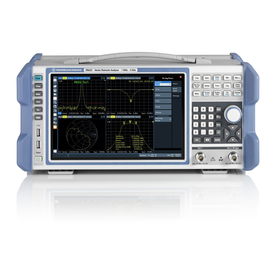
® Instrument Tour R&S ZNLE Front Panel View Instrument Tour Front Panel View This chapter describes the front panel, including all function keys and connectors. Figure 4-1: Front panel view 1 = Power key 2 = USB (2.0) connectors 3 = System keys 4 = Touchscreen 5 = Function keys 6 = Keypad... - Page 28 ® Instrument Tour R&S ZNLE Front Panel View ing an alternative means of user interaction for quick and easy handling of the instrument. Figure 4-2: Touchscreen elements 1 = Toolbar with standard application functions, e.g. print, save/open file etc. 2 = Tabs for individual channel setups 3 = Softtool panel (a.k.a.
- Page 29 ® Instrument Tour R&S ZNLE Front Panel View ● Zooming into a diagram ● Selecting a new evaluation method ● Scrolling through a result list or table ● Saving or printing results and settings To imitate a right-click by mouse using the touchscreen, for example to open a context-sensitive menu for a specific item, press the screen for about 1 second.
- Page 30 ® Instrument Tour R&S ZNLE Front Panel View Table 4-1: System keys System key Assigned functions [Preset] Resets the instrument to the default state. [Setup] Provides basic instrument configuration functions, e.g.: ● Reference frequency (external/internal) ● Date, time, display configuration ●...
- Page 31 ® Instrument Tour R&S ZNLE Front Panel View Function key Assigned functions [Mkr] Defines and positions absolute and relative measurement mark- ers (markers and delta markers). Selects special marker functions [Mkr->] Used for search functions of the measurement markers (maxi- mum/minimum of the trace).
- Page 32 ® Instrument Tour R&S ZNLE Front Panel View Type of key Description Unit keys Adds the selected unit to the entered numeric value and com- plete the entry. (G/n, M/μ, k/m, x1) For level entries (e.g. in dB) or dimensionless values, all units have the value "1"...
- Page 33 ® Instrument Tour R&S ZNLE Front Panel View ● For numeric entries: increments (clockwise direction) or decrements (counter- clockwise direction) the instrument parameter at a defined step width ● In lists: toggles between entries ● For markers, limit lines, and other graphical elements on the screen: moves their position ●...
-
Page 34: Rear Panel View
® Instrument Tour R&S ZNLE Rear Panel View The test ports serve as outputs for the RF stimulus signal and as inputs for the measured RF signals from the DUT (response signals). ● With a single test port, it is possible to generate a stimulus signal and mea- sure the response signal in reflection. - Page 35 ® Instrument Tour R&S ZNLE Rear Panel View Figure 4-3: Rear panel view 1 = AC power supply connection and main power switch 2 = GPIB ("IEC") interface 3 = Reference clock connectors 4 = Trigger input connector 5 = "DVI" connector for external display 6 = "LAN"...
- Page 36 ® Instrument Tour R&S ZNLE Rear Panel View 4.2.2 GPIB Interface The optional GPIB interface (R&S FPL1-B10) is in compliance with IEEE488 and SCPI. A computer for remote control can be connected via this interface. To set up the connection, a shielded cable is recommended. 4.2.3 Ref.
- Page 37 ® Instrument Tour R&S ZNLE Rear Panel View twisted-pair category 5 UTP/STP cables in a star configuration (UTP stands for unshielded twisted pair, and STP for shielded twisted pair). For details, see the R&S ZNLE user manual. 4.2.7 The R&S ZNLE is equipped with a network interface and can be connected to an Ethernet LAN (local area network).
- Page 38 ® Instrument Tour R&S ZNLE Rear Panel View The serial number is used to define the default instrument name, which is: <Type><variant>-<serial_number> For example, ZNLE3-123456. The instrument name is required to establish a connection to the instrument in a LAN. Getting Started 1323.2873.02 ─...
-
Page 39: Trying Out The Instrument
® Trying Out the Instrument R&S ZNLE Performing Measurements Trying Out the Instrument This chapter introduces the most important functions and settings of the R&S ZNLE step by step. The complete description of the functionality and its usage is given in the R&S ZNLE User Manual. Basic instrument operation is described in Chapter 6, "Operating the Instrument",... - Page 40 ® Trying Out the Instrument R&S ZNLE Performing Measurements Measurement stages in the wizard The individual dialogs of the "S-Parameter Wizard" correspond to the typical stages of any measurement: 1. Select the test setup. 2. Define port impedances. 3. Select the measurement parameters and the diagrams. 4.
- Page 41 ® Trying Out the Instrument R&S ZNLE Performing Measurements 1. Connect the DUT between test ports 1 and 2 of the network analyzer as shown above. 2. Switch on the instrument and start the VNA application. Proceed as described in Chapter 3.6, "Switching On or Off", on page 16.
- Page 42 ® Trying Out the Instrument R&S ZNLE Performing Measurements transmitted wave at the DUT's output port (port no. 2) to the incident wave at the DUT's input port (port no. 1). The R&S ZNLE automatically adjusts its internal source and receiver to the selected measured quantities: For an S measurement, a stimulus signal (termed a...
- Page 43 ® Trying Out the Instrument R&S ZNLE Performing Measurements 5.1.1.3 Calibrating the Instrument Calibration (system error correction) is the process of eliminating systematic, reproducible errors from the measurement results. E.g., in the current test setup, the connecting cables between the analyzer ports and the DUT introduce an attenuation and a phase shift of the waves.
- Page 44 ® Trying Out the Instrument R&S ZNLE Performing Measurements 4. Select "Next" to proceed to the next page of the "Calibration Setting" wizard. 5. Select the test port connector type and gender (here: N 50 Ω, female, corre- sponding to a male Through standard), and the calibration kit (here: R&S ZV- Z121).
- Page 45 ® Trying Out the Instrument R&S ZNLE Performing Measurements 7. The calibration dock widget indicates the standard measurements that make up a "Trans Norm" calibration. Select "Through (mm)" to initiate the measurement of the connected Through standard. Measuring the isolation between ports 1 and 2 is optional. Skip it for now.
- Page 46 ® Trying Out the Instrument R&S ZNLE Performing Measurements 5.1.1.4 Evaluating Data The analyzer provides various tools to optimize the display and analyze the mea- surement data. For instance, you can use markers to determine maxima and min- ima on the trace, and change the display format to obtain information about the group delay of the transmitted wave.
- Page 47 ® Trying Out the Instrument R&S ZNLE Performing Measurements Refer to the information on trace formats in the help system or in the user manual to learn more about the diagram properties. 5.1.2 Reflection S-Parameter Measurement In a reflection measurement, the analyzer transmits a stimulus signal to the input port of the device under test (DUT) and measures the reflected wave.
- Page 48 ® Trying Out the Instrument R&S ZNLE Performing Measurements You can also use the basic transmission test setup, e.g. if you want to mea- sure reflection and transmission parameters in parallel. ● The analyzer provides special calibration types for reflection measurements. Use the calibration wizard and select an appropriate type.
-
Page 49: Zooming Into The Display
® Trying Out the Instrument R&S ZNLE Zooming into the Display Zooming into the Display To analyze the areas around the peak levels in more detail, we will zoom into a peak. 1. Tap the "Multiple Zoom" icon in the toolbar. The icon is highlighted to indicate that zoom mode is active. -
Page 50: Saving Settings
® Trying Out the Instrument R&S ZNLE Saving Settings Figure 5-2: Zoomed display around a peak Saving Settings To restore the results of our measurements later, we will store the instrument set- tings to a file. To save the instrument settings to a file 1. - Page 51 ® Trying Out the Instrument R&S ZNLE Saving Settings Keep the default "File Type" setting "Instrument with all Channel Setups" to store the configuration of all channel setups. Figure 5-3: Saving the instrument settings to a file 4. Tap the "Save" button. The file MyMultiViewSetup.dfl is stored in the default directory C:\ProgramData\Rohde-Schwarz\ZNL-FPL\Save.
-
Page 52: Printing And Saving Results
® Trying Out the Instrument R&S ZNLE Printing and Saving Results 2. Tap the "Load" icon in the toolbar. 3. In the "Load" dialog box, select the MyMultiViewSetup.dfl file in the default directory C:\ProgramData\Rohde-Schwarz\ZNL-FPL\Save. 4. Tap the "Load" button. All instrument settings are restored and the display should resemble the instrument display right before the settings were stored. - Page 53 ® Trying Out the Instrument R&S ZNLE Printing and Saving Results The screenshot is stored to MyMultiViewDisplay.png. Getting Started 1323.2873.02 ─ 08...
-
Page 54: Operating The Instrument
® Operating the Instrument R&S ZNLE Understanding the Display Information Operating the Instrument This chapter provides an overview on how to work with the R&S ZNLE. Remote control In addition to working with the R&S ZNLE interactively, located directly at the instrument, it is also possible to operate and control it from a remote PC. - Page 55 ® Operating the Instrument R&S ZNLE Understanding the Display Information 1 = Window title bar with measurement-specific (trace) information 2 = Diagram area with marker information 3 = Diagram footer with diagram-specific information Window title bar For each parameter diagram, a window is displayed with the following information in the title bar: 1 = Trace name 2 = Measured parameter...
-
Page 56: Accessing The Functionality
® Operating the Instrument R&S ZNLE Accessing the Functionality Diagram footer For each parameter diagram, a window is displayed with the following information in the footer: 1 = Channel 2 = Center frequency 3 = Power level 4 = Measurement bandwidth 5 = Span Accessing the Functionality All tasks necessary to operate the instrument can be performed using this user... - Page 57 ® Operating the Instrument R&S ZNLE Accessing the Functionality 6.2.1 Toolbar Functions Standard functions can be performed via the icons in the toolbar at the top of the screen. You can hide the toolbar display, e.g. when using remote control, to enlarge the display area for the measurement results ("Setup"...
- Page 58 ® Operating the Instrument R&S ZNLE Accessing the Functionality The undo function is useful, for example, if you are performing a zero span mea- surement with several markers and a limit line defined and accidentally select a different measurement. In this case, many settings would be lost. However, if you press [UNDO] immediately afterwards, the previous status is retrieved, i.e.
- Page 59 ® Operating the Instrument R&S ZNLE Accessing the Functionality 6.2.2 Softtools Softtools display groups of related settings as a tabbed panel. They can be opened via function keys on the (virtual) front panel, or via context menu items. Figure 6-1: Scale softtool The softtools are displayed in the softkey bar of the instrument.
- Page 60 ® Operating the Instrument R&S ZNLE Accessing the Functionality 6.2.3 Context Menus Several items in the diagram area have context menus (for example markers, traces or the channel bar). If you right-click on one of these items (or tap it for about 1 second), a menu is displayed which contains the same functions as the corresponding softkey.
-
Page 61: Entering Data
® Operating the Instrument R&S ZNLE Entering Data The on-screen keyboard display can be switched on and off as desired using the "On-Screen Keyboard" function key beneath the screen. When you press this key, the display switches between the following options: ●... - Page 62 ® Operating the Instrument R&S ZNLE Entering Data Transparent dialog boxes You can change the transparency of the dialog boxes to see the results in the windows behind the dialog box. Thus, you can see the effects that the changes you make to the settings have on the results immediately. To change the transparency, select the transparency icon at the top of the dialog box.
-
Page 63: Touchscreen Gestures
® Operating the Instrument R&S ZNLE Touchscreen Gestures Correcting an entry 1. Using the arrow keys, move the cursor to the right of the entry you want to delete. 2. Press the [Backspace] key. The entry to the left of the cursor is deleted. 3. - Page 64 ® Operating the Instrument R&S ZNLE Touchscreen Gestures Double-tapping Tap the screen twice, in quick succession. Double-tap a diagram or the window title bar to maximize a window in the display, or to restore the original size. Dragging Move your finger from one position to another on the display, keeping your finger on the display the whole time.
- Page 65 ® Operating the Instrument R&S ZNLE Touchscreen Gestures Figure 6-4: Pinching Figure 6-5: Spreading Touch gestures in diagrams change measurement settings When you change the display using touch gestures, the corresponding measurement settings are adapted. This is different to selecting an area on the screen in zoom mode, where merely the resolution of the displayed trace points is changed temporarily (graphical zoom).
-
Page 66: Getting Help
® Operating the Instrument R&S ZNLE Getting Help Mouse operation Touch operation Drag-&-drop (= click and hold, then drag and Touch, then drag and release release) Mouse wheel to scroll up or down Swipe Dragging scrollbars to scroll up or down, left or Swipe right In (graphical) Zoom mode only: dragging the... - Page 67 ® Operating the Instrument R&S ZNLE Getting Help If no context-specific help topic is available, a more general topic or the "Con- tent" tab is displayed. For standard Windows dialog boxes (e.g. File Properties, Print dialog etc.), no context-sensitive help is available. To display a help topic for a screen element not currently focused 1.
-
Page 68: Customer Support
® Customer Support R&S ZNLE Collecting Information for Support Customer Support Collecting Information for Support If problems occur, the instrument generates error messages which in most cases will be sufficient for you to detect the cause of an error and find a remedy. Error messages are described in the "Troubleshooting"... - Page 69 ® Customer Support R&S ZNLE Collecting Information for Support To collect the support information 1. Press the [Setup] key. 2. Select "Service" > "R&S Support" and then "Create R&S Support Information". The file is stored as C:\Program Files\Rohde-Schwarz\Vector Network Analyzer\ZNL\ user\<inst_model>_<serial-no>_<date_and_time>.zip For example C:\Program Files\Rohde-Schwarz\Vector Network Analyzer\ZNL\...
-
Page 70: Contacting Customer Support
® Customer Support R&S ZNLE Contacting Customer Support Figure 7-1: Event Viewer 5. Enter a file name and select "Save" Collect the error information and attach it to an email in which you describe the problem. Send the email to the customer support address for your region as listed Chapter 7.2, "Contacting Customer Support", on page 70. - Page 71 ® Customer Support R&S ZNLE Contacting Customer Support Contact information Contact our customer support center at www.rohde-schwarz.com/support, or fol- low this QR code: Figure 7-2: QR code to the Rohde & Schwarz support page Getting Started 1323.2873.02 ─ 08...
-
Page 72: Index
® Index R&S ZNLE Index Function keys Details - see user manual ....30 Alphanumeric parameters ....... 62 Overview ..........30 Application cards ........11 Application notes ........11 Arrow keys ..........33 Getting started ........... 9 GPIB interface Configuring - see user manual ....36 Brochures .......... - Page 73 ® Index R&S ZNLE Navigation Technical support ........68 Controls ..........32 Touchscreen in tables ..........32 Overview ..........27 Navigation keys ........33 Transmission measurement (example) ... 40 Numeric parameters ........ 62 Trigger In Connector ........... 36 Trying out Prerequisites ........
Need help?
Do you have a question about the ZNLE Series and is the answer not in the manual?
Questions and answers