
Related Manuals for GE PROFILE TCX18I


Summary of Contents for GE PROFILE TCX18I
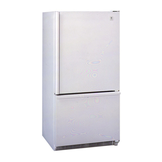
- Page 1 GE Consumer Service Training TECHNICAL SERVICE GUIDE GE PROFILE BOTTOM-FREEZER NO-FROST REFRIGERATOR MODELS: TCX18I TCX18P PUB # 31-9024 03/99...
-
Page 2: Table Of Contents
CONTENTS SAFETY INFORMATION .......................... NOMENCLATURE ............................ FEATURES AND BENEFITS ........................WARRANTY ............................. SERVICE SPECIFICATIONS ........................RESISTANCES/FAST MOVING PARTS ....................PRODUCT FAMILARIZATION AND CARE ..................... 11-14 DOOR REVERSE ............................. 15-18 COMPONENT SERVICEABILITY ......................19-24 Gaskets-Shelves ............................Roller System, Operating requirements ....................Airflow-Evaporator Fan .......................... -
Page 3: Safety Information
IMPORTANT SAFETY NOTICE The information in this service guide is intended for use by individuals possessing adequate backgrounds of electrical, electronic and mechanical experience. Any attempt to repair a major appliance may result in personal injury and property damage. The manufacturer or seller cannot be responsible for the interpretation of this information, nor can it assume any liability in connection with it's use. -
Page 4: Nomenclature
Model TCX18 is a bottom freezer, no frost 18 cubic foot refrigerator, introduced 1999. X 18 P A C B ENGINEERING DESIGN/ REVISION A - Intial design BRAND / PRODUCT B - First Revision T-GE Refrigerator MODEL YEAR CONFIGURATION C - 1999 ICEMAKER/DISPENSER/ Energy EXTERIOR H - High Efficiency R - Cube, Crushed &... - Page 8 ADJUSTABLE SHELVES INSERT TOP HOOK...
-
Page 9: Warranty
One Year materials or workmanship. During this full one-year From the date of the warranty. Ge will also provide, free of charge, all labor original purchase and in-home service to replace the defective part. Any part of the sealed refrigerating system (the... -
Page 10: Service Specifications
SPECIFICATIONS (TECHNICAL DATA) ELECTRICAL SPECIFICATIONS Temperature Control (Position 5) 35-40 Defrost Control 10 hrs. @ 40 min. Defrost Thermostat 55-25 Electrical Rating: 115V, AC 60 Hz. 3-6.Amp. Maximum Current Leakage 0.35 mA Maximum Ground Path Resistance 0.5 Ohms Energy Consumption 699 KWH/YEAR NO LOAD PERFORMANCE Control Position... -
Page 11: Resistances/Fast Moving Parts
COMPONENT RESISTANCE 190 Ω WATER VALVE FAN MOTOR 205 Ω (Condenser) FAN MOTOR 48.3 Ω (Evaporator) 28.5 Ω DEFROST HEATER WATER VALVE 190 Ω (WHEN USED) -
Page 12: Product Familarization And Care
The temperature controls on the refrig- If you want colder or warmer temperatures, erator have letters and numbers. Ini- adjust therefrigerator temperature firstWhen tially set the refrigerator control at 5 satisfied with that, adjust the freezer tempera- and the freezer control at C. ture. - Page 13 Refrigerator shelves, bins and storage drawers. Not all features are on all models. Rearranging the Shelves Glass and wire shelves in the refrigerator compartment are adjustable. To Remove To Replace Slide-Out Spillproof Shelf The slide-out spillproof shelf Make sure you push the shelves all the way back allows you to reach items stored in before you close the door.
- Page 14 Adjustable Humidity Drawers Slide the control all the way to MIN Slide the control all the way to the MAX set- setting to provide lower humidity ting to provide high humidity recommended levels recommended for most for most vegetables fruits. Detachable Meat Drawer The drawer and the adjustable shelf to which it attaches can be relocated...
- Page 15 Some models may have a automatic icemaker. The correct kit model is noted on the back of the refrigera- tor. NOTE: Refrigerator shold be installed in an area when the external temperature range falls between 60 F-105 F. If the temperature is below 60 F, it will not run often enough to maintain proper temperature.
-
Page 16: Door Reverse
Reversing Door Swing • Read instructions all the way through. • Handle all parts with care to prevent scratching. NOTE: Stainless steel dor handles are NOT reversible. TOOLS REQUIRED: Masking tape Phillips screwdriver Putty knife or thin blade screwdriver Square head #2 screwdriver 7/32”, 5/16”... - Page 17 Reversing the Hardware Transfer Bottom Hinge Bracket to the Left * Pull out grille 1” and set it down n the floor to gain access to hinge bracket screws. BOTTOM RIGHT * Using a 3/8” socket, remove the hinge bracket, screws, plastic washer and spacer shim from the bottom right side of the cabinet.
- Page 18 DOOR STOP Transfer Door Stops WASHER WASHER One each door remove the metal stop. Use the center hinge pin as a guide to align the door stop on the opposite side, after reversing the handles. LEFT SIDE RIGHT SIDE REVERSING DOOR HANDLES Transfer the Refrigerator Door Handle to the Right * Remove the four handle mounting screws.
- Page 19 PLASTIC WASHER REVERSING DOOR THE DOOR SWING HINGE Rehang Freezer Door * Lower bottom socket of freezer door onto CENTER bottom hinge bracket. Be sure HINGE washer is in place. BRACKET * Tilt door toward cabinet and gently push door under center hinge bracket and align with the hole in the center hinge bracket.
-
Page 20: Component Serviceability
COMPONENT SERVICABILITY FRESH FOOD AND FREEZER DOORS Doors are basic in construction consisting of steel external panels, with foamed in insulation, plastic liner, shelves (narrow and wide), with endcaps. Door gasket is attached to door panel screws through a steel retainer strip which holds the gasket in place. To replace door gasket: 1. -
Page 21: Roller System, Operating Requirements
COMPONENT SERVICABILITY ADJUSTING ROLLERS The leveling systems includes adjustable legs at front corners which are turned clockwise to raise the refrigera- tor and counterclockwise to lower it. To adjust rollers: 1. The base grill shown in illustration is held in place by a spring, tilt the base grille out exposing the adjustment screws. -
Page 22: Airflow-Evaporator Fan
COMPONENT SERVICABILITY AIRFLOW Fresh Food Compartment Cold air from the evaporator in under the fresh food floor is sent up a channel to the fresh food compart- ment and circulated as mixed air. It then falls through the fresh food compartment until it is drawn in the air return duct at the front of the fresh food floor. -
Page 23: Control Console
COMPONENT SERVICABILITY AIR DIFFUSER DAMPER ASSEMBLY CONTROL CONSOLE TEMPERATURE CONTROL Control console is mounted at top rear of the fresh food compartment. It covers the damper assembly, and CONTROL CONSOLE houses the fresh food and freezer controls. A jumper hole is provided on the left side underneath to advance the timer should diagnostics be required. -
Page 24: Defrost System
COMPONENT SERVICABILITY DEFROST SYSTEM LIGHT The defrost heater is a radiant tube type located SWITCH FOR between the sprial evaporator coils. Heater is FREEZER CMPT. covered by a metal evaporator heater shield, and has MULLION two metal tabs (one on either end) that hold the shield and heater in place. -
Page 25: Refrigeration System
COMPONENT SERVICABILITY REFRIGERATION SYSTEM The refrigeration system consist of compressor, condenser fan, evaporator, evaporator fan, filter dryer, and hot loop. Components are changed individually, excepting the lines foamed in the back shown in the illustration below. Parts catalog is provided in the back of this service guide to assist in ordering those parts. The sys- tems uses R-134a (3.5 oz.). -
Page 26: Troubleshooting
TROUBLESHOOTING: Reduce fill time to prevent cubes from being too Crushed Ice Dispenser filling with cubes strongly joined together. Make sure door seal retainer screws are driven Leaks or sweats at gasket down completely. Place a slight pressure on air duct cover, if the noise stops, it is the air duct cover. -
Page 27: Schematic
SCHEMATIC... -
Page 28: Wiring Diagram
WIRING DIAGRAM... - Page 29 EXPLODED DIAGRAMS AND PARTS...
- Page 41 WR86X10006 Dryer...
Need help?
Do you have a question about the PROFILE TCX18I and is the answer not in the manual?
Questions and answers