
Subscribe to Our Youtube Channel
Related Manuals for Daikin FTXV25AV1B


Summary of Contents for Daikin FTXV25AV1B
- Page 1 SiK011003 Draft Inverter Pair Wall Mounted Type FTXV-AB Series [Applied Models] Inverter Pair : Heat Pump...
- Page 2 SiK011003 Inverter Pair Wall Mounted Type FTXV-AB Series Heat Pump Indoor Unit FTXV25AV1B FTXV35AV1B FTXV50AV1B FTXV60AV1B ATXV25AV1B ATXV35AV1B ATXV50AV1B ATXV60AV1B Outdoor Unit RXV25AV1B RXV35AV1B RXV50AV1B RXV60AV1B ARXV25AV1B ARXV35AV1B ARXV50AV1B ARXV60AV1B Table of Contents...
-
Page 3: Table Of Contents
SiK011003 1. Introduction ................................iii 1.1 Safety Cautions ..............................iii 1.2 Used Icons................................vii Part 1 Specifications ................1 1. Specifications ................................2 1.1 25 Class................................2 1.2 35 Class................................4 1.3 50 Class................................6 1.4 60 Class................................8 Part 2 Part Outline and Installation Dimension .......10 1. Part Name ................................11 2. -
Page 4: Introduction
SiK011003 Introduction 1. Introduction 1.1 Safety Cautions Cautions and Be sure to read the following safety cautions before conducting repair work. The caution items are classified into “ Warning ” and “ Caution ”. The “ Warning ” Warnings items are especially important since they can lead to death or serious injury if they are not followed closely. - Page 5 Introduction SiK011003 Warning Be sure to wear a safety helmet, gloves, and a safety belt when working at a high place (more than 2 m). Insufficient safety measures may cause a fall accident. In case of R-410A refrigerant models, be sure to use pipes, flare nuts and tools for the exclusive use of the R-410A refrigerant.
- Page 6 SiK011003 Introduction 1.1.2 Cautions Regarding Safety of Users Warning Be sure to use parts listed in the service parts list of the applicable model and appropriate tools to conduct repair work. Never attempt to modify the equipment. The use of inappropriate parts or tools may cause an electrical shock, excessive heat generation or fire.
- Page 7 Introduction SiK011003 Warning Check to make sure that the power cable plug is not dirty or loose, then insert the plug into a power outlet securely. If the plug has dust or loose connection, it may cause an electrical shock or fire. Be sure to install the product correctly by using the provided standard For unitary type installation frame.
-
Page 8: Used Icons
SiK011003 Introduction Caution Be sure to measure the insulation resistance after the repair, and make sure that the resistance is 1 MΩ or higher. Faulty insulation may cause an electrical shock. Be sure to check the drainage of the indoor unit after the repair. Faulty drainage may cause the water to enter the room and wet the furniture and floor. - Page 9 SiK011003 Part 1 Specifications 1. Specifications........................2 1.1 25 Class..........................2 1.2 35 Class..........................4 1.3 50 Class..........................6 1.4 60 Class..........................8 Specifications...
-
Page 10: Part 1 Specifications
SiK011003 1. Specifications 1.1 25 Class Model FTXV25AV1B/RXV25AV1B ATXV25AV1B/ARXV25AV1B Product Code CB141000300_L08682 CB141000300_L07769 Rated Voltage 220-240 220-240 Power Rated Frequency Supply Phases Power Supply Mode Indoor Indoor Cooling Capacity (Min~Max) 2.65(0.6~3.2) 2.65(0.6~3.2) Heating Capacity(Min~Max) 2.8(0.8~3.6) 2.8(0.8~3.6) Cooling Power Input(Min~Max) 0.89(0.185~1.3) 0.89(0.185~1.3) - Page 11 SiK011003 Model of Outdoor Unit RXV25AV1B ARXV25AV1B Product Code CB141W00300_L08682 CB141W00300_L07769 Compressor Model QXA-A091zE190A QXA-A091zE190A Compressor Oil 68EP 68EP Compressor Type Rotary Rotary L.R.A. 16.5 16.5 Compressor RLA Compressor Power Input Overload Protector 1NT11L-6233 1NT11L-6233 Throttling Method Electron expansion valve Electron expansion valve Operation temp 16~30...
-
Page 12: Class
SiK011003 1.2 35 Class Model FTXV35AV1B/RXV35AV1B ATXV35AV1B/ARXV35AV1B Product Code CB141000400_L08682 CB141000400_L07769 Rated Voltage 220-240 220-240 Power Rated Frequency Supply Phases Power Supply Mode Indoor Indoor Cooling Capacity (Min~Max) 3.4(0.6~3.9) 3.4(0.6~3.9) Heating Capacity(Min~Max) 3.84(0.88~4.4) 3.84(0.88~4.4) Cooling Power Input(Min~Max) 1.33(0.185~1.4) 1.33(0.185~1.4) Heating Power Input(Min~Max) 1.23(0.25~1.55) 1.23(0.25~1.55) Cooling Power Current... - Page 13 SiK011003 Model of Outdoor Unit RXV35AV1B ARXV35AV1B Product Code CB141W00400_L08682 CB141W00400_L07769 Compressor Model QXA-A091zE190A QXA-A091zE190A Compressor Oil 68EP 68EP Compressor Type Rotary Rotary L.R.A. 16.5 16.5 Compressor RLA Compressor Power Input Overload Protector 1NT11L-6233 1NT11L-6233 Throttling Method Electron expansion valve Electron expansion valve Operation temp 16~30...
-
Page 14: Class
SiK011003 1.3 50 Class Model FTXV50AV1B/RXV50AV1B ATXV50AV1B/ARXV50AV1B Product Code CB141000200_L08682 CB141000200_L07769 Rated Voltage 220-240 220-240 Power Rated Frequency Supply Phases Power Supply Mode Indoor Indoor Cooling Capacity (Min~Max) 5.2(1.26~6) 5.2(1.26~6) Heating Capacity(Min~Max) 5.65(1.12~6.8) 5.65(1.12~6.8) Cooling Power Input(Min~Max) 1.67(0.38~2.65) 1.67(0.38~2.65) Heating Power Input(Min~Max) 1.75(0.35~2.65) 1.75(0.35~2.65) Cooling Power Current... - Page 15 SiK011003 Model of Outdoor Unit RXV50AV1B ARXV50AV1B Product Code CB141W00200_L08682 CB141W00200_L07769 Compressor Model QXA-B141zF030A QXA-B141zF030A Compressor Oil 68EP 68EP Compressor Type Rotary Rotary L.R.A. Compressor RLA Compressor Power Input 1440 1440 1NT11L-6233 or KSD115 C or 1NT11L-6233 or KSD115 C or Overload Protector HPC115/95U1 HPC115/95U1...
-
Page 16: Class
SiK011003 1.4 60 Class Model FTXV60AV1B/RXV60AV1B ATXV60AV1B/ARXV60AV1B Product Code CB141000100_L08682 CB141000100_L07769 Rated Voltage 220-240 220-240 Power Rated Frequency Supply Phases Power Supply Mode Indoor Indoor Cooling Capacity (Min~Max) 6.25(2.53~6.8) 6.25(2.53~6.8) Heating Capacity(Min~Max) 6.75(2.53~7.6) 6.75(2.53~7.6) Cooling Power Input(Min~Max) 2.15(0.6~2.65) 2.15(0.6~2.65) Heating Power Input(Min~Max) 2.28(0.6~2.8) 2.28(0.6~2.8) Cooling Power Current... - Page 17 SiK011003 Model of Outdoor Unit RXV60AV1B ARXV60AV1B Product Code CB141W00100_L08682 CB141W00100_L07769 Compressor Model QXA-B141zF030A QXA-B141zF030A Compressor Oil 68EP 68EP Compressor Type Rotary Rotary L.R.A. Compressor RLA Compressor Power Input 1440 1440 1NT11L-6233 or KSD115 C or 1NT11L-6233 or KSD115 C or Overload Protector HPC115/95U1 HPC115/95U1...
-
Page 18: Part 2 Part Outline And Installation Dimension
SiK011003 Part 2 Part Outline and Installation Dimension 1. Part Name...........................11 2. Outline and Installation Dimension..................12 2.1 Outline and Installation Dimensions of Indoor Unit............12 2.2 Outline and Installation Dimensions of Outdoor Unit............13 Part Outline and Installation Dimension... -
Page 19: Part Name
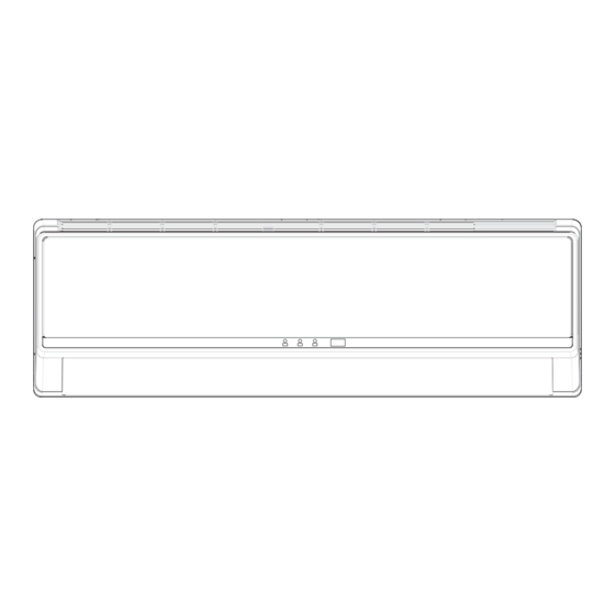
SiK011003 Part Name 1. Part Name Indoor Unit air inlet panel filter aux. button horizontal louver cooling receiver air outlet indicator window display heating power indicator indicator TURBO ON/OFF MODE SAVE SWING SLEEP TIMER LIGHT X-FAN remote controller Outdoor Unit air inlet handle air outlet... -
Page 20: Outline And Installation Dimension
Outline and Installation Dimension SiK011003 2. Outline and Installation Dimension 2.1 Outline and Installation Dimensions of Indoor Unit Air inlet Tube exit 09/12 Class: Rear View 18 Class: 24 Class: Ceiling Over 15 cm Over 15 cm Left Over 15 cm Right Wall-Mounting Plate Unit:mm... -
Page 21: Outline And Installation Dimensions Of Outdoor Unit
SiK011003 Outline and Installation Dimension 2.2 Outline and Installation Dimensions of Outdoor Unit 2.2.1 25/35 Class Unit:mm Drainage pipe Bolt Wrench Part Outline and Installation Dimension... - Page 22 Outline and Installation Dimension SiK011003 2.2.2 50 Class Unit:mm Drainage pipe Bolt Wrench Part Outline and Installation Dimension...
- Page 23 SiK011003 Outline and Installation Dimension 2.2.3 60 Class 1000 Unit:mm Drainage pipe Bolt Wrench Part Outline and Installation Dimension...
-
Page 24: Part 3 Printed Circuit Board Connector Wiring Diagram
SiK011003 Part 3 Printed Circuit Board Connector Wiring Diagram 1. Printed Circuit Board Connector Wiring Diagram..............17 1.1 F(A)TXV25AV1B/F(A)TXV35AV1B..................17 1.2 F(A)TXV50AV1B/F(A)TXV60AV1B..................20 Printed Circuit Board Connector Wiring Diagram... -
Page 25: Printed Circuit Board Connector Wiring Diagram
SiK011003 Printed Circuit Board Connector Wiring Diagram 1. Printed Circuit Board Connector Wiring Diagram 1.1 F(A)TXV25AV1B/F(A)TXV35AV1B Connectors 1) COM-OUT Communication interface 2) L-OUT Interface of outdoor live wire 3) AC-L Interface of indoor live wire 4) CF1 Fan capacitor 5) AIR Interface of outdoor live wire 6) N Neutral Wire... - Page 26 Printed Circuit Board Connector Wiring Diagram SiK011003 PCB Detail PCB : F(A)TXV25AV1B/F(A)TXV35AV1B SW1 PGF SWING-UD SWING-LR JUMP AC-L HUMID L-OUT ROOM TUBE DISP COM-OUT Printed Circuit Board Connector Wiring Diagram...
- Page 27 SiK011003 Printed Circuit Board Connector Wiring Diagram PCB Detail PCB : RXV25AV1B/RXV35AV1B/ARXV25AV1B/ARXV35AV1B OFAN TUPE COMP Printed Circuit Board Connector Wiring Diagram...
-
Page 28: F(A)Txv50Av1B/F(A)Txv60Av1B
Printed Circuit Board Connector Wiring Diagram SiK011003 1.2 F(A)TXV50AV1B/F(A)TXV60AV1B Connectors 1) HEALTH-N Interface of health function neutral wire 2) L-OUT Power supply interface of outdoor live wire 3) AC-L Interface of indoor live wire 4) N Neutral wire 5) FUSE1 Fuse 6) PG Interface of PG motor... - Page 29 SiK011003 Printed Circuit Board Connector Wiring Diagram PCB Detail PCB : F(A)TXV50AV1B/F(A)TXV60AV1B PG HEALTH-L COM-OUT KEY SWING-UD FUSE1 AC-L L-OUT HEALTH-N DISP JUMP TUBE ROOM Printed Circuit Board Connector Wiring Diagram...
- Page 30 Printed Circuit Board Connector Wiring Diagram SiK011003 PCB Detail PCB : RXV50AV1B/RXV60AV1B/ARXV50AV1B/ARXV60AV1B COMP OVC-COMP OFAN INDC Printed Circuit Board Connector Wiring Diagram...
-
Page 31: Part 4 Function And Control
SiK011003 Part 4 Function and Control 1. Function and Control......................24 1.1 F(A)TXV25AV1B/F(A)TXV35AV1B..................24 1.2 F(A)TXV50AV1B/F(A)TTXV60AV1B................28 Function and Control... -
Page 32: Function And Control
Function and Control SiK011003 1. Function and Control 1.1 F(A)TXV25AV1B/F(A)TXV35AV1B Note: Basic functions (the centigrade is used in the following function manual. If there will be Fahrenheit degree, that will be Tf = Tc × 1.8 + 32). Temperature Parameters Indoor preset temperature (Tpreset) Indoor ambient temperature (Tamb.) 1.1.1 Basic Functions... - Page 33 Protection function Overcurrent protection Function and Control SiK011003 If total current is high, the compressor will run in limited frequency. If total current is too high, the compressor will stop, the outdoor fan will delay 30 seconds to stop, indoor unit will display E5 and outdoor yellow light will blink 5 times.
- Page 34 Function and Control SiK011003 In HEAT mode, in order to prevent the indoor unit from blowing out cold wind, each time the compressor starts, the indoor fan will delay 3 minutes after the compressor to run at the latest and it can adjust fan speed automatically when temperature is low. Overcurrent protection Overcurrent protection is the same with that in COOL mode.
- Page 35 Function and Control SiK011003 1.1.6.7 Up & down swing ① After energizing, up & down swing motor will firstly have the horizontal louver rotate anticlockwise to position 0 to close air outlet. If swing function has not been set after turning on the unit, the horizontal louver will turn clockwise to position D in heating mode, or turn clockwise to level position L in other modes.
-
Page 36: F(A)Txv50Av1B/F(A)Ttxv60Av1B
Function and Control SiK011003 1.2 F(A)TXV50AV1B/F(A)TTXV60AV1B 1.2.1 General introduction 1.2.1.1 Display After energizing, the unit will display all icons. Under standby status, running indicating icon is displayed in red. If the unit is started by remote controller, running indicating icon is displayed in green (the color may be different for different models); meanwhile, the icon of current running mode will be displayed (mode icons: cooling, heating and dry mode). - Page 37 Function and Control SiK011003 Start cooling Tamb. Tpreset -0.5˚C Original operating status Tpreset –2 ˚C Stop cooling 7 min. 3 min. 7 min. Graphic instruction: (Same as below) Compressor Indicates operation Outdoor fan motor Indicates stop Indoor fan motor Set fan speed ②...
- Page 38 Function and Control SiK011003 fan motor blows residual heat for a while at set speed to prevent high temperature inside the unit. ◆ When Tset+3.5℃< Tamb. < Tset+5℃ , the unit will maintain its previous operation status. ◆ When the unit stops due to malfunction or protection, the compressor, IDU fan motor and ODU fan motor stop operation. ◆...
- Page 39 Function and Control SiK011003 ◆ Timer ON: If timer ON is set during operation of the unit, the unit will continue to operate. If timer ON is set at unit OFF, upon ON time reaches the unit will start to run according to previous setting status. ◆...
- Page 40 Function and Control SiK011003 ④ Swing function is available only when swing function is set and IDU fan motor is operating. 1.2.3.8 Memory function ① Power failure in unit ON status ◆ Memorized items: unit ON status, mode, up & down swing, light, set temperature, set fan speed, general timer and Fahrenheit/ Celsius. ◆...
-
Page 41: Part 5 Operation Manual
SiK011003 Part 5 Operation Manual 1. System Configuration......................34 2. Operation Manual.......................35 2.1 Operation of Wireless Remote Control................35 Operation Manual... -
Page 42: System Configuration
Operation Manual SiK011003 1. System Configuration After the installation and test operation of the room air conditioner have been completed, it should be operated and handled as described below. Every user would like to know the correct method of operation of the room air conditioner, to check if it is capable of cooling (or heating) well, and to know a clever method of using it. -
Page 43: Operation Manual
Operation Manual SiK011003 2. Operation Manual 2.1 Operation of Wireless Remote Control 2.1.1 Names and Functions of Wireless Remote Control Buttons on remote controller ON/OFF button MODE button +/- button FAN button SWING button SAVE button X-FAN button TIMER button TURBO button SLEEP button LIGHT button... - Page 44 Operation Manual SiK011003 2.1.1.1 ON/OFF button Press this button can turn on or turn off the air conditioner. After turning on the unit, operation indicator " " on indoor unit is ON (green indicator. Color may be different for different models)and indoor unit gives out a sound. 2.1.1.2 MODE button Press this button can select your required operation mode.
- Page 45 Operation Manual SiK011003 Note: ● After starting up X-FAN function, when turning off the unit, indoor fan will continue to operate for a while at low speed to dry the residual water inside the indoor unit. ● When the unit operates under X-FAN mode, press "X-FAN" button can turn off X-FAN function. Indoor fan stops operation immediately. 2.1.1.8 TIMER button ●...
-
Page 46: Part 6 Troubleshooting
SiK011003 Part 6 Troubleshooting 1. Troubleshooting......................39 1.1 Malfunction Display....................39 1.2 Common Section.......................61 Troubleshooting... -
Page 47: Troubleshooting
SiK011003 Troubleshooting 1. Troubleshooting 1.1 Malfunction Function Analysis Malfunction ● When the air conditioner status is abnormal, please refer to the list below for identification of error code. Indoor display ● The indicator diagram on the left is only for reference. Please refer to the actual product for the actual indicator and position. ●... - Page 48 Troubleshooting SiK011003 Error Code List Display Method of Outdoor Display Method of Indoor Unit Unit Indicator has 3 kinds of Indicator Display (during display status and during Malfunction blinking, ON 0.5s and OFF A/C status Possible Causes blinking, ON 0.5s and OFF Name 0.5s) 0.5s...
- Page 49 SiK011003 Troubleshooting Display Method of Outdoor Display Method of Indoor Unit Unit Indicator has 3 kinds of Indicator Display (during display status and during Malfunction blinking, ON 0.5s and OFF A/C status Possible Causes blinking, ON 0.5s and OFF Name 0.5s) 0.5s Operation...
- Page 50 Troubleshooting SiK011003 Display Method of Outdoor Display Method of Indoor Unit Unit Indicator has 3 kinds of Indicator Display (during display status and during Malfunction blinking, ON 0.5s and OFF A/C status Possible Causes blinking, ON 0.5s and OFF Name 0.5s) 0.5s Operation...
- Page 51 SiK011003 Troubleshooting Display Method of Outdoor Display Method of Indoor Unit Unit Indicator has 3 kinds of Indicator Display (during display status and during Malfunction blinking, ON 0.5s and OFF A/C status Possible Causes blinking, ON 0.5s and OFF Name 0.5s) 0.5s Operation...
- Page 52 Troubleshooting SiK011003 Display Method of Outdoor Display Method of Indoor Unit Unit Indicator has 3 kinds of Indicator Display (during display status and during Malfunction blinking, ON 0.5s and OFF A/C status Possible Causes blinking, ON 0.5s and OFF Name 0.5s) 0.5s Operation...
- Page 53 SiK011003 Troubleshooting Display Method of Outdoor Display Method of Indoor Unit Unit Indicator has 3 kinds of Indicator Display (during display status and during Malfunction blinking, ON 0.5s and OFF A/C status Possible Causes blinking, ON 0.5s and OFF Name 0.5s) 0.5s Operation...
- Page 54 Troubleshooting SiK011003 Display Method of Indoor Unit Display Method of Outdoor Unit Indicator Display (during Indicator has 3 kinds of display blinking, ON 0.5s and OFF status and during blinking, ON Malfunction A/C status Possible Causes 0.5s) 0.5s and OFF 0.5s Name Operation Cool...
- Page 55 SiK011003 Troubleshooting Troubleshooting for Main Malfunction (1) Malfunction of Indoor ambient temperature sensor is open,short circuit Malfunction of Indoor evaporator temperature sensor is open,short circuit Indicator Display (during Malfunction blinking, ON 0.5s and OFF 0.5s) Name Operation Cool Heating Start Indicator Indicator Indicator...
- Page 56 Troubleshooting SiK011003 (2) Malfunction of indoor unit motor nofeedback Indicator Display (during Malfunction blinking, ON 0.5s and OFF 0.5s) Start Name Operation Cool Heating Indicator Indicator Indicator Internal motor OFF 3S (fan motor) do and blink While power os off. Stir the blade not operate 11 times with a tool to see whether the...
- Page 57 SiK011003 Troubleshooting (3) Malfunction of Protection of Jumper Cap Indicator Display (during Malfunction blinking, ON 0.5s and OFF 0.5s) Name Operation Cool Heating Start Indicator Indicator Indicator OFF 3S Protection of jumper and blink 15 times Appearance of Is there jumper cap on the the jumper cap mainboard ? Assemble the jumper...
- Page 58 Troubleshooting SiK011003 (4) Communication malfunction Start Disconnect power and check if the connection wire of indoor and outdoor units and the built-in wire of electric box are correctly connected. Connect the wire properly according Is malfunction Correct connection? to the wiring eliminated? diagram.
- Page 59 SiK011003 Troubleshooting (5) Malfunction of Zero-crossing Inspection Circuit Malfunction of the IDU Fan Motor Indicator Display (during Malfunction blinking, ON 0.5s and OFF 0.5s) Name Operation Cool Heating Indicator Indicator Indicator Start Zero-crossing OFF 3S inspection circuit and blink malfunction of the 17 times IDU fan motor Turn power off...
- Page 60 Troubleshooting SiK011003 (6) Malfunction of Overcurrent Protection Main detection points: Is the supply voltage too low with overload? Hardware trouble? Malfunction diagnosis process: Start Is the supply voltage unstable Normal fluctuation should be within 10 % of the Malfunction is with big fluctuation? rated voltage on the nameplate eliminated...
- Page 61 SiK011003 Troubleshooting (7) Capacity charging malfunction (outdoor unit malfunction) (AP1 below means control board of outdoor unit) Main detection points: Detect if the voltage of L and N terminal of XT wiring board is between 210VAC-240VAC by alternating voltage meter; Is reactor (L) well connected? Is connection wire loosened or pulled out? Is reactor (L) damaged? Turn on the unit and wait 1 minute...
- Page 62 Troubleshooting SiK011003 (8) IPM protection, desynchronizing malfunction, overcurrent of compressor phase current(AP1 below means control board of outdoor unit) Main detection points: Is voltage input within the normal range If the control board AP1 is well connected with compressor COMP? If they are loosened? If the connection sequence is correct? Heat exchange of unit is not good (heat exchanger is dirty and unit radiating environment is bad);...
- Page 63 SiK011003 Troubleshooting (9) High temperature and overload protection(AP1 below means control board of outdoor unit) Main detection points: If the outdoor ambient temperature is in normal range; If the indoor and outdoor fan are running normally; If the radiating environment of indoor and outdoor unit is good. Start Normal protection, please If the outdoor...
- Page 64 Troubleshooting SiK011003 (10) Start-up failure(AP1 below means control board of outdoor unit) Main detection points: If the compressor wiring is correct? If the stop time of compressor is suf cient? If the compressor is damaged? If the refrigerant charging amount is too much? Turn on the unit The stop time is not sufficient and If the stop time of compressor...
- Page 65 SiK011003 Troubleshooting (11) Overload and high discharge temperature malfunction Main detection points: If the electronic expansion valve is connected well? Is the electronic expansion valve damaged? If the refrigerant is leaked? The compressor overload protection terminal is not connected well with the mainboard? If the overload protector is damaged? Heat exchange of unit is not good? (heat exchanger is dirty and unit radiating environment is bad) Too much load of the system causes high temperature of compressor after working for a long time?
- Page 66 Troubleshooting SiK011003 Start 30min after power off the unit If the overload protector SAT is well connected? Under ambient temperature, test the resistance of overload protector with ohmmeter; resistance value should be<1000ohm Connect wire If the wiring terminal FA of electronic according to wiring expansion valve is well connected? diagram...
- Page 67 SiK011003 Troubleshooting (12) PFC (correction for power factor) malfunction (outdoor unit malfunction) Main detection points: Check if power plug is connected well with the socket Check if the reactor of outdoor unit is damaged? Malfunction diagnosis process: start If power plug is connected Is the malfunction Connect the plug correctly well with the socket...
- Page 68 Troubleshooting SiK011003 (13) Communication malfunction Main detection points: Check if the connection wire and the built-in wiring of indoor and outdoor unit are connected well and without damage; If the communication circuit of indoor mainboard is damaged? If the communication circuit of outdoor mainboard (AP1) is damaged? Malfunction diagnosis process: Start If the unit operates normally...
-
Page 69: Common Section
SiK011003 Troubleshooting Common Section Measure insulation resistance The breaker trips at once when it to ground to see if there is any is set to “ON”. leakage. Trip of breaker or blow of fuse The circuit or the part of the air conditioner has malfunction. - Page 70 Troubleshooting SiK011003 Improper set of temperature Adjust set temperature If cooling (heating) load Check the forecasted load of cooling (heating) is proper Check and fill the leakage, then The refrigerant has leakage or is vacuumize it and supplement the insufficient refrigerant as required Leakage between the high pres- Replace the compressor...
- Page 71 SiK011003 Troubleshooting The indoor fan motor is burned or breaks or has the heat protector Replace the fan motor or the defective part. malfunction. The built-in heat protector of the The fan does not motor breaks frequently because the Replace the fan motor run when it is set motor is abnormal.
- Page 72 Troubleshooting SiK011003 The torque of the swing motor is not enough First, check whether the connection is Wrong connection The swing fan wrong. If no, replace the parts does not run. The Main board is damaged The Main board malfunction Change the Main board In cool, heat mode, the...
-
Page 73: Part 7 Appendix
SiK011003 Part 7 Appendix 1. Wiring Diagram........................66 1.1 25 Class..........................66 1.2 35 Class..........................67 1.3 50 Class..........................68 1.4 60 Class..........................69 2. Exploded View and Parts List.....................70 2.1 Indoor Unit.........................70 2.2 Outdoor Unit........................77 3. Piping diagram ....................84 Appendix... -
Page 74: Wiring Diagram
Appendix SiK011003 1. Wiring Diagram 1.1 25 Class FTXV25AV1B,RXV25AV1B ATXV25AV1B,ARXV25AV1B Appendix... -
Page 75: Class
SiK011003 Appendix 1.2 35 Class FTXV35AV1B,RXV35AV1B ATXV35AV1B,ARXV35AV1B Appendix... -
Page 76: Class
Appendix SiK011003 1.3 50 Class FTXV50AV1B,RXV50AV1B ATXV50AV1B,ARXV50AV1B Appendix... -
Page 77: Class
SiK011003 Appendix 1.4 60 Class FTXV60AV1B,RXV60AV1B ATXV60AV1B,ARXV60AV1B Appendix... -
Page 78: Exploded View And Parts List
Appendix SiK011003 2. Exploded View and Parts List 2.1 Indoor Unit FTXV25AV1B/ATXV25AV1B FTXV35AV1B/ATXV35AV1B Appendix... - Page 79 SiK011003 Appendix 25 Class Part Code Description FTXV25AV1B ATXV25AV1B Product Code CB141N00300_L08682 CB141N00300_L07769 Front Panel Sub-Assy 00015500001_L08682 00015500001_L07769 Filter Sub-Assy 1112220403 1112220403 Screw Cover 24252016 24252016 Electric Box Cover2 20122075 20122075 Front Case Sub-assy 20012139 20012139 Guide Louver 10512157 10512157...
- Page 80 Appendix SiK011003 35 Class Part Code Description FTXV35AV1B ATXV35AV1B Product Code CB141N00400_L08682 CB141N00400_L07769 Front Panel Sub-Assy 00015500001_L08682 00015500001_L07769 Filter Sub-Assy 1112220403 1112220403 Screw Cover 24252016 24252016 Electric Box Cover2 20122075 20122075 Front Case Sub-assy 20012139 20012139 Guide Louver 10512157 10512157 Helicoid Tongue 26112163 26112163...
- Page 81 SiK011003 Appendix FTXV50AV1B/ATXV50AV1B Appendix...
- Page 82 Appendix SiK011003 50 Class Part Code Description FTXV50AV1B ATXV50AV1B Product Code CB141N00200_L08682 CB141N00200_L07769 Front Panel Assy 00000300002_L08682 00000300002_L07769 Display Board 30565267 30565267 Filter Sub-Assy 1112208901 1112208901 Screw Cover 24252016 24252016 Front Case Sub-Assy 20022172 20022172 Guide Louver 10512115 10512115 Air Louver 1 10512116 10512116 Air Louver 2...
- Page 83 SiK011003 Appendix FTXV60AV1B/ATXV60AV1B Appendix...
- Page 84 Appendix SiK011003 60 Class Part Code Description FTXV60AV1B ATXV60AV1B Product Code CB141N00200_L08682 CB141N00200_L07769 Front Panel Assy 00000300002_L08682 00000300002_L07769 Filter Sub-Assy 30565267 30565267 Screw Cover 1112208901 1112208901 Front Case Assy 24252016 24252016 Air Louver 1 20022172 20022172 Helicoid Tongue 10512115 10512115 Left Axile Bush 10512116 10512116...
-
Page 85: Outdoor Unit
SiK011003 Appendix 2.2 Outdoor Unit RXV25AV1B/ARXV25AV1B RXV35AV1B/ARXV35AV1B Appendix... - Page 86 Appendix SiK011003 25 Class Part Code Description RXV25AV1B ARXV25AV1B Product Code CB141W00300_L08682 CB141W00300_L07769 Front Grill 22413008 22413008 Front Panel 01533034P 01533034P Axial Flow Fan 10333004 10333004 Chassis Sub-assy 02803037P 02803037P Fan Motor 1501308506 1501308506 Top Cover Sub-Assy 01253073 01253073 Motor Support 01703104 01703104 Electric Box Assy...
- Page 87 SiK011003 Appendix 35 Class Part Code Description RXV35AV1B ARXV35AV1B Product Code CB141W00400_L08682 CB141W00400_L07769 Front Grill 22413008 22413008 Front Panel 01533034P 01533034P Axial Flow Fan 10333004 10333004 Chassis Sub-assy 02803151P 02803151P Fan Motor 1501308506 1501308506 Top Cover Sub-Assy 01253073 01253073 Motor Support 0170310401 0170310401 Electric Box Assy...
- Page 88 Appendix SiK011003 RXV50AV1B/ARXV50AV1B 10 11 12 13 Appendix...
- Page 89 SiK011003 Appendix 50 Class Part Code Description RXV50AV1B ARXV50AV1B Product Code CB141W00200_L08682 CB141W00200_L07769 Front Grill 22415002 22415002 Front Panel 01535013 01535013 Electrical Heater (Chassis) Drainage Connecter 06123401 06123401 Chassis Sub-assy 02803231P 02803231P Drainage hole Cap 06813401 06813401 Compressor and fittings 00105249G 00105249G Magnet Coil...
- Page 90 Appendix SiK011003 RXV60AV1B/ARXV60AV1B 9 10 11 12 13 14 15 Appendix...
- Page 91 SiK011003 Appendix 60 Class Part Code Description RXV60AV1B ARXV60AV1B Product Code CB141W00100_L08682 CB141W00100_L07769 Front Grill 22415003 22415003 Cabinet 01435004P 01435004P Left Handle 26235401 26235401 Front Side Plate 01305086P 01305086P Drainage Connecter 06123401 06123401 Chassis Sub-assy 02803255P 02803255P Drainage hole Cap 06813401 06813401 Gas-liquid Separator Assy...
-
Page 92: Piping Diagram
Appendix SiK011003 3. Piping Diagram 25/35 Class Indoor unit Outdoor unit Gas pipe side Valve 4-Way valve Di s charge Heat Suction Accumlator exchanger Compressor (evaporator) Heat exchanger Liquid pipe (condenser) side Valve Strainer Electron Strainer expansion valve COOLING HEATING 50/60 Class Outdoor unit Indoor unit... - Page 93 Daikin Industries, Ltd.’s products are manufactured for export to numerous countries throughout the Warning world. Daikin Industries, Ltd. does not have control over which products are exported to and used in a particular country. Prior to purchase, please therefore confirm with your local authorised importer, distributor and/or retailer whether this product conforms to the applicable standards, and is suitable for use, in the region where the product will be used.
Need help?
Do you have a question about the FTXV25AV1B and is the answer not in the manual?
Questions and answers