Table of Contents
Advertisement
Quick Links
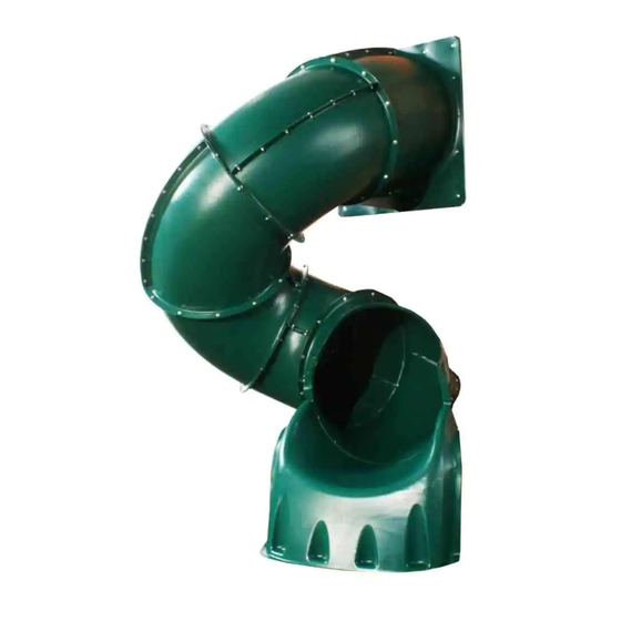
5' Turbo Tube Slide
Note: This accessory is designed to fit a 5' Deck height only.
C A U T I O N
•
Do not climb on the
outside of the slide
• This slide is designed for
home use only, not for
Public Playgrounds
• Product intended for
children ages from 2-10
years old.
WARNING:
!
Assembly by an adult.
Please make sure all lumber, hardware and accessory parts are accounted for. If you are missing
DO NOT RETURN
anything, please
To register your product and download unit specific Turbo Tube Slide instructions,
Other benefits include information on product warranties, assembly plan updates, joining our mailing
list for new products and promotions, and providing feedback on products.
ASSEMbly INSTRUCTIONS
IMPORTANT!!
PLEASE READ BEFORE BEGINNING ASSEMBLY!!
Service Department at the number below.
http://www.swing-n-slide.com
Swing•N•Slide • 1212 Barberry Drive • Janesville, Wisconsin 53545
Visit our web site at: www.swing-n-slide.com or call us at
1-800-888-1232
to the store where purchased. Please call our Customer
visit:
Advertisement
Table of Contents

Subscribe to Our Youtube Channel
Related Manuals for Swing-N-Slide NE 4692-T


Summary of Contents for Swing-N-Slide NE 4692-T
- Page 1 Other benefits include information on product warranties, assembly plan updates, joining our mailing list for new products and promotions, and providing feedback on products. Swing•N•Slide • 1212 Barberry Drive • Janesville, Wisconsin 53545 Visit our web site at: www.swing-n-slide.com or call us at 1-800-888-1232...
- Page 2 Turbo Tube Slide Dimensions 48-1/4'' 63-1/8'' 32''...
- Page 3 Proper Placement of Turbo Tube Slide on The Tower Option 3 Swing beam Safety Zone Swing beam Option 2 47-1/2'' Swing beam Safety Zone Option 1 NOTE: This diagram is based on a 47-1/2’’ square deck.
- Page 4 Safety Checklist for Swing-N-Slide Play Sets and ccessories Observing the following statements and warnings reduces the likelihood of serious or fatal injury Installation Safety – Have You: Consulted the assembly instructions supplied with your particular model? Noted this accessory is to be used only on Swing•N•Slide approved designs? (Do not alter its design or add/remove components.) Made sure all hardware is tightened securely? (Supplied bolt covers must also be fastened securely.)
- Page 5 Swing-N-Slide® will repair, or at its discretion, replace any part within the stated warranty period which is defective in workmanship or materials. This decision is subject to verification of the defect upon delivery of the defective part to Swing-N-Slide® at 1212 Barberry Drive, Janesville, Wisconsin, 53545. Any part(s) returned to Swing-N- Slide®...
- Page 6 ssembly Instructions TOOLS REQUIRED CIRCUlAR SAW DRIll 1/2" SOCKET & WRENCH TAPE MEASURE WRENCH SAFETy GlASSES SQUARE & DUST MASK HARDWARE INClUDED (2) 2" Wood Screw (119) 5/16'' x 3/4" Hex Head Bolts (70) 2-1/2" Wood Screw (16) 2" Lag Screw (240) 5/16'' Flat Washers (2) 1-1/4'' Lag Screw (119) 5/16'' loc nuts...
- Page 7 ssembly Instructions SlIDE COMPONENTS (1) Entrance Piece LH (1) Entrance Piece RH (9) Elbow (1) Exit Elbow (1) Entrance Bracket (1) Elbow Support Bracket (1) Exit (1) T-Bar Support Bracket...
- Page 8 ssembly Instructions Fig. 1a Hex Head Bolt Washer Fig. 1 Washer Loc Nut Entrance Section - 8 bolts Entrance Bracket ENTR NCE SECTION SSEMBLY NOTES: • At least two individuals are needed to assemble the 5' Turbo Tube Slide. • To aid in aligning holes when assembling sections, insert a screwdriver through adjacent holes to maintain hole alignment.
- Page 9 ssembly Instructions Fig. 2 Fig. 2a Hex Head Bolt Washer Washer Loc Nut Elbow Section - 9 bolts each Flange Opening Fig. 2b Elbow Support FlANGE DETAIl Bracket ELBOW ND EXIT SECTION SSEMBLY Assemble the Elbow Section by securing as shown in (Fig.
- Page 10 ssembly Instructions Fig. 3 Fig. 3a Flange Opening Fig. 3b Hex Head Bolt Washer Washer Elbow Section - 12 bolts Loc Nut Fig. 3c Fig. 3d Flange Opening Hole #1 FlANGE DETAIl Slide Elbows 1. Align the first elbow section to the Entrance Section with the seams aligned and the exit facing downward.
- Page 11 ssembly Instructions Fig. 4 Fig. 4a Hex Head Bolt Washer Washer Loc Nut Elbow Section - 12 bolts Fig. 4c Fig. 4b Flange Opening Hole #1 Slide Elbows 1. Align third elbow so that Hole #1 aligns with the flange opening as shown in (Fig. 4) and (Fig.
- Page 12 ssembly Instructions Fig. 5 Fig. 5a Hex Head Bolt Washer Washer Loc Nut Exit Elbow Section - 12 bolts Fig. 5b Fig. 5c Flange Opening Hole #1 Align Top Edge of Slide Base with Exit Section Seam. Slide Exit 1. Align Exit Elbow Section so that Hole #1 aligns with the opening in the flange, as shown in (Fig.
- Page 13 Fig. 6 NOTE: This plan uses a generic tower to illustrate the 5' Turbo Tube Slide being attached. However, this same procedure is to be used for any Swing-N-Slide 5’ Tower Playset. 3-1/4'' Gap 5' DECK HEIGHT Between Each Barrier Board...
- Page 14 ssembly Instructions Fig. 7 2-1/2'' screws per board Fig. 7a 2-1/2'' screw Slide Barrier Cont. 1. Install (2) 2'' x 4'' x 25'' Boards as shown in (Fig. 7). 2-1/2'' screws per board 2. Install (2) 2'' x 4'' x 23'' Slide Support Boards on the inside of your barrier as shown in (Fig.
- Page 15 ssembly Instructions Fig. 8 2-1/2'' screws per joint 31-1/2'' 2-1/2'' screw Slide Barrier Cont. 1. Install a 2'' x 4'' board, cut to the width of your unit, as shown in (Fig. 8).
- Page 16 ssembly Instructions Fig. 9b Fig. 9a Approximate 1-1/4'' 2'' screw per side 2'' lag screws 1-1/4'' lag screws 5/16'' Flat bRACKET SHOUlD bE TIGHT Washers AGAINST 2'' x 4'' UNDER DECK VIEW FlUSH Fig. 9 FlUSH 5/16'' Flat Washer (12) 2'' lag screws 2'' Lag screw 1-1/4'' Lag screw...
- Page 17 ssembly Instructions SUPPORT ND BR CKET Fig. 10 FIGURE 14 SSEMBLY 2" x 4" x 11-1/4'' 2" x 4" x 8-1/4" 2" x 4" x 18" 2" x 4" x 18" 1. Assemble the support base as shown in (Fig. 10). 2.
- Page 18 Instrucciones de ensamblaje / Instructions d’assemblage ENS MBL JE DEL POYO Y DE L Fig. 10 FIGURE 14 BR Z DER 2" x 4" x 11-1/4'' 2" x 4" x 8-1/4" Ensamble la base del soporte como se muestra en la (Fig. 10). 2"...
- Page 19 Instrucciones de ensamblaje / Instructions d’assemblage Fig. 9b Abertura Fig. 9a 1-1/4" aproximada Espace d’environ 1 1/4 po Tornillo de compresión de 2" arandelas Tornillo de 2" planas por cada lado de 5/16" Vis de 2 po tornillos de Tire-fonds de 2 par côté...
- Page 20 Instrucciones de ensamblaje / Instructions d’assemblage Fig. 8 Tornillos de 2-1/2 Vis de 2 1/2 po par joint 31-1/2'' Tornillo de 2-1/2" Vis de 2 1/2 po Barrera del tobogán (cont.) 1. Instale una tabla de 2" x 4", corte al ancho de su unidad, como se muestra en la (Fig. 8). Construction de la barrière de la glissoire, suite 1.
- Page 21 Instrucciones de ensamblaje / Instructions d’assemblage Fig. 7 Tornillos de 2-1/2" por tabla Vis de 2 1/2 po par planche Fig. 7a tornillo de 2-1/2"/Vis de 2 1/2 po Barrera del tobogán (cont.) 1. Instale las (2) tablas de 2" x 4" x 25" como se Tornillos de muestra en la (Fig.
- Page 22 Turbo Tube de 5’ que está tratando de unir. De todos modos, este mismo procedimiento puede seguirse para cualquier equipo de juego con torre de 5’ de Swing-N-Slide. REMARQUE : Ce plan utilise une tour standard pour illustrer la fixation de la glissoire Turbo Tube de 5 pi.
- Page 23 Instrucciones de ensamblaje / Instructions d’assemblage Fig. 5 Fig. 5a Perno con cabeza hexagonal Boulon à tête hexagonale Arandela Rondelle Arandela Rondelle Tuerca de seguridad Contre-écrou Secciones de codo de salida - 12 pernos Section de sortie – 12 boulons Fig.
- Page 24 Instrucciones de ensamblaje / Instructions d’assemblage Fig. 4 Fig. 4a Perno con cabeza hexagonal Boulon à tête hexagonale Arandela Rondelle Arandela Rondelle Tuerca de seguridad Contre-écrou Sección de codo - 12 pernos Section en coude – 12 boulons Fig. 4c Fig.
- Page 25 Instrucciones de ensamblaje / Instructions d’assemblage Fig. 3 Fig. 3a Apertura de la pestaña Ouverture de bride Fig. 3b Perno con cabeza hexagonal Boulon à tête hexagonale Arandela Rondelle Arandela Rondelle Sección de codo - 12 pernos Tuerca de seguridad Section en coude –...
- Page 26 Instrucciones de ensamblaje / Instructions d’assemblage Fig. 2 Fig. 2a Perno con cabeza hexagonal Boulon à tête hexagonale Arandela Rondelle Arandela Rondelle Tuerca de seguridad Contre-écrou Secciones de 9 codos cada una Section en coude – 9 boulons chacune Apertura de la pestaña Ouverture de bride Fig.
- Page 27 Instrucciones de ensamblaje / Instructions d’assemblage Fig. 1a Perno con cabeza hexagonal Boulon à tête hexagonale Arandela Rondelle Fig. 1 Arandela Rondelle Tuerca de seguridad Contre-écrou Sección de entrada - 8 pernos Section d’entrée – 8 boulons Abrazadera de entrada Fixation d’entrée ENS MBL JE DE L SECCIÓN DE ENTR D NOT S:...
- Page 28 COMPONENTES DEl TObOGÁN / COMPOSANTES DE lA GlISSOIRE (1) Pieza de entrada del lado izquierdo (1) Pieza de entrada del lado derecho (1) Panneau d’entrée gauche (1) Panneau d’entrée droit (9) Codo (1) Codo de salida (9) Coude (1) Coude de sortie (1) Coderas Abrazadera (1) Abrazadera de entrada (1) Fixation d’entrée...
- Page 29 HERR MIENT S REQUERID S / OUTILS REQUIS TAlADRO SIERRA CIRCUlAR CUbOS DE 1/2" CON UNA CINTA MÉTRICA llAVE DE CUbOS SCIE CIRCUlAIRE PERCEUSE RUbAN À MESURER DOUIllE ET ClÉ À MOlETTE DE 1/2 PO GAFAS DE SEGURIDAD llAVE DE CUbOS ESCUADRA y MÁSCARA ANTIPOlVO lUNETTES DE SÉCURITÉ...
- Page 30 DE POR VID DEL F BRIC NTE Swing-N-Slide® garantiza que sus toboganes termoformados y montañas para escalar estarán libres de defectos de mano de obra y materiales, bajo condiciones y uso normales, durante la vida útil del producto. G R NTÍ...
- Page 31 Liste de vérification de sécurité pour les ensembles de jeu et les accessoires Swing-N-Slide tender los siguientes enunciados y advertencias reduce la posibilidad de lesiones graves o fatales. Seguridad durante la instalación – Usted: ¿Ha consultado las instrucciones de ensamblaje suministradas con su modelo en particular? ¿Ha notado que este accesorio se debe usar solamente con diseños aprobados por Swing•N•Slide? (No altere su diseño ni añada/retire componentes).
- Page 32 G R NTIE LIMITÉE DU F BRIC NT Swing-N-Slide® Swing-N-Slide® est fière de la qualité et de la durabilité de ses produits. Notre garantie limitée du fabricant donne l'assurance et démontre notre engagement envers la fabrication d'articles pour terrain de jeu résidentiel de qualité.
- Page 33 Lorsque l’équipement est mis hors service, il doit être démonté et conditionné de sorte qu’aucun danger justifié ne sera présent lors de la mise au rebut de l’ensemble. Important! Instructions supplémentaires de sécurité pour tous les centres de jeu Swing-N-Slide. Conserver ce feuillet d’instruction au cas où vous devriez prendre contact avec le fabricant.
- Page 34 Colocación correcta del tobogán Turbo Tube en la torre Emplacement approprié de la glissoire Turbo Tube sur la tour Opción 3 / Option 3 Zona de seguridad de la viga del columpio Zone de sécurité de la poutre de la balançoire Viga del columpio...
- Page 35 Dimensiones del tobogán Turbo Tube Dimensions de la glissoire Turbo Tube 48-1/4'' 63-1/8'' 32''...
- Page 36 Swing•N•Slide • 1212 Barberry Drive • Janesville, Wisconsin 53545 Visite nuestro sitio Web en: www.swing-n-slide.com o llámenos al Consultez notre site Internet à l’adresse suivante : www.swing-n-slide.com ou téléphonez-nous au 1-800-888-1232 © PlayCore Inc. 2013...
Need help?
Do you have a question about the NE 4692-T and is the answer not in the manual?
Questions and answers