Advertisement
Advertisement
Table of Contents

Related Manuals for Testec TT-SI 9010


Summary of Contents for Testec TT-SI 9010
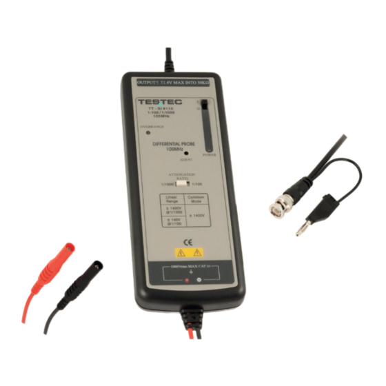
- Page 1 INSTRUCTION MANUAL TT-SI 9010 70MHz Active Differential Probe...
-
Page 2: Safety Terms And Symbols
These probe is in compliance with IEC-61010-031 CAT I, Pollution Degree 2 1. Safety Terms and Symbols Terms appear in this manual: ___________________________________________________ WARNING. Warning statements identify conditions or practice that could result in injury or loss life. ___________________________________________________ CAUTION. Caution statements identify conditions or practice that could result in damage to this product or other property. - Page 3 Must be Grounded This probe is grounded with the shell of BNC connector and an auxiliary grounding terminal, through the grounding conductor of the power cord of the measurement instrument. Before making connections to the input leads of this probe, ensure that the output BNC connector is attached to the BNC connector of the measurement instrument and the auxiliary grounding terminal is connected to a proper ground, while the measurement instrument is properly grounded.
-
Page 4: Installation
4. Installation a. Simply plug-in the BNC output connector to the vertical input of a general purposed oscilloscope or other measurement instrument, and connects the auxiliary grounding terminal to a proper ground. The measurement instrument must have a ground referenced. b. - Page 5 6. Available Power Sources 4 x AA batteries Mains adaptor (6VDC/60mA or regulated 9VDC/40mA), ® ® Lemo Power Cord, for oscilloscopes with power output - Lemo connector. ® ® Probus Power Cord, for oscilloscopes with power output - Probus connector. USB Power Cord, for oscilloscopes which offer USB connector.
-
Page 6: Specifications
8. Specifications TT-SI 9010 Bandwidth DC to 70MHz (-3dB) Attenuation Ratio 1:100 / 1:1000 Accuracy ±2% Rise Time Ω Input Impedance // 10pF each side to ground Input Voltage 1:100 ±700V (DC+peak AC) or 700Vrms - Differential Range 1:1000 ±7000V (DC+peak AC) or 5000Vrms... -
Page 7: Derating Curve
9. Derating Curve The derating curve of the absolute maximum input voltage in common mode is shown as follows. 10. Offset Adjustment If the offset voltage is too large, short the input leads and turn the adjust variable resistor (DC voltage adjustment) which you find in the hole of the panel by using a flat-head screwdriver until the offset voltage is lowest.
Need help?
Do you have a question about the TT-SI 9010 and is the answer not in the manual?
Questions and answers