
Related Manuals for Testec TT-SI 9010A


Summary of Contents for Testec TT-SI 9010A
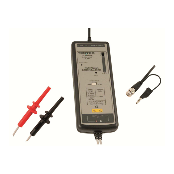
- Page 1 Allice Messtechnik GmbH INSTRUCTION MANUAL TT-SI 9010A 70MHz Active Differential Probe...
- Page 2 www.allice.de Allice Messtechnik GmbH These probe is in compliance with IEC-61010-031 CAT I, Pollution Degree 2 1. Safety Terms and Symbols Terms appear in this manual: ___________________________________________________ WARNING. Warning statements identify conditions or practice that could result in injury or loss life. ___________________________________________________ CAUTION.
- Page 3 www.allice.de Allice Messtechnik GmbH Must be Grounded This probe is grounded with the shell of BNC connector and an auxiliary grounding terminal, through the grounding conductor of the power cord of the measurement instrument. Before making connections to the input leads of this probe, ensure that the output BNC connector is attached to the BNC connector of the measurement instrument and the auxiliary grounding terminal is connected to a proper ground, while the measurement instrument is properly grounded.
- Page 4 www.allice.de Allice Messtechnik GmbH 4. Installation a. Simply plug-in the BNC output connector to the vertical input of a general purposed oscilloscope or other measurement instrument, and connects the auxiliary grounding terminal to a proper ground. The measurement instrument must have a ground referenced. b.
- Page 5 www.allice.de Allice Messtechnik GmbH 6. Offset Adjustment If the offset voltage is too large, short the input leads and turn the adjust variable resistor (DC voltage adjustment) which you find in the hole of the panel by using a flat-head screwdriver until the offset voltage is lowest.
- Page 6 Allice Messtechnik GmbH Specifications TT-SI 9010A Bandwidth DC to 70MHz (-3dB) Attenuation Ratio 1:100 / 1:1000 Accuracy ±2% Rise Time Ω Input Impedance // 10pF each side to ground 1:100 ±700V (DC+peak AC) or 500Vrms Input Voltage 1:1000 ±7000V (DC+peak AC)
- Page 7 www.allice.de Allice Messtechnik GmbH 11. Differential’, Common Mode’ and ‘Absolut max.’ Voltage Range limit is the lesser of the ‘DC+Peak AC’ and RMS values. Input voltage at positive input lead = V(+) / Input voltage at negative input lead = V(-) - Differential Range= V(+) –V(-) - Common Mode Range= [V(+) +V(-) ] /2 The input-specification of differential range and common mode range has to be meet...
- Page 8 www.allice.de Allice Messtechnik GmbH AlliCE Messtechnik GmbH make ALLICE your partner ALLICE Messtechnik GmbH Kelsterbacher Strasse 15-19 60528 Frankfurt am Main Tel.: +49(0)69-67724-583 Fax: +49(0)69-67724-582 info@allice.de www.allice.de © 2018 Allice Messtechnik GmbH – Alle Rechte vorbehalten. © 2018 Allice Messtechnik GmbH – All rights reserved Verwendete Warenzeichen und Schutzrechte sind Eigentum der jeweiligen Hersteller.
Need help?
Do you have a question about the TT-SI 9010A and is the answer not in the manual?
Questions and answers