Table of Contents
Advertisement
Quick Links
Advertisement
Table of Contents
Troubleshooting

Related Manuals for Crestron CN-TVAV


Summary of Contents for Crestron CN-TVAV
- Page 2 This document was prepared and written by the Technical Documentation department at: Crestron Electronics, Inc. 15 Volvo Drive Rockleigh, NJ 07647 1-888-CRESTRON...
-
Page 3: Table Of Contents
Crestron CN-TVAV Contents Programmable TV/AV Controller: CN-TVAV Description Functional Description Physical Description Leading Specifications Setup Cresnet Modular Cabling Cable Configuration for Programming Programming Cable Fabrication Specifications Special Considerations for Using the RS-232 Port for Uploading Programs Cable Configuration for Normal Operation... -
Page 5: Programmable Tv/Av Controller: Cn-Tvav
(herein referred to as the Cresnet system) peripheral or as a “smart” peripheral. As a standard Cresnet system peripheral, the CN-TVAV can be added as a Cresnet network device to a host Crestron control system with all logic, infrared (IR) drivers, and serial strings stored in the control system programming logic. -
Page 6: Physical Description
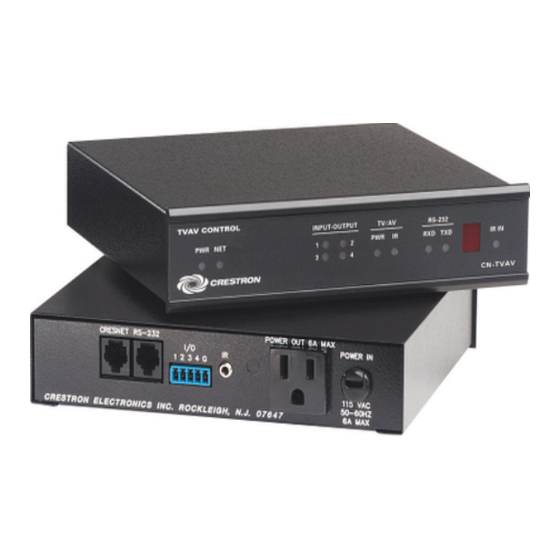
(no IR driver loaded in the CN-TVAV). It is not recommended to communicate to a port of the CN-TVAV (such as the IR Port) through a program in the CN-TVAV itself and via a host control system at the same time. - Page 7 Crestron CN-TVAV CN-TVAV Physical Views CN-TVAV Ports Each CN-TVAV rear panel port has a silk-screened label. For the descriptions of the ports, refer to the two diagrams below and the paragraphs on the next two pages. CN-TVAV Rear Panel CNI-TVAV (International Version) Rear Panel Operations Guide - DOC.
- Page 8 This 3.5mm mini-jack is used by the STIRP (provided) to control an attached TV or AV device. The jack accepts mono (2-conductor) or stereo (3-conductor) mini-plugs. Multiple IR drivers may be loaded into the CN-TVAV and, with the use of a Crestron ST-SPL IR Splitter, up to five AV devices may be controlled.
- Page 9 OFF or ON, a large current is used to indicate that the attached device is ON and the absence of (or very low) current indicates the device is OFF. If the CN-TVAV (or control system) detects that the device is ON, the program can be coded to not allow the CN-TVAV to attempt to turn it ON, which would inadvertently turn it OFF.
-
Page 10: Leading Specifications
NOTE: The IR receiver, for use with an optional Crestron handheld IR transmitter, is located behind the red lens between the RS-232 and IR IN indicators. IR IN This LED (red) illuminates when the CN-TVAV receives a valid IR code from an optional Crestron handheld transmitter. Leading Specifications The table below provides a summary of leading specifications for the CN-TVAV. -
Page 11: Setup
If an update file is loaded into a device other than for which it was intended, it may lockup the device that would then have to be returned to Crestron. Update files with a “S” designator for the ST-CP, “V” designator are for CEN/CN-TVAV, “W”... -
Page 12: Cable Configuration For Programming
If the unit is a home-run from a Crestron system power supply network port, the load factor of that unit is the load factor of the entire run. The length of the run in feet and the load factor of the run should be used in the resistance equation below to calculate the value on the right side of the equation. -
Page 13: Programming Cable Fabrication Specifications
In the event that modular cables or RJ11 to DB9F adapter is not available to program the CN-TVAV at the RS-232 port, the table below and the diagram on the next page are provided so that the cable can be fabricated. -
Page 14: Special Considerations For Using The Rs-232 Port For Uploading Programs
Special Considerations for Using the RS-232 Port for Uploading Programs The CN-TVAV has a single RS-232 console port that is used for uploading programs and communicating with RS-232 equipment for control purposes. Since the port is shared, the operation is slightly different from standard Crestron control systems that have a dedicated RS-232 console ports. -
Page 15: Cable Configuration For Normal Operation
Cable Configuration for Normal Operation When operating the CN-TVAV under normal conditions, refer to the figure on the next page for a typical connection diagram. WARNING: When the POWER IN cord is plugged into an energized outlet, POWER OUT becomes energized. -
Page 16: Identity Code
CN-TVAV in the Cresnet system needs a NET ID that matches an ID code specified in the SIMPL Windows program. The NET ID of the CN-TVAV is factory set to 50. The NET IDs of multiple units must all be unique and changed from a PC via SIMPL Windows or VisionTools™... -
Page 17: Loading Crestron Control Software
“Set Network ID” dialog box. 4. In the “Set Network ID” dialog box, select the CN-TVAV from the Current Network Devices text window. 5. From the Choose the new network ID for the selected device (Hex): text box, select the new Net ID for the CN-TVAV. -
Page 18: Initial Setup
Copy the entire contents of the disk(s) including the directory structure. From an EXE file: If a job is downloaded from the Crestron website or is received via email, all files may have been compressed into a single, self-extracting archive. -
Page 19: File Types
Import an Archived (ZIP File) Program Dialog Box File Types There are quite a few file types involved with Crestron explains the different types that might be encountered in each directory. In many cases, the supplied software is grouped into a number of subdirectories. The intent is to keep files organized. - Page 20 Userdb Subdirectory - The files (described in the table below) in this subdirectory is a user database IR driver that is needed to interface with certain IR-controlled devices. This driver differs from Crestron database IR drivers in that the former are included as part of a Crestron Database.
- Page 21 Usrmodule Subdirectory - The files (described in the table below) in this subdirectory are user modules, or special sub-programs that are integral parts of the main program. These differ from Crestron modules in that the former are supplied as part of the development software.
-
Page 22: Obtaining Communications
Programmable TV/AV Controller Obtaining Communications To upload program files to the CN-TVAV, it is necessary to first obtain communication with the device. Communication with the CN-TVAV is established via the local RS-232 port and is required to set IP address initially. - Page 23 Port Settings dialog box. 6. Select the appropriate connection type. (If using the RS-232 port of the CN-TVAV for the connection to the PC, refer to “Special Considerations for Using the RS-232 Port for Uploading Programs” on page 10 for further information.) Verify that an available COM port (COM 1 is shown below) is selected.
-
Page 24: Troubleshooting Communications
“What do you want to do?” dialog box. If so, close the dialog box and continue. Viewport Remote Console Connect Function Troubleshooting Communications If communications with the CN-TVAV has not been established, follow the steps in this section to help remedy the problem. Programmable TV/AV Controller: CN-TVAV 7. -
Page 25: Loading The System Program
Crestron CN-TVAV Loading the System Program To load the system program into the CN-TVAV, use the Crestron Viewport or the Transfer Program option in SIMPL Windows. For consistency, the following procedure uses the Viewport. To upload a BIN file into the CN-TVAV, complete the following steps in the order provided. -
Page 26: Updating The Cn-Tvav
Crestron. Update files with a “S” designator for the ST-CP, “V” designator are for CEN/CN-TVAV, “W” for CNRACKX/-DP, and “X”... - Page 27 Update Control System Dialog Box NOTE: After a file is selected, the “Update Control System” dialog box, as shown below, will query the CN-TVAV to determine what versions of the Operating System and Monitor ROM are currently running. Example Update Control System Dialog Box Operations Guide - DOC.
-
Page 28: Programming With Simpl™ Windows® Or Simpl
SIMPL (Symbol Intensive Master Programming Language) is an easy-to-use programming language that is completely integrated and compatible with all Crestron system hardware. The objects that are used in SIMPL Windows are called symbols. SIMPL Windows offers drag and drop functionality in a familiar Windows environment. -
Page 29: Programming Modes
(i.e. such as putting names into an SMEM when using the QUE symbol). NOTE: The CN-TVAV also does not have a hardware clock. The clock must be reset at startup. - Page 30 Programmable TV/AV Controller Local Processing Mode NOTE: The CN-TVAV in the Local Processing Mode does not function as a “full scale” control system and support a local Cresnet system (ie. touchpanels, etc. The CEN-TVAV may be used as a device controller while supporting a local Cresnet system.
- Page 31 CN-TVAV. Only the TVAVIR-1 and TVAVIO-5 can be controlled by both the host control system and the CN-TVAV, logic can exist in both the remote and local programs. The TVAVIRGW and TVACOM-1 can be controlled by only one program, either remote or local, the ISC(s) are used to share logic between programs.
-
Page 32: Typical Programming Application
Cresnet (containing the destination Cresnet ID, Slot 5, and Port 1). The receiving CN-TVAV would decode it, and send it to Slot 5, ISC 1, Signal 1, which would activate the signal TVAV-VCR-PLAY that would put the VCR into the Play Mode. -
Page 33: Example Programs
Crestron CN-TVAV Detail View of the Remote Side (CNMSX-PRO) ISC(R) Symbol in SIMPL Windows’ Programming Manager Detail View of the Local CN-TVAV Side ISC(L) Symbol in SIMPL Windows’ Programming Manager Example Programs Example programs for the CN-TVAV are available from the Downloads page (EXAMPLES Library) of Crestron’s website (www.crestron.com). -
Page 34: Problem Solving
Internal Fuse Replacement The circuitry of the CN-TVAV is electrically protected by an internal fuse. If the fuse blows (opens), no power is provided to the circuitry (the POWER OUT receptacle remains energized). To replace the fuse, perform this procedure. The only tools required are a grounding strap (or grounded work station) and a #1 Phillips tip screwdriver. - Page 35 POWER IN cord. Disconnect power by pulling the POWER IN plug from the source. NOTE: The internal fuse only protects the CN-TVAV circuitry. This fuse does not protect the POWER OUT receptacle. NOTE: Although not required, it is recommended to label and disconnect each cable (POWER IN line excluded) from the rear panel ports of the CN-TVAV.
- Page 36 Install Replacement Fuse NOTE: The inner-most screw holes of the cover and CN-TVAV are machined for unit rack mounting and do not accommodate the cover screws. Do not install the cover screws into the inner-most screw holes.
-
Page 37: Further Inquiries
For local support from exclusive Crestron factory-trained personnel call: Future Updates As Crestron improves functions, adds new features, and extends the capabilities of the CN-TVAV, additional information and programming examples may be made available as manual updates. These updates are solely electronic and serve as intermediary supplements prior to the release of a complete technical documentation revision. -
Page 38: Return And Warranty Policies
CRESTRON shall not be liable to honor the terms of this warranty if the product has been used in any application other than that for which it was intended, or if it has been subjected to misuse, accidental damage, modification, or improper installation procedures. - Page 39 Crestron CN-TVAV Programmable TV/AV Controller This page intentionally left blank. Operations Guide - DOC. 5722B Programmable TV/AV Controller: CN-TVAV...
- Page 40 Crestron Electronics, Inc. Operations Guide - DOC. 5722B 15 Volvo Drive Rockleigh, NJ 07647 09.01 Tel: 888.CRESTRON Fax: 201.767.7576 Specifications subject to www.crestron.com change without notice.
Need help?
Do you have a question about the CN-TVAV and is the answer not in the manual?
Questions and answers