Table of Contents
Advertisement
Quick Links
Advertisement
Table of Contents

Related Manuals for Crestron CNECI-4A


Summary of Contents for Crestron CNECI-4A
- Page 1 Crestron CNECI-4A Electrical Control Interface with AC Operations Guide...
- Page 2 This document was prepared and written by the Technical Documentation department at: Crestron Electronics, Inc. 15 Volvo Drive Rockleigh, NJ 07647 1-888-CRESTRON All brand names, product names, and trademarks are the property of their respective owners. ©1999 Crestron Electronics, Inc.
-
Page 3: Table Of Contents
Problem Solving ........................13 Troubleshooting......................13 Further Inquiries ......................13 Return and Warranty Policies ....................14 Merchandise Returns / Repair Service ..............14 CRESTRON Limited Warranty................. 14 Electrical Control Interface with AC: CNECI-4A • i Operations Guide - DOC. 8149... -
Page 5: Electrical Control Interface With Ac: Cneci-4A
These input closures are programmed to control the relays and/or other control system function. The CNECI-4A operates from an AC power feed. The voltage is selectable from 100-125VAC or 220-250VAC. The CNECI-4A may be installed and operated in this mode via the LOCAL INPUTS by applying a momentary closure to ground to alternately latch and unlatch the corresponding relays. -
Page 6: Physical Description
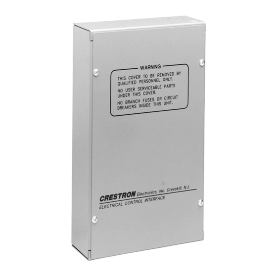
Crestron CNECI-4A Physical Description The CNECI-4A is housed in a gray, metal enclosure with silk-screened labels on the front cover. All connections are made to the internal PCB through enclosure conduit knock-outs that are located on the top, left-side, and bottom of the enclosure. Also supplied is one 4-position terminal block and one 9-position terminal block. -
Page 7: Leading Specifications
Leading Specifications The table on the next page provides a summary of leading specifications for the CNECI-4A. Dimensions and weight are rounded to the nearest hundredth unit. Electrical Control Interface with AC: CNECI-4A • 3 Operations Guide - DOC. 8149... -
Page 8: Setup
VisionTools Pro is required only for SmarTouch programming. Otherwise, it is not needed. As of the date of manufacture, the CNECI-4A has been tested and found to comply with specifications for CE marking. NOTE: This device complies with part 15 of the FCC rules. Operation is subject to... -
Page 9: Hookup
NOTE: Instead of installing discrete AC wiring for each relay, the AC line voltage may be daisy-chained from the L terminal of the AC power terminal block to the relay COM terminals. Electrical Control Interface with AC: CNECI-4A • 5 Operations Guide - DOC. 8149... - Page 10 Refer to the diagram below and complete the steps on the next page to hookup the CNECI-4A: CNECI-4A Hookup Diagram TO AC POWERED DEVICES FROM 110-125VAC or 220-250VAC CRESTRON MODEL: CNECI-4A LOCAL INPUTS CODE FROM CRESNET LOCAL SYSTEM INPUTS 6 • Electrical Control Interface with AC: CNECI-4A Operations Guide - DOC. 8149...
-
Page 11: Identity Code
03 to FE. The ID CODE of the unit must match an NET ID specified in the SIMPL Windows program. The ID CODE of the CNECI-4A is factory set to 7F. The ID CODE of the CNECI-4A can be changed by using two miniature rotary switches labeled H and L. -
Page 12: Simpl Windows Programming
NOTE: VisionTools Pro (VT Pro) is a Windows compatible software package for creating Crestron touchpanel screen designs. The basic CNECI-4A SIMPL program is shown as a block diagram on the next page. A CT-3000 touchpanel created with VT Pro, is used to control the relays of the CNECI-4A. - Page 13 Crestron CNECI-4A Electrical Control Interface with AC CNECI-4A SIMPL Program Electrical Control Interface with AC: CNECI-4A • 9 Operations Guide - DOC. 8149...
-
Page 14: How To Create The Program
CT-3000 symbol into System Views and set the NET ID to 03. Drag and drop the CNECI-4A (from Network Control Modules folder in the Device Library) into System Views. The NET ID of the CNECI-4A is set to 7F. NOTE: SIMPL Windows v1.30.01 or later is required to program the control system containing a CNECI-4A. - Page 15 CT-3000 and CNECI-4A symbols were added automatically when the devices were added to the system in the Configuration Manager workspace. Expand the Network Modules folder and double click on the CT-3000 and CNECI-4A for detail views (alternatively CTRL+D or drag and drop into Detail View). Assign the signals as shown after this paragraph.
- Page 16 Detail View of a AND (S-6) in SIMPL Windows’ Programming Manager Detail View of a BUFFER (S-7) in SIMPL Windows’ Programming Manager Detail View of a AND (S-8) in SIMPL Windows’ Programming Manager 12 • Electrical Control Interface with AC: CNECI-4A Operations Guide - DOC. 8149...
-
Page 17: Problem Solving
For assistance in your local time zone, refer to the Crestron website (www.crestron.com) for a listing of Crestron worldwide offices. You can also log onto the online help section of the Crestron website (www.crestron.com) to ask questions about Crestron products. First-time users will need to establish a user account to fully benefit from all available features. -
Page 18: Return And Warranty Policies
CRESTRON shall not be liable to honor the terms of this warranty if the product has been used in any application other than that for which it was intended, or if it has been subjected to misuse, accidental damage, modification, or improper installation procedures. - Page 19 Crestron CNECI-4A Electrical Control Interface with AC This page intentionally left blank. Electrical Control Interface with AC: CNECI-4A • 15 Operations Guide - DOC. 8149...
- Page 20 Crestron Electronics, Inc. Operations Guide – DOC. 8149 15 Volvo Drive Rockleigh, NJ 07647 07.99 Tel: 888.CRESTRON Fax: 201.767.7576 Specifications subject to www.crestron.com change without notice.
Need help?
Do you have a question about the CNECI-4A and is the answer not in the manual?
Questions and answers