Table of Contents
Advertisement
Quick Links
Download this manual
See also:
User Manual
Advertisement
Chapters
Table of Contents

Subscribe to Our Youtube Channel
Related Manuals for IBASE Technology MI808


Summary of Contents for IBASE Technology MI808
- Page 1 MI808 Mini-ITX Motherboard USER’S MANUAL Version 1.1...
- Page 2 PS/2 is a trademark of International Business Machines Corporation. Microsoft Windows is a registered trademark of Microsoft Corporation. Winbond is a registered trademark of Winbond Electronics Corporation. All other product names or trademarks are properties of their respective owners. MI808 User’s Manual...
-
Page 3: Table Of Contents
Table of Contents Introduction ............1 Product Description............. 1 Checklist................2 MI808 Specifications ............3 Board Dimensions ............... 6 Installations ............7 Installing the Memory ............8 Setting the Jumpers ............. 9 Connectors on MI808............16 BIOS Setup ............32 Drivers Installation ........48 Intel Chipset Software Installation Utility...... - Page 4 This page is intentionally left blank. MI808 User’s Manual...
-
Page 5: Introduction
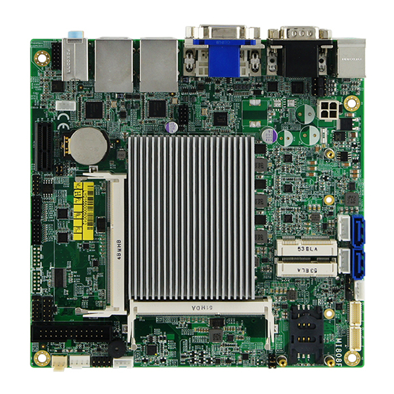
INTRODUCTION Introduction Product Description MI808 is a Mini ITX board (170mm x 170mm) that comes with the Intel Intel® Pentium ® N3000 series processor. It has two DDR3L SO-DIMM sockets supporting up to 8GB of system memory. It also features the Intel® Gen8-LP graphics engine with interface for CRT, DVI-D and 24-bit dual channel LVDS displays. -
Page 6: Checklist
INTRODUCTION Checklist Your MI808 package should include the items listed below. • The MI808 Mini-ITX motherboard • This User’s Manual • 1 CD containing chipset drivers and flash memory utility • Serial ATA cable • I/O shield MI808 User’s Manual... -
Page 7: Mi808 Specifications
4-in / 4-out (User configurable) Digital IO PCIe (1x) slot x 1 Expansion Slots Full-sized Mini-PCIe x 2 [Mounting holes for full-sized (x2) + half-sized (x1)] Mini-PCIe #1 supports PCIe(1x) / USB signal Mini-PCIe #2 supports mSATA / USB signal MI808 User’s Manual... - Page 8 INTRODUCTION CFast x 1 @ solder side [Except MI808FW-370A] MI808 User’s Manual...
- Page 9 Window Embedded 8 Windows 7 (64-bit) Linux (Fedora, uBuntu) RoHS CE /FCC/LVD Certification Operation Temperature: 0~60 degree C Environment Storage Temperature: -40 ~ 80 degree C Relative humidity: 90%, non-condensing @ 60 degree C 170mm x 170mm Board Size MI808 User’s Manual...
-
Page 10: Board Dimensions
INTRODUCTION Board Dimensions MI808 User’s Manual... -
Page 11: Installations
INSTALLATIONS Installations This section provides information on how to use the jumpers and connectors on the MI808 in order to set up a workable system. The topics covered are: Installing the Memory ................8 Setting the Jumpers................9 Connectors on MI808 ................16... -
Page 12: Installing The Memory
Installing the Memory The MI808 board supports two DDR3L-1600 memory slots. Remarks: MI808 supports two SO-DIMM (w/o ECC) modules. Total maximum memory supported is 8GB. Installing and Removing Memory Modules To install the DDR3L modules, locate the memory slot on the board and perform the following steps: 1. -
Page 13: Setting The Jumpers
INSTALLATIONS Setting the Jumpers Jumpers are used on MI808 to select various settings and features according to your needs and applications. Contact your supplier if you have doubts about the best configuration for your needs. The following lists the connectors on MI808 and their respective functions. -
Page 14: Jumper Locations On Mi808
INSTALLATIONS Jumper Locations on MI808 Jumpers on MI808 ................Page JP1: LCD Backlight Connector ............11 JP2: LVDS Panel Brightness Control Selection ........11 JP3/JP4 COM1/COM2 RS232 RI/+5V/+12V Power Setting....12 JP8: Clear CMOS Contents ..............13 JP7: Clear ME Contents............... 14 JP9: For SPI Debug Tools .............. -
Page 15: Jp1: Lcd Backlight Connector
INSTALLATIONS JP1: LCD Backlight Connector Pin # Signal Name +12V Backlight Enable Brightness Control Ground JP2: LVDS Panel Brightness Control Selection Brightness Control Setting (PWM mode) Open 3.3V Close 5V(Default) MI808 User’s Manual... -
Page 16: Jp3/Jp4 Com1/Com2 Rs232 Ri/+5V/+12V Power Setting
INSTALLATIONS JP3/JP4 COM1/COM2 RS232 RI/+5V/+12V Power Setting JP3/JP4 Setting Function Pin 1-3 +12V Short/Closed Pin 3-4 Short/Closed Pin 3-5 Short/Closed MI808 User’s Manual... -
Page 17: Jp8: Clear Cmos Contents
INSTALLATIONS JP8: Clear CMOS Contents Setting Function Pin 1-2 Normal Short/Closed Pin 2-3 Clear CMOS Short/Closed MI808 User’s Manual... -
Page 18: Jp7: Clear Me Contents
INSTALLATIONS JP7: Clear ME Contents Setting Function Pin 1-2 Normal Short/Closed Pin 2-3 Clear ME Short/Closed REGISTER JP9: For SPI Debug Tools MI808 User’s Manual... -
Page 19: J22: Atx/At Mode
INSTALLATIONS J22: ATX/AT Mode Setting Function Open ATX (Default) Close MI808 User’s Manual... -
Page 20: Connectors On Mi808
INSTALLATIONS Connectors on MI808 Connector Locations on MI808 ............17 CN1 / CN2: SATA3 Connectors ............18 CN2 Share with CN9 ................18 CN3: PS2 Keyboard/Mouse..............18 CN4: COM1 / COM2 ................18 CN5: CRT+DVI Connector ..............19 CN6/CN7: Gigabit LAN / USB 3.0 Connector ........19 CN8: Audio Connector ................ -
Page 21: Connector Locations On Mi808
INSTALLATIONS Connector Locations on MI808 Connector Locations on MI808 MI808 User’s Manual... -
Page 22: Cn1 / Cn2: Sata3 Connectors
INSTALLATIONS CN1 / CN2: SATA3 Connectors CN2 Share with CN9 (CFAST) CN3: PS2 Keyboard/Mouse CN4: COM1 / COM2 Pin # Signal Name RS-232 R2-422 RS-485 DATA- DATA+ Ground Ground Ground MI808 User’s Manual... -
Page 23: Cn5: Crt+Dvi Connector
Signal Name Pin # Pin # Signal Name DATA2- DATA2+ N.C. N.C. DDCCLK DDCDATA N.C. DATA1- DATA1+ N.C. N.C. Hot Plug Detect DATA0- DATA0+ N.C. N.C. CLK+ CLK- CN6/CN7: Gigabit LAN / USB 3.0 Connector CN8: Audio Connector MI808 User’s Manual... -
Page 24: Cn9: Cfast Connector
INSTALLATIONS CN9: CFAST Connector J1, J2: LVDS Connectors, Hirose DF20G-20DP-1V MI808 User’s Manual... -
Page 25: J2: First Channel Lvds
Signal Name TX0N TX0P Ground Ground TX1N TX1P Ground Ground TX2N TX2P Ground Ground CLKN CLKP Ground Ground TX3N TX3P Power Power J3: LVDS Panel Power Selection Setting Panel Voltage Pin 1-2 3.3V (default) Short/Closed Pin 2-3 Short/Closed MI808 User’s Manual... -
Page 26: J4 / J5: Sata Hdd Power Connectors
INSTALLATIONS J4 / J5: SATA HDD Power Connectors Pin # Signal Name Ground Ground +12V J6: DC_IN Connector Pin # Signal Name Ground Ground +12V or +24V +12V or +24V MI808 User’s Manual... -
Page 27: J8 / J9: Mini Pcie Slot (Sim Card)
INSTALLATIONS J8 / J9: Mini PCIE Slot (SIM Card J7) J8 mSATA only (Share with CN1, W/O USB) F_USB1: USB 2.0 Signal Name Pin # Pin # Signal Name Ground Ground MI808 User’s Manual... -
Page 28: J10: Ddr3L So-Dimm (Ch-A) Sockets
INSTALLATIONS J10: DDR3L SO-DIMM (CH-A) Sockets J13: DDR3L SO-DIMM (CH-B) Sockets MI808 User’s Manual... -
Page 29: J11: Mcu Jtag
INSTALLATIONS J11: MCU JTAG J12: Front Panel Signal Name Pin # Pin # Signal Name PWR_BTN 3.3V HDD Active Reset MI808 User’s Manual... -
Page 30: J15 Amplifier Connector
INSTALLATIONS J15 Amplifier Connector Pin # Signal Name OUTL+ OUTL- OUTR- OUTR+ MI808 User’s Manual... -
Page 31: J16 Audio Connector (Df11-12Dp-2Dsa)
INSTALLATIONS J16 Audio Connector (DF11-12DP-2DSA) Signal Name Pin # Pin # Signal Name LINEOUT_R LINEOUT_L Ground JD_FRONT LINEIN_R LINEIN_L Ground JD_LINEIN MIC-R MIC_L Ground JD_MIC1 MI808 User’s Manual... -
Page 32: J17: Digital I/O
INSTALLATIONS J17: Digital I/O Signal Name Pin # Pin # Signal Name OUT3 OUT1 OUT2 OUT0 MI808 User’s Manual... -
Page 33: J18, J19: Com3/Com4
INSTALLATIONS J18, J19: COM3/COM4 Signal Name Pin # Pin # Signal Name Data carrier detect Receive data Transmit data Data terminal ready Ground Data set ready Request to send Clear to send Ring indicator Not Used MI808 User’s Manual... -
Page 34: Cpu_Fan1: Cpu Fan Power Connector
INSTALLATIONS CPU_FAN1: CPU Fan Power Connector Pin # Signal Name Ground +12V Rotation detection Control SYS_FAN1: System Fan1 Power Connector MI808 User’s Manual... -
Page 35: J7: Sim Card Slot
INSTALLATIONS J7: SIM Card Slot JP5/JP6: Reserved J14: LPT Port Connector MI808 User’s Manual... -
Page 36: Bios Setup
BIOS that comes with the board. The topics covered in this chapter are as follows: BIOS Introduction ................33 BIOS Setup ..................33 Advanced Settings ................34 CSM Configuration ................41 Chipset Settings ................... 43 Security Settings .................. 45 Boot Settings..................46 Save & Exit Settings ................47 MI808 User’s Manual... -
Page 37: Bios Introduction
These defaults have been carefully chosen by both AMI and your system manufacturer to provide the absolute maximum performance and reliability. Changing the defaults could cause the system to become unstable and crash in some cases. MI808 User’s Manual... -
Page 38: System Date
► F81866/F81846 H/W Monitor Enter: Select ► CPU Configuration Change Opt F1: General Help ► SATA Configuration ► Network Stack Configuration F2: Previous Values F3: Optimized Default ► CSM Configuration F4: Save & EXIT ► USB Configuration ESC: Exit MI808 User’s Manual... - Page 39 TPM 1.2 will restrict support to TPM 1.2 devices, TPM 2.0 will restrict support to TPM 2.0 devices, Auto will support both with the default set to TPM 2.0 devices if not found, TPM 1.2 devices will be enumerated. MI808 User’s Manual...
-
Page 40: Acpi Settings
LVDS (eDP/DP) Configuration → ← Select Screen LVDS (eDP/DP) Support Disabled ↑↓ Select Item Enter: Select Change Field F1: General Help F2: Previous Values F3: Optimized Default F4: Save ESC: Exit LVDS (eDP/DP) Support LVDS (eDP/DP) ON/OFF MI808 User’s Manual... - Page 41 This field sets the system power status whether Disable or Enable when power returns to the system from a power failure situation. Temperature Guardian Generate the reset signal when system hangs up on POST. Schedule Slot 1 / 2 Setup the hour/minute for system power on. MI808 User’s Manual...
-
Page 42: Serial Port Configuration
F4: Save V1.35 +1.352 V ESC: Exit Temperatures/Voltages These fields are the parameters of the hardware monitoring function feature of the board. The values are read-only values as monitored by the system and show the PC health status. MI808 User’s Manual... -
Page 43: Cpu Configuration
Microcode Patch Change Field Max CPU Speed 1600 MHz F1: General Help Min CPU Speed 480 MHz F2: Previous Values Processor Cores F3: Optimized Default Intel HT Technology Not Supported F4: Save Intel VT-x Technology Supported ESC: Exit MI808 User’s Manual... -
Page 44: Sata Configuration
Enable / Disable SATA Device SATA Mode Selection Determines how SATA controller operate. SATA Interface Speed Select SATA Interface Speed CHV A1 always with Gen1 Speed. Port Enable or Disable SATA Port Hot Plug Designates this port as Hot Pluggable. MI808 User’s Manual... -
Page 45: Network Stack Configuration
Controls the execution of UEFI and Legacy PXE OpROM Storage Controls the execution of UEFI and Legacy Storage OpROM Video Controls the execution of UEFI and Legacy Video OpROM Other PCI device Determines OpROM execution policy for devices other than Network, Storage, or Video. MI808 User’s Manual... - Page 46 Maximum time the device will take before it properly reports itself to the Host Controller. ‘Auto’ uses default value: for a Root port it is 100ms, for a Hub port the delay is taken from Hub descriptor. MI808 User’s Manual...
-
Page 47: Chipset Settings
Aptio Setup Utility Chipset Main Advanced Boot Security Save & Exit ► Azalia Configuration ► USB Configuration ► PCI Express Configuration Azalia Configuration Azalia HD Audio Options USB Configuration USB Configuration Settings PCI Express Configuration PCI Express Configuration Settings MI808 User’s Manual... -
Page 48: Xhci Mode
► PCI Express Root Port 2 F1: General Help ► PCI Express Root Port 3 F2: Previous Values ► PCI Express Root Port 4 F3: Optimized Default F4: Save ESC: Exit PCI Express Configuration PCI Express Root Port Settings. MI808 User’s Manual... -
Page 49: Security Settings
Enter: Select Minimum length Change Field F1: General Help Maximum length F2: Previous Values F3: Optimized Default Administrator Password User Password F4: Save ESC: Exit Administrator Password Set Setup Administrator Password. User Password Set User Password. MI808 User’s Manual... -
Page 50: Boot Settings
Bootup NumLock State Select the keyboard NumLock state. Quiet Boot Enables/Disables Quiet Boot option. Fast Boot Enables/Disables boot with initialization of a minimal set of devices required to launch active boot option. Has no effect for BBS boot options. MI808 User’s Manual... -
Page 51: Save & Exit Settings
Discard Changes done so far to any of the setup options. Restore Defaults Restore/Load Defaults values for all the setup options. Save as User Defaults Save the changes done so far as User Defaults. Restore User Defaults Restore the User Defaults to all the setup options. MI808 User’s Manual... -
Page 52: Drivers Installation
Realtek HD Audio Driver Installation ..........54 LAN Drivers Installation ..............55 TXE Drivers Installation..............58 IMPORTANT NOTE: After installing your Windows operating system, you must install first the Intel Chipset Software Installation Utility before proceeding with the drivers installation. MI808 User’s Manual... -
Page 53: Intel Chipset Software Installation Utility
Plug & Play INF support for Intel chipset components. Follow the instructions below to complete the installation. 1. Insert the disc that comes with the board. Click Intel and then Intel(R) Braswell Chipset Drivers. 2. Click Intel(R) Chipset Software Installation Utility MI808 User’s Manual... - Page 54 DRIVERS INSTALLATION 3. When the Welcome screen to the Intel® Chipset Device Software appears, click Next to continue. MI808 User’s Manual...
- Page 55 4. Click Accept to accept the software license agreement and proceed with the installation process. 5. On the Readme File Information screen, click Install to continue the installation. 6. The Setup process is now complete. Click Finish to restart the computer and for changes to take effect. MI808 User’s Manual...
-
Page 56: Vga Drivers Installation
DRIVERS INSTALLATION VGA Drivers Installation 1. Click Intel(R) Braswell Graphics Driver 2. When the Welcome screen appears, click Next to continue. 3. Click Yes to to agree with the license agreement and continue the installation. MI808 User’s Manual... - Page 57 4. On the Readme File Information screen, click Next to continue the installation of the Intel® Graphics Driver. 5. On Setup Progress screen, click Next to continue. 6. Setup complete. Click Finish to restart the computer and for changes to take effect. MI808 User’s Manual...
-
Page 58: Realtek Hd Audio Driver Installation
Realtek HD Audio Driver Installation 1. Click Realtek High Definition Audio Driver. 2. On the Welcome to the InstallShield Wizard screen, click Next to proceed with and complete the installation process. 3. Restart the computer when prompted. MI808 User’s Manual... -
Page 59: Lan Drivers Installation
DRIVERS INSTALLATION LAN Drivers Installation 1. Insert the CD that comes with the board. Click LAN Card and then Intel LAN Controller Drivers. 2. Click Intel(R) I21x Gigabit Network Drivers 3. In the Welcome screen, click Next. MI808 User’s Manual... - Page 60 4. In the License Agreement screen, click I accept the terms in license agreement and Next to accept the software license agreement and proceed with the installation process. 5. Click the checkbox for Drivers in the Setup Options screen to select it and click Next to continue. MI808 User’s Manual...
- Page 61 DRIVERS INSTALLATION 6. When the Ready to Install the Program screen appears, click Install to continue. 7. When InstallShield Wizard is complete, click Finish. MI808 User’s Manual...
-
Page 62: Txe Drivers Installation
DRIVERS INSTALLATION TXE Drivers Installation 1. Click Intel(R) TXE Driver 2. When the Welcome screen appears, click Next to continue. MI808 User’s Manual... - Page 63 3. Click Next to to agree with the license agreement and continue the installation. 4. On the Confirmation screen, click Next to continue the installation of the Intel(R) TXE Driver. 5. Setup complete. Click Finish to restart the computer and for changes to take effect. MI808 User’s Manual...
-
Page 64: Appendix
378h – 37Fh Printer Port (LPT1) 3B0h – 3BBh Intel(R) HD Graphics 3E8h – 3EFh Communications Port (COM3) 3F8h – 3FFh Communications Port (COM1) 040h – 05Fh Intel(R) Celeron(R)/Pentium(R) SM Bus Controller 060h – 07Fh Standard SATA AHCI Controller MI808 User’s Manual... -
Page 65: Interrupt Request Lines (Irq)
System timer IRQ1 Standard PS/2 Keyboard IRQ3 Communications Port (COM2) IRQ4 Communications Port (COM1) IRQ6 Communications Port (COM3) IRQ10 Communications Port (COM4) IRQ11 PS/2 Compatible Mouse IRQ12 Intel(R) Celeron(R)/Pentium(R) SM Bus Controller IRQ19 Standard SATA AHCI Controller MI808 User’s Manual... -
Page 66: Watchdog Timer Configuration
(argc != 2) printf(" Parameter incorrect!!\n"); return (1); bTime = strtol (argv[1], endptr, 10); printf("System will reset after %d seconds\n", bTime); if (bTime) EnableWDT(bTime); } else DisableWDT(); return 0; //--------------------------------------------------------------------------- void EnableWDT(int interval) unsigned char bBuf; MI808 User’s Manual... - Page 67 //--------------------------------------------------------------------------- void DisableWDT(void) unsigned char bBuf; Set_F81866_LD(0x07); //switch to logic device 7 bBuf = Get_F81866_Reg(0xFA); bBuf &= ~0x01; Set_F81866_Reg(0xFA, bBuf); //disable WDTO output bBuf = Get_F81866_Reg(0xF5); bBuf &= ~0x20; bBuf |= 0x40; Set_F81866_Reg(0xF5, bBuf); //disable WDT //--------------------------------------------------------------------------- MI808 User’s Manual...
- Page 68 F81866_REG_LD); outportb(F81866_DATA_PORT, LD); Lock_F81866(); //--------------------------------------------------------------------------- void Set_F81866_Reg( unsigned char REG, unsigned char DATA) Unlock_F81866(); outportb(F81866_INDEX_PORT, REG); outportb(F81866_DATA_PORT, DATA); Lock_F81866(); //--------------------------------------------------------------------------- unsigned char Get_F81866_Reg(unsigned char REG) unsigned char Result; Unlock_F81866(); outportb(F81866_INDEX_PORT, REG); Result = inportb(F81866_DATA_PORT); Lock_F81866(); return Result; MI808 User’s Manual...
- Page 69 (F81866_BASE) #define F81866_DATA_PORT (F81866_BASE+1) //--------------------------------------------------------------------------- #define F81866_REG_LD 0x07 //--------------------------------------------------------------------------- #define F81866_UNLOCK 0x87 #define F81866_LOCK 0xAA //--------------------------------------------------------------------------- unsigned int Init_F81866(void); void Set_F81866_LD( unsigned char); void Set_F81866_Reg( unsigned char, unsigned char); unsigned char Get_F81866_Reg( unsigned char); //--------------------------------------------------------------------------- #endif //__F81866_H MI808 User’s Manual...
- Page 70 Fintek 81865/81866, program abort.\n"); return(1); }//if (SIO == 0) Dio5Initial(); //for GPIO50..57 Dio5SetDirection(0xF0); //GP50..53 = input, GP54..57=output printf("Current DIO direction = 0x%X\n", Dio5GetDirection()); printf("Current DIO status = 0x%X\n", Dio5GetInput()); printf("Set DIO output to high\n"); MI808 User’s Manual...
- Page 71 = Get_F81865_Reg(0x2A); ucBuf &= ~BIT3;//clear bit 3, ucBuf |= BIT1;//set bit 1, Set_F81865_Reg(0x2a, ucBuf); //GPIO51 ~ GPIO52 //clear UR6_ALT_EN(bit5), IR_ALT_EN(bit4),set FDC_GP_EN(bit3) //GPIO50 //set FDC_GP_EN(bit3), clear RTS6_ALT_EN(RTS6_2_ALT_EN)(bit6) ucBuf = Get_F81865_Reg(0x2A); ucBuf &= ~(BIT4+BIT5+BIT6); //clear UR6_ALT_EN(bit5), IR_ALT_EN(bit4), RTS6_ALT_EN(RTS6_2_ALT_EN)(bit6) Set_F81865_Reg(0x2a, ucBuf); MI808 User’s Manual...
- Page 72 Dio5SetDirection(unsigned char NewData) //NewData : 1 for input, 0 for output Set_F81865_LD(0x06); //switch to logic device 6 Set_F81865_Reg(0xA0, NewData); //--------------------------------------------------------------------------- unsigned char Dio5GetDirection(void) unsigned char result; Set_F81865_LD(0x06); //switch to logic device 6 result = Get_F81865_Reg(0xA0); return (result); //--------------------------------------------------------------------------- MI808 User’s Manual...
Need help?
Do you have a question about the MI808 and is the answer not in the manual?
Questions and answers