Sign In
Upload
Download
Table of Contents
Contents
Add to my manuals
Delete from my manuals
Share
URL of this page:
HTML Link:
Bookmark this page
Add
Manual will be automatically added to "My Manuals"
Print this page
×
Bookmark added
×
Added to my manuals
Manuals
Brands
Danfoss Manuals
Touch terminals
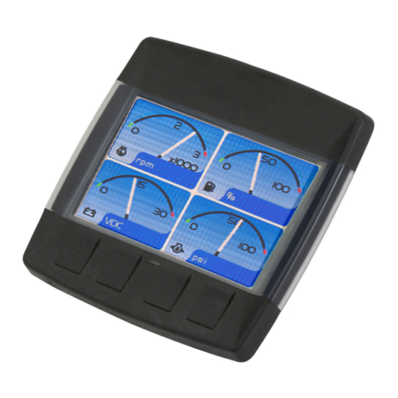
DP200
User manual
Danfoss DP200 User Manual
Dp2 series eic engine information center
Hide thumbs
1
2
3
4
5
6
7
8
9
10
11
12
13
14
15
16
17
18
19
20
21
22
23
24
25
26
27
28
29
30
31
32
33
34
35
36
37
38
39
40
41
42
43
44
45
46
47
48
Table Of Contents
49
page
of
49
Go
/
49
Contents
Table of Contents
Bookmarks
Table of Contents
Table of Contents
EIC-Engine Information Center – Dp2Xx
Before You Start
The Engine Information Center (EIC)
Brightness/Contrast Adjustment
Navigation Using Soft Keys
Navigate down
Navigate up
Brightness/Contrast
Screen Navigation
EIC Dp2Xx Force and Inhibit Regeneration Software Function Description
Force Regeneration Action
Inhibit Regeneration Action
Start Menu
Main Menu
Basic Setup
Overview
Language
Time/Date
Units
Unit Selection Options
Diagnostics
System Info
Fault Log
Fault Log: Active and Previous Faults
Fault Pop-Up Alarms
Fault Pop-Up Soft Key Actions
Device List
Quick Data
Screen Setup
Parameters
Number of Screens
Select Screen
Display Setting
PIN Protection
Change PIN Code
Trip Reset
Selecting Screen Number and Types
Setup Options
Screen Variants
Screen Type 1
Screen Type 2
Screen Type 3
Selecting J1939 Monitor Signals
J1939 Monitor Controls
Signal Monitor Functions
High Exhaust System Temperature Lamp
Lamps
Particulate Filter Lamp
LED Indicators
Panel Bracket Assembly
Mounting and Fastening Installation
Installation/Mounting Instructions
Surface Mount
Panel Gasket Dimensions
Real Time Clock/ Low Temperature Functionality
Inputs/Outputs
Model Name
DP200 Series Model Code Variants
DP211 Series Model Code Variants
DP250 Series Model Code Variants
DP200 Series- Deutsch Connector
DP200 Series Pin Assignments
Connection/Pinout Settings
DP250 Series- Deutsch Connector
DP250 Series Pin Assignments
Connection Tools
Related Parts & Kits
Electrical Connection Kits
DP200 Series Related Products Part Numbers
Dp2Xx Series Accessories
DP200 Mounting Kit
DP211 Mounting Kit
DP250 Mounting Kit
Software
Important Safety Information
Advertisement
Quick Links
1
Before You Start
2
The Engine Information Center (Eic)
3
Navigation Using Soft Keys
4
Main Menu
5
Setup Options
6
J1939 Monitor Controls
7
Led Indicators
8
Connection/Pinout Settings
Download this manual
User Manual
DP2xx series – EIC Engine Information Center
powersolutions.danfoss.com
Table of
Contents
Previous
Page
Next
Page
1
2
3
4
5
Advertisement
Table of Contents
Need help?
Do you have a question about the DP200 and is the answer not in the manual?
Ask a question
Questions and answers
Subscribe to Our Youtube Channel
Related Manuals for Danfoss DP200
Touch terminals Danfoss DP250 User Manual
Dp2 series eic engine information center (49 pages)
This manual is also suitable for:
Dp211
Dp250
Table of Contents
Save PDF
Print
Rename the bookmark
Delete bookmark?
Delete from my manuals?
Login
Sign In
OR
Sign in with Facebook
Sign in with Google
Upload manual
Upload from disk
Upload from URL


Need help?
Do you have a question about the DP200 and is the answer not in the manual?
Questions and answers