Table of Contents
Advertisement
Quick Links
Advertisement
Table of Contents

Related Manuals for Rae PGM62x6


Summary of Contents for Rae PGM62x6
- Page 1 MultiRAE Series User’s Guide Rev J September 2017 P/N: M01-4003-000...
-
Page 2: Product Registration
Register your product online by visiting: http://www.raesystems.com/support/product-registration By registering your product, you can: Receive notification of product upgrades or enhancements Be alerted to Training classes in your area Take advantage of RAE Systems special offers and promotions... -
Page 3: Table Of Contents
Contents Features Comparison ......................10 Standard Contents ......................11 General Information ......................12 Key Features ......................13 User Interface ........................15 Display Overview .......................15 4.1.1 Mesh Radio Status Indicator Icons ...............15 4.1.1.1 Wi-Fi Status Indicator Icons ................17 4.1.2 Keys And Interface ....................18 4.1.3 LCD Flip .......................18 4.1.4 Key Remapping When LCD Is Flipped ..............19 Screen Display For Various Numbers Of Active Sensors ...........20... - Page 4 Enter Programming In Advanced Mode ..............49 Enter Programming In Basic Mode ................50 Menus And Submenus ....................51 9.3.1 Editing And Selecting Parameters And Sensors ..........51 9.3.2 Calibration ......................52 9.3.3 Bias & Equilibration For Liquid O And Other Biased Sensors ......52 9.3.3.1 Fresh Air .......................52 9.3.3.2 Multi Sensor Span ..................54...
- Page 5 9.3.11.5 Fast Startup ....................81 9.3.11.6 Temperature Units ..................81 9.3.11.7 Language ......................81 9.3.11.8 Site ID ......................81 9.3.11.9 User ID ......................81 9.3.11.10 Date Format ....................81 9.3.11.11 Date ......................82 9.3.11.12 Time Format ....................82 9.3.11.13 Time ......................82 9.3.11.14 User Mode ....................82 9.3.11.15 Backlight ......................82 9.3.11.16 LCD Flip ......................82 Policy Enforcement ......................83 10.1...
- Page 6 14.6 Replacing The Pump ....................109 Alarms Overview ......................110 15.1 Alarm Signals ......................110 15.2 Changing The Alarm Mode ..................110 15.3 Alarm Signal Summary .................... 111 15.3.1 Hygiene Mode ....................111 15.3.2 Search Mode ..................... 112 15.3.3 General Alarms ....................113 Troubleshooting ......................
- Page 7 WARNINGS Read Before Operating This manual must be carefully read by all individuals who have or will have the responsibility of using, maintaining, or servicing this product. The product will perform as designed only if it is used, maintained, and serviced in accordance with the manufacturer’s instructions. CAUTION! Never operate the monitor when the cover is removed.
- Page 8 SPECIAL CONDITIONS FOR SAFE USE The PGM-62xx shall only be fitted with RAE Systems Battery Pack type M01-3051-000, M01-3053-000, M01-3055-000, or M01-3056-000 or Battery Adapter M01-3052-000 or M01-3054-000 fitted with Duracell MN1500 batteries. The PGM62xx shall only be charged outside hazardous areas.
-
Page 9: Fcc Part 15 Statement
Hazardous Areas classified by Zones PGM62x0/PGM62x6 are intended to be used in hazardous areas zone 0, zone 1 or zone 2, and PGM62x8 in hazardous areas zone 1 or zone 2 within the temperature range of -20º C to +50º C, where gases of explosion groups IIA, IIB or IIC and T4 may be present. -
Page 10: Features Comparison
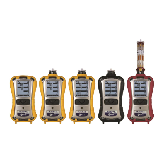
Features Comparison This chart shows the differences between the various MultiRAE models. (For information on the MultiRAE MX, refer to the MultiRAE MX data sheet and User’s Guide.) MultiRAE MultiRAE MultiRAE Lite MultiRAE Benzene Appearance Gamma Radiation Sensor ppb PID (10.6 eV;... -
Page 11: Standard Contents
Calibration adapter 6" flexible probe 3 spare external filters 10 charcoal filters (reduce CO sensor’s cross-sensitivity to VOCs) RAE-Sep Tube Cartridges PID sensor cap removal tool PID zeroing charcoal filter Toolkit QuickStart Guide CD with documentation CD with ProRAE Studio II... -
Page 12: General Information
General Information The MultiRAE is a family of multi-threat gas detectors that combine continuous monitoring capabilities for volatile organic compounds (VOCs), toxic and combustible gases, and radiation, with Man Down Alarm functionality in one highly portable instrument. MultiRAE monitors offer an industry-leading selection of interchangeable field-replaceable electrochemical, combustible, infrared, PID (photoionization detector), and gamma radiation sensors to fit a wide variety of applications. -
Page 13: Key Features
3.1 Key Features All-in-one continuous monitoring capabilities for gamma radiation, VOCs, oxygen, toxic and combustible gases, for a total of up to six threats at a time Highly customizable with over 25 field-interchangeable intelligent sensor options Wireless access to real-time instrument readings and alarm status from any location through ProRAE Guardian Real-Time Wireless Safety System ... - Page 14 MultiRAE Lite Diffusion Model, MultiRAE Benzene with rear view RAE-Sep Tube Cartridge Gas inlets Alarm Alarm LEDs Buzzer Note: The front of the diffusion model of the MultiRAE Lite is the same as the pumped model, but instead of a single...
-
Page 15: User Interface
User Interface The MultiRAE’s user interface consists of the display, alarm LEDs, an alarm buzzer, and three keys. 4.1 Display Overview The LCD display provides visual feedback that includes the sensor types, readings, alarm status, battery condition, and other information. “All sensors tested and calibrated according to policy”... - Page 16 Icon Function Roaming status: Network joined, received signal strength medium (41% to 60%) Roaming status: Network joined, received signal strength good (61% to 80%) Roaming status: Network joined, received signal strength very good (81% to 100%) Pump status (only on pump-equipped models) Datalogging status (shown when datalogging is on, blank when off) Battery status (three segments show battery charge level) Man Down alarm enabled...
-
Page 17: Wi-Fi Status Indicator Icons
4.1.1.1 Wi-Fi Status Indicator Icons Wi-Fi has its own set of icons, which includes messaging icons. Icon Description Notes If the instrument’s Wi-Fi is Wi-Fi is connected to the wireless access point not associated with the access point, blinks at 1- second intervals Wi-Fi received signal strength 0% to 20%... -
Page 18: Keys And Interface
4.1.2 Keys And Interface The MultiRAE has three keys: MODE In addition to their labeled functions, [Y/+], [MODE], and [N/-] act as “soft keys” that control different parameters and make different selections within the instrument’s menus. From menu to menu, each key controls a different parameter or makes a different selection. -
Page 19: Key Remapping When Lcd Is Flipped
4.1.4 Key Remapping When LCD Is Flipped When the instrument is inverted and the LCD flips, the keys are remapped to the functions shown on the screen. Display with MultiRAE in non-inverted position: Display with MultiRAE inverted:... -
Page 20: Screen Display For Various Numbers Of Active Sensors
4.2 Screen Display For Various Numbers Of Active Sensors The MultiRAE family of instruments can display readings from one to six sensors (including dual sensors), depending on the configuration. In order to maximize readability and the amount of information shown, the display is automatically reconfigured, according to the number and types of sensors in the MultiRAE. -
Page 21: Menus
4.3 Menus The reading menus are easy to step through by pressing the [N/-] key. Hygiene Mode: Sampling is continuous, and Hygiene Mode allows you to clear peak and minimum values at any time. Search Mode: Samples only when you tell it to sample. This allows you to save sample readings as individual events in the datalog. -
Page 22: Search Mode
4.3.2 Search Mode Notes: If the instrument is not equipped with a VOC sensor (PID), or is not equipped with an LEL sensor, then screens for those sensors (VOC Gas Status and LEL Gas Status, respectively) are not shown. ... - Page 23 MultiRAE Benzene (TVOC and Benzene Modes) Notes: When prompted to start benzene sampling, there is an option to view a tutorial. This is helpful if you do not have this User’s Guide in the field or if you are unfamiliar with how to ready the MultiRAE Benzene for benzene sampling.
-
Page 24: Wireless Control And Submenus
Wireless Control And Submenus When you step through the main menu, as shown in the previous diagrams, there are screens for wireless communication. Note: These are only present if the MultiRAE is equipped with a wireless module. At the Radio On/Off screen, you can turn the radio on or off, if the MultiRAE is in Advanced User Mode. -
Page 25: Point-To-Point Wired Connection
Point-To-Point Wired Connection The MultiRAE can communicate with other devices through P2P (point-to-point) wiring. Turning on P2P requires connecting the MultiRAE with a computer running ProRAE Studio II software and toggling P2P on. Note: When P2P is active, the wireless modem (if one is installed in the MultiRAE) is disabled. Refer to page 102 for detailed information on connecting the MultiRAE to a PC running ProRAE Studio 6.1 Using ProRAE Studio II To Set P2P Operation Important! P2P (point-to-point) operation requires a License Key. - Page 26 The main ProRAE Studio screen is shown: 7. Under “Operation,” select “License.” 8. When the License Wizard appears, click “Next.”...
- Page 27 Enter the 20-character License Key that you received from Honeywell’s Customer Support. 10. Click “Next.” The License Wizard connects to the License Manager, uploads information, and registers the License Key. When the License Key is registered, this message is shown: Note: “Count”...
- Page 28 11. Click “Finish.” Each time you open ProRAE Studio II and connect to a MultiRAE, the menu item “P2P protocol” appears in the list, and you can enable or disable the feature. Important! The MultiRAE must have firmware version 1.50 or higher installed in order to enable P2P switch functionality.
-
Page 29: Enabling P2P
6.1.2 Enabling P2P 1. With the MultiRAE connected to the PC, establish communication with ProRAE Studio. Refer to page 102 for details. 2. Click “Setup” to download the MultiRAE’s setup data. 3. Click “P2P Protocol” to open the P2P Protocol pane. 4. -
Page 30: Connecting A Multirae To A Pc To Enable Point-To-Point Operation
Note: Do not plug in both the USB and the AC adapter at the same time, as this may cause errors. Follow one of the three diagrams below for power and data connection options. Note: Refer To RAE Systems Technical Note TN-190 for more information on how point-to-point operation works. -
Page 31: Charging With The Multirae Desktop Cradle
7. Battery Always make sure the batteries are fully charged before using the MultiRAE. Three battery options are available for the MultiRAE (PGM 62x6/62x8): 1. Standard duration rechargeable Li-ion battery (PN: M01-3051-000) 2. Extended-duration rechargeable Li-ion battery delivering 50% more runtime than the standard battery (PN: M01-3056-000) 3. -
Page 32: Automatic Pid Cleaning
Plug the other end of the charger into a power source. 6.4 Automatic PID Cleaning MultiRAE products offer auto-cleaning, a unique feature that reduces PID lamp cleaning. When a MultiRAE equipped with a PID lamp is charging in a desktop cradle, truck mount, or AutoRAE 2 cradle (but not a Travel Charger), the PID lamp turns on for two hours and generates a small concentration of ozone. -
Page 33: Carrying The Multirae In A Vehicle
Plug the other end of the charger into a power source (AC outlet or 12VDC mobile power port, depending on the model). When power is applied and the MultiRAE’s battery is charging, the LED glows red. The LED glows green when the battery is fully charged. 6.6 Carrying The MultiRAE In A Vehicle The MultiRAE Truck Mount, used in conjunction with the front part of the Desktop Cradle, provides an NFPA requirement-compliant way to mount and carry the MultiRAE in a vehicle. -
Page 34: Charging With The Autorae 2
Place the MultiRAE into the cradle (make sure the bottom of the instrument and the alignment pins on the cradle mate properly) and press down until it is locked in place. Then wrap the Velcro strap around the MultiRAE and fasten its end to the mating Velcro on the side of the Truck Mount. To secure: Press the MultiRAE into the cradle To remove: Unfasten the Velcro strip, tilt and fasten the Velcro strip. -
Page 35: Charging Batteries With A Multirae Battery Charger
6.9 Charging Batteries With A MultiRAE Battery Charger The MultiRAE Battery Charger is designed to charge MultiRAE-family batteries when they are not installed in an instrument. If you are using a single MultiRAE Battery Charger, you only need the 0.5A power supply (P/N: 500-0036-100 or 500-0036-101), which comes with a universal power cord. -
Page 36: Charging
6.9.2 Charging IMPORTANT! Follow all instructions here before operating the MultiRAE Battery Charger. Do not try to charge alkaline batteries. Do not charge batteries in a hazardous area. Charge batteries where the temperature is between 0° and 45° C (32° and 113° F). 1. -
Page 37: Battery States
6.10 Battery States The battery icon on the display shows how much charge is in the battery and alerts you to any charging problems. Full charge 2/3 charge 1/3 charge Low charge Battery alert When the battery’s charge falls below a preset voltage, the instrument warns you by beeping once and flashing once every minute, and the “empty battery”... -
Page 38: Turning The Multirae On And Off
With the instrument turned off, press and hold the [MODE] key until the beep sounds and the display and LED alarm lights turn on, and then release. A RAE Systems logo (or a company name) should appear first. This is followed by a progression of screens that tell you the MultiRAE’s current settings: ... -
Page 39: Testing Alarm Indicators
If all of the alarms are turned on, but one or more of them (buzzer, LED lights, or vibration alarm) does not respond to this test, do not use the instrument. Contact your RAE Systems distributor for technical support. 7.4 Glance Mode Glance Mode allows you to get vital information without turning the MultiRAE on. -
Page 40: Pump Status
Troubleshooting section of this guide or contact RAE Systems Technical Support. It is advisable to perform a pump stall test periodically, to make sure the pump is working properly and there are no leaks in the system. -
Page 41: Bump Status
7.7 Bump Status The instrument displays this icon next to the sensor that requires bump test: A bump test is required (and indicated by this icon) if: The defined period of time between bump tests has been exceeded (bump test overdue). ... -
Page 42: Modes Of Operation
MultiRAE Benzene monitor. Any other use will void the product warranty. In addition, RAE Systems by Honeywell specifically disclaims liability for all loss or damage arising out of any use of the RAE-Sep Tube Cartridge that violates the warnings and instructions in this manual. -
Page 43: Separation Tube Cartridge Installation
2. Align a new RAE-Sep Tube Cartridge with the MultiRAE Benzene’s inlet. 3. Screw on the RAE-Sep Tube Cartridge until it is seated snugly in place. 4. The “B” switch of the RAE-Sep Tube Cartridge should be aligned with the triangle on the inlet. IMPORTANT! Do not overtighten any portion of the sampling assembly. - Page 44 Note the yellow tabs at both ends of each tube. These are for breaking the ends of the tubes to open them. IMPORTANT! Break the ends of only one tube at a time. Press the tab hard to break off the end of the tube to be used. (The broken glass is held inside the cartridge.) Press the tab at the other end to break open the other end of the tube.
-
Page 45: Measurement
Note: After all six RAE-Sep Tubes in the cartridge have been used, remove the cartridge and dispose of it in a safe manner. - Page 46 4. Press [Y/+]. You see this screen: Make sure the cartridge is installed tightly, and the selector shows “B”: 5. Press [Y/+]. You now see this prompt: Check that the ends of the selected tube are broken.
- Page 47 6. Press [Y/+]. Measurement starts and the instrument shows a countdown (time of measurement is automatically adjusted to gas sample temperature). Countdown time is automatically adjusted, depending on temperature. Once the countdown is completed, the display shows a benzene-specific snapshot result (and triggers an alarm if appropriate).
- Page 48 Note: When the MultiRAE Benzene is used only for TVOC (total VOC) monitoring, there is no need to use a RAE-Sep Tube Cartridge. If the cartridge is left on during VOC monitoring, make sure it is set for TVOC measurement (the “T” is showing).
-
Page 49: Basic User Mode
8.4 Basic User Mode In Basic User Mode, some restrictions are applied, including password protection that guards against entering Programming Mode by unauthorized personnel. 8.5 Advanced User Mode In Advanced User Mode, there are no access restrictions (you do not need a password), and MultiRAE provides the indications and data you need most for typical monitoring applications. -
Page 50: Enter Programming In Basic Mode
9.2 Enter Programming In Basic Mode 1. To enter Programming Mode, press and hold [MODE] and [N/-] until you see the Password screen. 2. Input the 4-digit password: Increase the number from 0 through 9 by pressing [Y/+]. Step from digit to digit using [N/-]. ... -
Page 51: Menus And Submenus
9.3 Menus And Submenus In Programming Mode, menus and submenus are organized as shown here: Calibration Measurement Alarms Datalog Wireless* Monitor Fresh Air Sensor On/Off Alarm Limits Clear Datalog Radio ON/OFF LCD Contrast Multi Sensor Change Meas. Alarm Mode Datalog Interval Roaming Pump Speed** Span Single Sensor... -
Page 52: Calibration
SensorRAE 4R+), readings will be seen to decrease until the sensor’s bias is is stable. Also, this may may trigger a low alarm, even if calibration passes. Refer to RAE Systems Technical Note TN-114 for a list of biased sensors. 9.3.3.1... - Page 53 5. A countdown screen appears. You can abort the calibration at any time during the countdown by pressing [N/-]. Note: Dotted line indicates automatic progression. 6. If the calibration is not aborted, the display shows the sensor names and tells you whether the fresh air calibration passed or failed, followed by the sensors’...
-
Page 54: Multi Sensor Span
9.3.3.2 Multi Sensor Span Depending on the configuration of your MultiRAE and span gas you have, you can perform a span calibration simultaneously on multiple sensors. You can define which sensors are calibrated together using the Multi Cal Select menu described in section 9.3.3.10. In case all sensors in the instrument cannot be calibrated with the same gas, the MultiRAE will intelligently split the span calibration process into several steps and will provide menu prompts accordingly. -
Page 55: Single Sensor Span
3. At the Calibration Menu, select “Single Sensor Zero.” Press [Y/+] once to enter the zero calibration sub-menu. 4. Start the flow of dry air, if used. 5. Press [Y/+] to start zero calibration. 6. A countdown screen appears. You can abort the calibration at any time during the countdown by pressing [N/-]. -
Page 56: Multirae Benzene Calibration Process
Make sure the target gas is the same as the calibration gas and that it is in the correct concentration. IMPORTANT! The MultiRAE Benzene must not have a RAE-Sep Tube Cartridge installed during calibration. A filter must be attached to the inlet. ... -
Page 57: Multi Sensor Bump
9.3.3.6 Multi Sensor Bump Depending on the configuration of your MultiRAE and span gas you have, you can perform a bump test simultaneously on multiple sensors. Which sensors are bump tested simultaneously is defined in the Multi Cal Select menu. Refer to section 9.3.3.10 for more information. In case all sensors in the instrument cannot be calibrated with the same gas, the MultiRAE will intelligently split the span calibration process into several steps and will provide menu prompts accordingly. - Page 58 7. If a sensor requires different gas (such as a PID for VOCs), you are prompted. Change the calibration gas, and when you are ready, start bump testing by pressing [Y/+]. Note: You can quit the bump calibration procedure and exit to the menu whenever you see “Quit.” Press [MODE] to quit.
-
Page 59: Single Sensor Bump
9.3.3.7 Single Sensor Bump This menu allows a bump test to be performed on an individual sensor of your choice. Note: If a bump test icon (bottle with bottom portion not filled in) is shown next to any of the sensors, it means that the sensor is due for a bump test. -
Page 60: Cal. Reference
9.3.3.8 Cal. Reference It is sometimes desirable to calibrate a sensor (PID for VOC, and LEL) with a specific gas for best response to a gas you are surveying. The Cal. Reference library contains calibration curves for the PID and LEL sensors for select gases. Choose the sensor, and then select from the list of reference gases. 9.3.3.9 Change Cal. -
Page 61: Change Span Value
9.3.3.11 Change Span Value You can individually set the span gas concentration for each sensor. This concentration setting will also be used for a bump test. The units of measure (ppm, %LEL, etc.) are shown on the display. 1. Scroll down the list of sensors using the [N/-] key. 2. -
Page 62: Calibrating A Ph
9.3.4 Calibrating A PH Sensor Using H S Calibration Gas Using a specially designed PH (Phosphine) sensor in a MultiRAE with firmware version 1.50 or higher, it is possible to calibrate the PH H sensor using H S (Hydrogen Sulfide) calibration gas. This simplifies both multi- and single-sensor calibration because it allows calibrating both sensors together, without requiring PH calibration gas. -
Page 63: Sensor On/Off
9.3.5 Measurement The submenus for Measurement include Sensor On/Off, Change Measurement Gas, and VOC and Gamma (if equipped) Measurement Units. 9.3.5.1 Sensor On/Off You can turn sensors on or off via this submenu. An “X” in a box to the left of a sensor’s name indicates it is turned on. -
Page 64: Measurement Units
Measurement gases are organized in four lists: My List is a customized list of gases that you create. It contains a maximum of 10 gases and can only be built in ProRAE Studio II on a PC and transferred to the instrument. Note: The first gas in the list is always isobutylene (it cannot be removed from the list). -
Page 65: Alarms
Here are two examples of menu hierarchies (select the sensor type and then the measurement unit): 9.3.6 Alarms Use this menu to change high, low, STEL, and TWA alarm limits - the points at which alarms are triggered. The Alarms menu also allows changing alarm mode (latched or automatic reset) and alarm output methods (combinations of light, buzzer, and vibration alarm indications). -
Page 66: Man Down Alarm
A Comfort Beep is a single beep of the audible alarm at 60-second intervals that informs the person using the MultiRAE that it is functioning. It can be turned on or off. 9.3.6.5 Man Down Alarm The Man Down Alarm is a critical and potentially lifesaving feature of every MultiRAE. The Man Down Alarm is based on the premise that if the instrument is motionless when it is not supposed to be, something wrong may be happening to its user. -
Page 67: Man Down Messaging (Wi-Fi-Equipped Instruments Only)
MultiRAE Benzene only: Man Down alarm capability is off during Benzene Mode measurements. IMPORTANT! When a MultiRAE is connected to an AutoRAE 2, truck mount, or desktop cradle, the Man Down alarm feature is disabled. 9.3.6.6 Man Down Messaging (Wi-Fi-Equipped Instruments Only) In addition to the Man Down function in other MultiRAE monitors, instruments equipped with Wi-Fi provide an option for sending a message to ProRAE Guardian. -
Page 68: Panic Alarm (Wi-Fi-Equipped Instruments Only)
9.3.6.7 Panic Alarm (Wi-Fi-Equipped Instruments Only) When you hold down the [Y/+] key for more than four seconds, the “Panic Alarm!” screen is shown and the instrument alarms (audible and visible) four times per second. Press and hold [Y/+] to activate Panic Alarm Instruments equipped with Wi-Fi also send an emergency message to ProRAE Guardian. -
Page 69: Quick Access Menu (Wi-Fi-Equipped Instruments Only)
9.3.7 Quick Access Menu (Wi-Fi-Equipped Instruments Only) Instruments equipped with Wi-Fi offer a Quick Access Menu that is accessible from the main reading screen. There is also a Panic Alarm, also accessible from the main screen. The Quick Access Menu is accessed by pressing [Y/+]: Press [Y/+] to enter Quick Access Menu The Quick Access Menu provides three choices. - Page 70 The “Send Message” screen shows the first message and the total number of available stored messages (in this example, 10 messages): Scroll through the messages by pressing [N/-]. When you reach the message you want to send, press [Y/+]. If the message is sent successfully, this message is show: After a few seconds, the display automatically returns to the Send Message screen.
- Page 71 Received Message. Check for received messages by selecting this option (press [Y/+]). Press [Y/+] to check for received messages. If there are no received messages, the display alerts you: After a few seconds, the display automatically returns to the Quick Access Menu. If there are received messages, the display shows the first one and tells you how many messages it has received, such as 1/6 (first message of six messages), etc.
-
Page 72: Datalog
9.3.8 Datalog The instrument displays a floppy disk icon to indicate that a datalog is being recorded. The instrument stores the measured gas concentration for each sensor, date and time for each measurement, Site ID, User ID, and other parameters. The MultiRAE memory is sufficient to record six months’ worth of data for five sensors at one-minute intervals, 24/7. -
Page 73: Data Selection
9.3.8.4 Data Selection Data Selection allows you to select which types of data are stored and made available when you download your datalog to a computer via ProRAE Studio II (version 1.04 or higher) software. You can choose any or all of four types of data (you must choose at least one): ... -
Page 74: Wireless
9.3.9 Wireless When a MultiRAE is equipped with a wireless modem, its settings are controlled via the menu items under “Wireless.” Note: Instruments equipped with Wi-Fi provide different menu choices. Refer to page 78 for details. 9.3.9.1 Radio ON/OFF Turn the radio on or off via this menu. 1. -
Page 75: Pan Id
Note: When Roaming is on, you cannot change the instrument’s PAN ID. When Roaming is on, the “PAN ID” is not shown in the Wireless menu. To turn “PAN ID” back on: 1. In the Wireless menu, press [N/-] to scroll down to “Roaming.” 2. -
Page 76: Join Network
9.3.9.5 Join Network You can tell the MultiRAE to automatically join a network with a certain PAN ID without having to specify the communications channel. The PAN ID is shown for reference (if it is incorrect, you can change it in ProRAE Studio II). Press [Y/+] to join. Note: If Roaming is turned on, instead of a PAN ID number, you see “- - -”. -
Page 77: Off Network Alarm
9.3.9.7 Off Network Alarm If you would like the MultiRAE to notify you when it loses connection with a network, turn this on. 1. Choose between “On” and “Off” by pressing [N/-]. 2. Select the highlighted state by pressing [Y/+]. Register the change. -
Page 78: Wireless (Instruments Equipped With Wi-Fi Only)
9.3.10 Wireless (Instruments Equipped With Wi-Fi Only) To change wireless settings on instruments equipped with Wi-Fi, go to “Wireless” in Programming Mode: Press [Y/+] to enter the Wireless menu. Radio ON/OFF. Press [Y/+] to select “Radio On/Off.” Press [N/-] to select “Off” or “On.” Press [Y/+] to save or [N/-] to undo. - Page 79 Sent History. You can view messages that have been sent by selecting “Sent History.” Press [Y/+] to view messages that have been sent. If no messages have been sent, then the display shows this screen: After a few seconds, it automatically returns to the Wireless menu. If messages have been sent, the display shows the first one and tells you the total number of messages sent (such as 1/5, first message of five messages, etc.).
-
Page 80: Monitor
9.3.11 Monitor The submenus under “Monitor” control the LCD’s contrast, operation mode, pump speed, and other parameters. Press [N/-] to advance through the submenus, and when you reach the last one, it returns to the first selection. 9.3.11.1 LCD Contrast The display’s contrast can be increased or decreased from its default setting. -
Page 81: Pump Speed
9.3.11.3 Pump Speed If the MultiRAE is equipped with a pump, the pump can operate at two speeds, high and low. Running at low speed is quieter, extends pump lifespan, and conserves a small amount of power. There is almost no difference in sampling accuracy. -
Page 82: Date
9.3.11.11 Date Set the date according to the format selected in Date Format. 9.3.11.12 Time Format The time format can be either of these two options: 12 Hour (AM/PM) 24 Hour 9.3.11.13 Time Regardless of the Time Format you select, the MultiRAE’s time must be set using the 24-hour format, following hours, minutes, and seconds (HH:MM:SS). -
Page 83: Policy Enforcement
3. Turn off the MultiRAE (or put the MultiRAE into AutoRAE 2 Mode) and set it in the cradle. 4. Start ProRAE Studio II software on the PC. 5. Select “Administrator” and input the password (the default is “rae”). 6. Click “Detect the instruments automatically” (the magnifying glass icon with the letter “A” in it). - Page 84 8. In ProRAE Studio II, the AutoRAE 2 Cradle is shown, including its Serial Number, under “Online”: 9. Expand the view to show the MultiRAE in the AutoRAE 2 Cradle by clicking the “+” to the left of the image of the AutoRAE 2 Cradle: 10.
- Page 85 For “Must Calibrate” and “Must Bump,” you have the options of no enforcement or enforcement (including “Can’t Bypass,” and “Can Bypass”). Must Calibrate. The user is prompted to calibrate the instrument when calibration is due (as set by the calibration interval). There are two programmable options: ...
- Page 86 If “Can’t Bypass” is selected, the display looks like this, and only allows the options of performing the test or shutting down: 16. Once you have made your selections in ProRAE Studio II, you must upload the changes to the instrument.
-
Page 87: Using The Multirae Desktop Cradle Or Travel Charger
The screen now displays: “Ready To Communicate With Computer.” 7. Start ProRAE Studio II. 8. Select “Administrator.” 9. Input the password (the default is “rae”). 10. Click “OK.” 11. Click “A” (detects instruments automatically). 12. Click on the instrument’s icon when it appears to highlight it. -
Page 88: Deactivating Policy Enforcement
16. Once you have made your selections in ProRAE Studio II, you must upload the changes to the instrument. Click the icon labeled “Upload all settings to the instrument.” 17. A confirmation screen is shown. Click “Yes” to perform the upload, or “No” to abort. Uploading takes a few seconds, and this progress bar is shown. - Page 89 8. Input the password (the default is “rae”). 9. Click “OK.” 10. Click “A” (detect instruments automatically). 11. Click on the instrument’s icon when it appears. 12. Click “Select.” 13. Click “Setup.” 14. Click “Policy Enforcement.” The Policy Enforcement pane is shown.
-
Page 90: Calibration And Testing
11.2 Bump Testing And Calibration RAE Systems recommends that a bump test be conducted prior to each day’s use. The purpose of a bump test is to ensure that the instrument’s sensors respond to gas and all the alarms are enabled and functional. -
Page 91: Multirae Lite Diffusion Model (No Pump)
11.2.2 MultiRAE Lite Diffusion Model (No Pump) Because there is no single inlet on the diffusion (non-pumped) version of the MultiRAE, a Calibration Adapter is used for supplying calibration gas to all sensors at one time. Follow these steps for attaching the Calibration Adapter. - Page 92 2. Enter the Bump Test menu. It is accessible either through Programming Menu/Calibration or using the following easy shortcut: With the instrument running in Normal Mode and the main measurement screen shown, press both [Y/+] and [N/-] at the same time and hold them for 5 seconds. If all the sensors have warmed up, the Multi-Bump Test menu then appears: Otherwise, the menu appears after the warm-up is complete (while it is warming up, the screen indicates that you must wait for the sensors to warm up).
-
Page 93: Testing The Gamma Radiation Sensor
IMPORTANT! If one or more sensors fails a bump test, be sure to calibrate those sensors. 7. The bump test is now complete. Press Exit to return to the main measurement screen. 8. Now perform a manual alarms test, as described in section 11.1. If all the alarms and all sensors have passed and no sensor is due for a calibration, the instrument is now ready for use. -
Page 94: Zero/Fresh Air Calibration
11.3 Zero/Fresh Air Calibration This operation sets the zero point of the sensor calibration curve for clean air. It should be performed before other calibrations. IMPORTANT! Even though most toxic gas sensors can be zeroed in fresh air, sensors such as the CO and the parts-per- billion PID sensor for volatile organic compounds (VOCs) should not be zeroed in fresh air. -
Page 95: Single-Sensor Zero Calibration
11.3.4 Single-Sensor Zero Calibration Select the sensor and then start the calibration by pressing [Y/+]. You can abort the procedure anytime by pressing [N/-]. 11.4 Span Calibration This procedure determines the second point of the sensor calibration curve for the sensor. Note: When a manual calibration is performed, the readings shown are in the equivalent units of the calibration gas, and not the measurement gas. -
Page 96: Enabling 3-Point Calibration Via Prorae Studio Ii
11.5.1 Enabling 3-Point Calibration Via ProRAE Studio II The MultiRAE must be connected to a PC through the supplied Desktop Cradle, Travel Charger, or AutoRAE 2 and must be in the PC or AutoRAE 2 communications mode. 1. Start up the ProRAE Studio II software, enter a password, and detect the instrument following the directions provided in the ProRAE Studio II User’s Manual. - Page 97 4. Click “VOC(ppm)” or “VOC(ppb)” to get and set sensor parameters. 5. Click 3-Point Calibration (the check mark should now be showing). 6. Click the “Upload all settings to the instrument” icon. You will be asked whether you want to upload all configurations to the instrument.
-
Page 98: Multi-Sensor Span Calibration
11.5.2 Multi-Sensor Span Calibration This lets you perform a span calibration on multiple sensors simultaneously. It requires using the appropriate span gas and that the concentration labeled on the gas cylinder matches the concentration programmed in the MultiRAE. For a multi-sensor span calibration, a constant-flow regulator producing 0.5 to 1 liters per minute should be used, and the calibration adapter must be installed on the instrument. -
Page 99: Single-Sensor Span Calibration
11.5.3 Single-Sensor Span Calibration To perform span calibration of an individual sensor, follow these steps: 1. At the Calibration Menu, select “Single Sensor Span.” 2. Select a sensor from the list. 3. Connect the calibration adapter and connect it to a source of calibration gas. 4. -
Page 100: Multirae Pro Normal & Gamma Operation
MultiRAE Pro Normal & Gamma Operation MultiRAE Pro monitors equipped with a gamma radiation sensor in addition to one or more sensors for detecting chemical threats can operate in two different measurement modes: Normal mode, in which the instrument monitors for both chemical threats and radiation simultaneously ... -
Page 101: Exiting Gamma-Only Measurement Mode
2. Press [Y/+] when the following screen appears: 12.2.2 Exiting Gamma-Only Measurement Mode To exit gamma-only mode and either switch back to normal mode (where both gamma radiation and gaseous threats are measured) or to gas-only mode: 1. Press [N/-] when the instrument is running in gamma-only mode: 2. -
Page 102: Datalog Transfer, Monitor Configuration, And Firmware Upgrades Via Computer
Datalog Transfer, Monitor Configuration, and Firmware Upgrades Via Computer Datalogs can be downloaded from the MultiRAE to a computer, and firmware updates can be uploaded to the MultiRAE via the USB port on the Travel Charger, Desktop Cradle, or AutoRAE 2. Use the included Mini B USB (5-pin)-to-USB cable to connect the Travel Charger or Desktop Cradle to a computer running ProRAE Studio II or a USB A to USB B cable to connect the AutoRAE 2. -
Page 103: Autorae 2
13.1.2 AutoRAE 2 1. Follow the instructions in the AutoRAE 2 User’s Guide to connect the AutoRAE 2 and the PC using the included cable. 2. Make sure the monitor is either turned off or is in AutoRAE 2 Communications Mode. 3. - Page 104 2. Click “Run programmer” to start RAE Programmer 4000. Open the firmware package for the MultiRAE Sensor, and click “Start” to upgrade the sensor module firmware. 3. After the firmware upgrade for the sensor module is complete, open the firmware package for the MultiRAE Application and click “Start”...
-
Page 105: Maintenance
Maintenance The MultiRAE requires little maintenance, aside from replacing sensors, the filter, and the battery. If the instrument is equipped with a pump, it may need replacement, as well. If the instrument has a PID, then the PID sensor lamp and sensor electrode panel may require periodic cleaning. 14.1 Removing/Installing The Rubber Boot In order to open the MultiRAE, it is necessary to remove the belt clip and the rubber boot. -
Page 106: Replacing The Gas Inlet Adapter (Pumped Versions Only)
14.3 Replacing The Gas Inlet Adapter (Pumped Versions Only) When you remove the black gas inlet adapter, unscrew it in the same manner as the external filter. When replacing it, make sure that the arrow on the front points to the triangle on the rubber boot. Perform a pump stall test to make sure the inlet and the external filter are installed properly so that there are no leaks in the system. -
Page 107: Removing/Cleaning/Replacing A Pid (Pumped Versions Only)
14.5 Removing/Cleaning/Replacing A PID (Pumped Versions Only) Note: If you need to access a PID for cleaning or replacement, you must remove the rubber boot and belt clip first. 1. Turn off the instrument. 2. Remove the four screws holding the MultiRAE sensor compartment cover in place. 3. - Page 108 9. Now lift the sensor electrode panel from the module: 10. Clean the sensor electrode panel (crystal) in a solution of isopropanol or methanol lamp cleaner (included, along with cleaning swabs, in a PID Lamp Cleaning Kit, sold separately), and allow it to dry.
-
Page 109: Replacing The Pump
14.6 Replacing The Pump If your MultiRAE has a pump and it requires replacement, follow these steps. Make sure the rubber boot and the battery are removed before proceeding. 1. Remove the sensor compartment cover. Turn it upside down and set it on a soft flat surface. 2. -
Page 110: Alarms Overview
Alarms Overview The MultiRAE provides an unmistakable five-way alarm notification system that combines local alarms on the device with real-time remote wireless alarm notification (if the instrument is equipped with the optional wireless functionality) to take worker safety to the next level. Local alarms include audible buzzer alarm, visible alarm via bright LED lights, vibration alarm, and an alarm notification on the display. -
Page 111: Alarm Signal Summary
15.3 Alarm Signal Summary 15.3.1 Hygiene Mode Alarm Type Buzzer & LED Display Vibration Reading Backlight Priority “Super Alarm” screen Super Alarm 4 beeps/sec 400ms Highest “Man Down Alarm” Man Down 3 beeps/sec 400ms Alarm screen Man Down “Are you OK” screen 2 beeps/sec 400ms Warning... -
Page 112: Search Mode
15.3.2 Search Mode Alarm Type Buzzer & LED Display Vibration Reading Backlight Priority “Super Alarm” Super Alarm 4 beeps/sec 400ms Highest screen “Man Down Alarm” Man Down 3 beeps/sec 400ms Alarm screen “Are You OK?” Man Down 2 beeps/sec 400ms Warning screen “Lamp”... -
Page 113: General Alarms
15.3.3 General Alarms Message Condition Alarm Indications Gas exceeds “High Alarm” limit HIGH 3 beeps/flashes per second Gas exceeds sensor’s measurement range 3 beeps/flashes per second Gas exceeds electronic circuit’s maximum 3 beeps/flashes per second range Gas exceeds “Low Alarm” limit* 2 beeps/flashes per second Gas exceeds “TWA”... -
Page 114: Troubleshooting
Troubleshooting Problem Possible Reasons & Solutions Cannot turn on power after Reasons: Defective charging circuit. Defective battery. charging the battery Solutions: Replace battery or charger. Try another charge of battery. Lost password Solutions: Call Technical Support at +1 408-952-8461 or toll-free at +1 888-723-4800 Buzzer, LED lights, and Reasons: Buzzer and/or other alarms disabled. -
Page 115: Pump Stall Threshold Adjustment
Pump Stall Threshold Adjustment Proper setting of the pump stall threshold is necessary so that if there is an obstruction to the inlet, the pump will stop and the instrument will go into alarm. This prevents unwanted debris or liquid from entering the pump and causing disruption or damage. The MultiRAE provides two methods to set the pump stall threshold: Static and Dynamic. -
Page 116: Setting Pump Stall Threshold Values - Dynamic Method
17.3 Setting Pump Stall Threshold Values – Dynamic Method When the Dynamic pump stall threshold values are shown, you can perform calibration to set the pump stall values dynamically. Press [MODE] to begin calibration. This screen is shown, indicating that it is ready: Press [MODE] to begin calibration. -
Page 117: Setting Pump Stall Threshold Values - Static Method
Hold your finger over the inlet, and allow the countdown to proceed. Press [N/-] anytime to abort. When the countdown is finished, the main Dynamic pump stall screen is shown. Dynamic pump stall calibration is complete. You can now exit Diagnostic Mode. Important! When you are done setting thresholds, exit Diagnostic Mode and test the instrument before actual use. -
Page 118: Stall High Threshold Setting - Static Method
17.4.1 Stall High Threshold Setting – Static Method In Diagnostic Mode, press the [MODE] key repeatedly until the “Pump” screen is displayed. Shown are the Stall High and Stall Low values. “High” should be highlighted. Press [Y/+] to select the Stall High (high-speed) value. ... -
Page 119: Verifying The Stall Low Setting - Static
17.5 Verifying the Stall Low Setting - Static Exit Diagnostic Mode. In Normal Mode, block the inlet. The pump should stall after a few seconds, sending the instrument into alarm. This tells you that the pump’s Stall Low setting is correct. -
Page 120: Configuring Wi-Fi Communication (Wi-Fi-Equipped Instruments Only)
Configuring Wi-Fi Communication (Wi-Fi-Equipped Instruments Only) Wi-Fi on Wi-Fi-equipped instruments is designed to operate on a wireless network anchored by ProRAE Guardian monitoring software and using Wi-Fi access points. Operational distance between the instrument and the access point (wireless router) varies, depending on distance, interference, and obstacles. -
Page 121: Wi-Fi Power
Wi-Fi parameters appear in the right pane: You can now change settings for the Wi-Fi-equipped instrument. When you are done, click this icon to send the new settings to the instrument: 18.1.1 Wi-Fi Power Select either “On” or “Off” to set the default power setting for your Wi-Fi-equipped instrument. 18.1.2 Address Select “Use Static IP Address”... -
Page 122: Channels And Security
18.1.3 Channels And Security Check with your system administrator for the settings in this section. 18.1.4 Scan Channel List Choosing the best Wi-Fi channel on your router helps to reduce interference and improve your Wi-Fi connectivity. If you know that some channels are not used, then uncheck them. This eliminates searching for channels that either are not used and saves time when connecting to a network. -
Page 123: Security Key
18.1.6 Security Key Depending on the type of security you choose, your key will have to be a different number of characters. Here are characteristics of the different types, their relative security strength, and the number of characters needed in the key: Security Type Security Rank Number of Characters... -
Page 124: Configuring Messaging
18.2 Configuring Messaging Select “Messaging” from the list. The Messaging pane is shown. You can input up to 10 messages to be sent from the Wi-Fi- equipped instrument. After your Wi-Fi-equipped instrument has accepted the new settings, disconnect the USB cable from the instrument and computer, and exit Communications Mode on the instrument by pressing [Y/+]. -
Page 125: Specifications
Calibration Station • Wireless data and status transmission via built-in RF modem (optional) Wireless Network Mesh RAE Systems Dedicated Wireless Network (or Wi-Fi network for Wi-Fi- equipped instruments) Wireless ISM license-free band, 868 MHz or 900 MHz FCC Part 15, CE R&TTE, ANATEL Frequency IEEE 802.11 b/g bands (2.4 GHz) - Page 126 I M1 Ex ia I Ma (for PGM62x8) UM=20V IECEx SIR 11.0069X, Ex ia IIC T4 Ga, Ex ia I Ma (for PGM62x0/PGM62x6) IECEx SIR 11.0069X, Ex ia d IIC T4 Gb, Ex ia I Ma (for PGM62x8) IECEx TSA 13.0021X / ANZEx 13.3023X...
- Page 127 Brazil Radio Specifications Radio model: RM900A Frequency range: Within 902 to 907.5 MHz and 915 to 928 MHz, use IEEE 802.15.4 channel 1, 6, 7, 8, 9 and 10 Modulation: 802.15.4 DSSS BPSK RF power(Tx): 20dBm Data rate: 40kbps Wireless Approval For UAE In Middle East TRA REGISTERED No: ER36636/15 DEALER No: HONEYWELL INTERNATIONAL MIDDLE EAST - LTD - DUBAI BR Wireless Approval for QATAR In Middle East...
-
Page 128: Sensor Specifications
10 ppb to 2,000 ppm 10 ppb VOC 9.8eV for use in TVOC mode*** 0.1 to 2,000 ppm 0.1 ppm VOC 9.8eV for use in Benzene mode (requires RAE-Sep Tube Cartridge)*** 0.1 to 200 ppm 0.1 ppm Combustible Sensors Range Resolution... - Page 129 0.80 * Response of the RAE Systems LEL sensor to a range of gases at the same LEL, expressed as percent of methane response (=100). These figures are for guidance only and are rounded to the nearest 5%. For the most accurate measurements, the instrument should be calibrated with the gas under investigation.
-
Page 130: Technical Support
2014 2015 2016 2017 2018 2019 Technical Support To contact RAE Systems Technical Support Team: Monday through Friday, 7:00AM to 5:00PM Pacific (US) Time Phone (toll-free): +1 888-723-4800 Phone: +1 408-952-8461 E-mail: RAE-tech@honeywell.com Web Site: www.raesystems.com, www.honeywellanalytics.com Outside the Americas:... - Page 131 India Tel: +91 124 4752700 Middle East Tel: +971 4 450 5800 detectgas@honeywell.com analytics.ap@honeywell.com (Fixed Gas Detection) Middle East Tel: +971 4 450 5852 Honeywell RAE Systems Technical Services (Portable Gas Detection) Phone: 408 952 8200 EMEA: HAexpert@honeywell.com gasdetection@honeywell.com Toll Free: 1 888 723 4800 US: ha.us.service@honeywell.com...
Need help?
Do you have a question about the PGM62x6 and is the answer not in the manual?
Questions and answers