Table of Contents
Advertisement
Quick Links
Advertisement
Table of Contents
Troubleshooting

Related Manuals for Rae AreaRAE-Gamma PGM-5120


Summary of Contents for Rae AreaRAE-Gamma PGM-5120
- Page 1 AreaRAE-Gamma PGM-5120 WIRELESS MULTI-GAS RADIATION MONITOR Operation & Maintenance Manual Document Number: 029-4026-000 Revision A, June 2004 This product may be covered by one or more of the following U.S. Patents: 5,393,979 5,561,344 5,773,833 6,225,633 6,313,638 6,333,632 6,320,388...
- Page 3 - READ BEFORE OPERATING - This manual must be carefully read by ALL individuals who have or will have the responsibility for using, maintaining, or servicing this product. The product will perform as designed only if it is used, maintained, and serviced in accordance with the manufacturer's instructions.
- Page 6 WARNINGS Use only RAE Systems rechargeable battery pack part number 029-3051, or alkaline battery pack part number 029-3052. Use only DURACELL Mn1400 or ENERGIZER E93 C size batteries with alkaline battery pack. This instrument has not been tested in an explosive gas/air atmosphere having an oxygen concentration greater than 21%.
- Page 7 être dangereuse. La calibration de toute instruments de RAE Systems doit être testé en exposant l’instrument à une concentration de gaz connue par une procédure dietalonnage avant de mettre en service l’instrument pour la première fois.
-
Page 8: Table Of Contents
TABLE OF CONTENTS 1. General Information 1.1 General Specifications 2. Operation 2.1 Physical Description 2.2 Keys and Displays 2.3 Turn Power On/Off 2.4 Data Protection 2.5 Modes of Operation 2.5.1 Text Mode 2.5.2 Display Mode 2-13 2.5.3 Program Mode 2-14 2.6 Alarm Signals 2-16 2.7 Back Light... - Page 9 TABLE OF CONTENTS 4.7.2 Change User ID 4-27 4.7.3 Change Alarm Mode 4-28 4.7.4 Change User Mode 4-29 4.7.5 Change Real-time Clock 4-30 4.7.6 Change Light and Buzzer Mode 4-31 4.7.7 Change Password 4-32 4.7.8 Change Pump Duty Cycle 4-33 4.7.9 Change Pump Speed 4-34 4.7.10 Change Averaging Method...
- Page 10 INDEX OF TABLES AND FIGURES Table # Title Page Range, Resolution & Response Time Key Functions During Normal Operation Alarm Signal Summary 2-15 Alarm Limits and Calibration 2-17 Programming Keys Critical Parameters Figure # Title Page Front View – Main Components Right Side View - Main Components Left Side View –...
-
Page 11: General Information
GENERAL INFORMATION 1. General Information The AreaRAE-Gamma Multi-Gas Radiation Monitor is a portable, instrument that provides real-time measurements and activates alarm signals when exposure exceeds preset limits. The programmable monitor contains up to five sensors that will monitor toxic gases, oxygen, combustible gases and gamma radiation for workers in hazardous environments. -
Page 12: General Specifications
GENERAL INFORMATION 1.1 General Specifications Table 1.1 Multi-Gas Radiation Monitor Specification Dimensions 9.25” L x 5.0” W x 9.25” H (23.5cm L x 12.7cm x 23.5cm) Weight 8.9 lbs (4.03 kg) with battery Detector Up to five sensors: • PID sensor •... - Page 13 GENERAL INFORMATION exceeded preset limits, low battery, or sensor failure Calibration Two point field calibration for fresh air and standard reference gas Attachments Shoulder strap, optional tripod/wall mounting bracket Sampling Pump Internal integrated diaphragm pump with programmable “High” (400 cc) and “Low”...
- Page 14 GENERAL INFORMATION Table 1.1 Range, Resolution & Response Time (T 0-500 ppm 1 ppm 40 sec 0-100 ppm 1 ppm 35 sec 0-20 ppm 0.1 ppm 35 sec 0-250 ppm 1 ppm 30 sec 0-20 ppm 0.1 ppm 25 sec 0-10 ppm 0.1 ppm 60 sec...
-
Page 15: Operation
OPERATION OF AREARAE-Gamma 2. Operation The AreaRAE-Gamma Multi-Gas Radiation Monitor is a compact, portable instrument that provides real-time measurements and activates alarm signals when exposure exceeds preset limits. Prior to factory shipment, the AreaRAE- Gamma is preset with default alarm limits, and sensors are pre- calibrated with standard calibration gas. -
Page 16: Physical Description
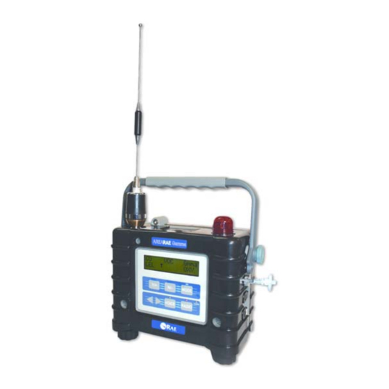
OPERATION OF AREARAE-Gamma 2.1 Physical Description Figure 2-1 Front View - Main Components 1. LCD Display with Backlight 2. Audible Alarm Port 3. Red LED Alarm Light 4. Handle 5. Antenna... - Page 17 OPERATION OF AREARAE-Gamma Figure 2-2 Right Side View - Main Components 1. Gas inlet port 2. Serial communication port for PC interface 3. Charger port – power jack connects AreaRAE-Gamma to external DC for charging 4. External Filter...
- Page 18 OPERATION OF AREARAE-Gamma Figure 2-3 Left Side View - Main Components 1. Battery Pack 2. Gas outlet 3. Mounting conduit...
-
Page 19: Keys And Displays
OPERATION OF AREARAE-Gamma 2.2 Keys and Display Charge Status Radio On/Off Figure 2-4 AreaRAE-Gamma Display and Keypad Table 2.1 Key Functions During Normal Operation Function Turn power on/off [MODE] Choose different display mode Toggle backlight on/off [N/-] Answer “No” Decrease values Alarm test and alarm acknowledgment Turn latched alarm off... -
Page 20: Turn Power On/Off
OPERATION OF AREARAE-Gamma 2.3 Turn Power On/Off To turn ON Press [MODE]. The audio buzzer will beep once, and the screen will display the following, in order: • “ON!” • “Multi-Gas Radiation Monitor Version n.nn” (the software version) • Custom power-on-name, which can be changed by the customer using the ProRAE Suite Software •... -
Page 21: Data Protection
OPERATION OF AREARAE-Gamma 2.4 Data Protection When the monitor is turned off, all the current real-time data including TWA, STEL, Peak and elapsed time are erased. However, the datalog data is preserved in non-volatile memory. Even if the battery is disconnected, the datalog data will not be lost. -
Page 22: Modes Of Operation
OPERATION OF AREARAE-Gamma 2.5 Modes of Operation The AreaRAE-Gamma offers three different modes of operation: • Text Mode • Display Mode • Program Mode... -
Page 23: Text Mode
OPERATION OF AREARAE-Gamma 2.5.1 Text Mode The Text Mode is AreaRAE Gamma’s default setting. The monitor will toggle between the Instantaneous Gas Concentration reading and the Sensor Name after the monitor is turned on. The user can press [MODE] to see the Instantaneous Gas Concentration reading, Battery Voltage or may enter the PC Communication menu. -
Page 24: Display Mode
OPERATION OF AREARAE-Gamma 2.5.2 Display Mode The Display Mode includes all the information from Text Mode in addition to the options listed below. See Section 4.3 Entering Programming Mode for details. To access each display, press [MODE] once. 1. The instantaneous reading and sensor names alternate every second on the display. - Page 25 OPERATION OF AREARAE-Gamma 3. The accumulated dosage display shows the total radiation dosage since the last reset. Press [Y/+] to clear the dosage reading. TOX1 Gamma Accumulated Dose = 1.00 µRem 4. The peak reading is the highest reading of each gas concentration since the monitor was turned on.
- Page 26 OPERATION OF AREARAE-Gamma 7. The TWA reading only applies to VOC and toxic gases. The reading is the accumulated reading of the gas concentration divided by 8 hours since the monitor was turned on. The reading is updated in every minute is indicated by the “TWA”...
- Page 27 OPERATION OF AREARAE-Gamma NOTE: It is very important that the Radio button is turned off before attempting to communicate with the PC. Connect the monitor to the serial port on a PC. The monitor is ready to receive any command from the PC. Press [MODE] again to return to the first display.
-
Page 28: Program Mode
OPERATION OF AREARAE-Gamma 2.5.3 Program Mode The user may perform all Display Mode functions. See Section 4.3 Entering Programming Mode for details. Displays The twelve functions are arranged in a round robin sequence: Instantaneous Unit Display Reading and Sensor Name Accumulated Dosage (alternating displays) PC Comm? -
Page 29: Alarm Signals
OPERATION OF AREARAE-Gamma 2.6 Alarm Signals The built-in microprocessor continually updates and monitors gas concentration levels. It also compares the readings with programmed TWA, STEL, and Low & High instantaneous gas concentration alarm limit settings. Whenever the concentration exceeds any of the preset limits, the buzzer and red LED will immediately warn the user the alarm condition. - Page 30 OPERATION OF AREARAE-Gamma Table 2.2 Alarm Signal Summary Message on Condition Alarm Signal LCD Screen Gas exceeds 3 beeps & flashes Sensor Name “High Alarm” limit per second Gas exceeds 2 beeps & flashes Sensor Name “Low Alarm” limit per second Gas exceeds 1 beep &...
-
Page 31: Backlight
OPERATION OF AREARAE-Gamma 2.7 Backlight The LCD is equipped with a backlight to assist reading under poor lighting conditions. When the monitor is in Normal Operation mode, the backlight may be manually turned on by pressing and holding [N/-] for one second. Press [N/-] a second time to turn off. - Page 32 OPERATION OF AREARAE-Gamma 2.8 Alarm Limits & Calibration AreaRAE-Gamma is factory calibrated with standard calibration gas, and is programmed with default alarm limits as listed below. (See Section 4.4 Calibration of AreaRAE-Gamma and Section 4.5 Change Alarm Limits) Table 2.3 Alarm Limits & Calibration Gas ppm Cal Gas/ Balance Unit...
-
Page 33: Integrated Sampling Pump
OPERATION OF AREARAE-Gamma 2.9 Integrated Sampling Pump The AreaRAE-Gamma Multi-Gas Radiation Monitor includes an internal integrated sampling pump with programmable high (400cc) and low (300cc) flow rate settings. A low pump speed of ~300cc per minute is the factory default setting. -
Page 34: Datalogging
OPERATION OF AREARAE-Gamma 2.10 Datalogging The AreaRAE-Gamma Multi-Gas Radiation Monitor calculates and stores gas readings based on the user-specified datalogging period and type of measurement. Two types of gas measurements, average or peak concentration may be stored for each sensor for any datalogging interval. Datalogging intervals may be programmed from one second to sixty minutes in one-second increments. - Page 35 OPERATION OF AREARAE-Gamma Other Datalog options will automatically start and stop: Datalogging Event Each time a datalogging operation is initiated, a datalog event is created. Information, such as start time, datalogging period, alarm limits, etc. will be recorded in the event header, followed by the measurement data.
-
Page 36: Operation Of Accessories
OPERATION OF ACCESSORIES 3. Operation of Accessories The accessories for AreaRAE-Gamma include: • Battery charger • Alkaline battery adapter • External filter and remote sampling probe • Dilution fitting • Calibration adapter WARNING To reduce the risk of ignition of hazardous atmospheres, recharge battery only in area known to be non-hazardous. -
Page 37: Battery Charging Operation
OPERATION OF ACCESSORIES 3.1 Battery Charging Operation The charging circuit of the AreaRAE-Gamma is built into the monitor. It requires a regular AC to 15 V DC adapter (a wall mount transformer) to charge the monitor. 1. Connect the AC adapter (or the optional automotive charging adapter) to the charger port on the bottom of the AreaRAE-Gamma monitor. -
Page 38: Interchangeable Battery Packs
OPERATION OF ACCESSORIES 3.2 Interchangeable Battery Packs The Alkaline battery adapter supplied by RAE Systems Inc. is intrinsically safe. An alkaline battery adapter is supplied with each AreaRAE-Gamma kit. It may be used in place of the rechargeable Lithium-Ion battery pack to provide at least 24- hours of operation. - Page 39 OPERATION OF ACCESSORIES Recharging the Lithium-Ion Battery Pack 1. Turn off power of the AreaRAE-Gamma. 2. Connect the AC adapter (or the optional automotive charging adapter) to the charger connection port on the AreaRAE-Gamma monitor. 3. A red “charge” LED located on the front of the instrument will indicate that the battery is being charged.
-
Page 40: External Filter
OPERATION OF ACCESSORIES 3.3 External Filter ® The external filter is made of a PTFE (Teflon ) membrane with a 0.2 micron pore size to reduce liquid water from being sucked into the sensor manifold, which would cause extensive damage to the monitor. -
Page 41: Remote Sampling Probe Or Teflon Tubing
OPERATION OF ACCESSORIES 3.4 Remote Sampling Probe or ® Teflon Tubing ® A 15-foot (5M) length of Teflon tubing is supplied as a standard accessory with every AreaRAE-Gamma detector. An ® optional 6-foot Teflon remote sampling probe with a telescoping handle is also available for The user who need to probe hard-to-reach areas such as ceilings, storage tanks, underground manholes, etc. -
Page 42: Dilution Fitting
OPERATION OF ACCESSORIES 3.5 Dilution Fitting An optional dilution fitting can be installed with the remote ® sampling probe or Teflon tubing on the gas inlet port to dilute gas samples. This fitting is needed when the gas sample contains less than 15% oxygen. The combustible sensor will not function correctly when the oxygen concentration falls below 15%. -
Page 43: Calibration Adapter
OPERATION OF ACCESSORIES 3.6 Calibration Adapter The AreaRAE-Gamma should be calibrated with the external filter in place. The AreaRAE-Gamma calibration adapter is designed to slip over the external filter. During calibration, connect the calibration adapter to the cylinder of the calibration gas. - Page 44 PROGRAMMING AREARAE-Gamma 4. Programming AreaRAE-Gamma is built with a microprocessor to provide programming flexibility for the user. Authorized users may recalibrate the monitor, change alarm limits, change site ID, change user ID, change datalogging period, adjust the real- time clock, etc. Program Mode is menu-based to provide user-friendly operation.
-
Page 45: Program Mode
PROGRAMMING AREARAE-Gamma 4.1 Program Mode The AreaRAE-Gamma has three user modes: Text, Display and Program mode. See Section 4.3 Entering Programming Mode for details. The programming function allows the user to change the setup in the monitor, calibrate the monitor, modify the sensor configuration and enter user information, etc. -
Page 46: Keys Of Program Mode
PROGRAMMING AREARAE-Gamma 4.2 Keys for Program Mode Table 4.1 Programming Keys Function [MODE] Exit menu when press momentarily or exit data entry mode when pressed and held for 1 second Increase numerical value for data entry [Y/+] Answer “yes” [N/-] Decrease numerical value for data entry Answer “no”... -
Page 47: Entering Into Program Mode
PROGRAMMING AREARAE-Gamma 4.3 Entering Program Mode 1. Turn AreaRAE-Gamma monitor on. 2. Press and hold [MODE] and [N/-] for three seconds to enter Program Mode. This prevents the user from entering Program Mode by accident. 3. Security Level 0 or Level 2 - the monitor will enter Program Mode and the first menu item “Calibrate Monitor?”... - Page 48 PROGRAMMING AREARAE-Gamma User Mode Text Display Program Security Level Calibrate Monitor? Fresh Air Calibration? Multiple Sensor Calibration? Single Sensor Calibration? Modify Span Gas Value? Change LEL/VOC Span Gas? Change Alarm? Change High Alarm Limit? Change Low Alarm Limit? Change STEL Alarm Limit? Change Average Alarm Limit? Change Datalog? Clear All Data?
-
Page 49: Calibration Of Arearae-Gamma
PROGRAMMING AREARAE-Gamma 4.4 Calibration of AreaRAE-Gamma WARNING The calibration of all newly purchased RAE Systems instruments should be tested by exposing the sensor(s) to known concentration calibration gas before the instrument is used or put into service. For maximum safety, the accuracy of... -
Page 50: Fresh Air Calibration
PROGRAMMING AREARAE-Gamma 4.4.1 Fresh Air Calibration This procedure determines the zero point of the sensor calibration curve. To perform fresh air calibration, the calibration adapter and a bottle of fresh air (optional) are required. The bottle of fresh air contains 20.9% oxygen concentration and contains no organic, toxic or combustible gases or other impurities. -
Page 51: Sensor Calibration Time
PROGRAMMING AREARAE-Gamma 4.4.2 Sensor Calibration Time Please refer to the RAE website www.raesystems.com download Technical Note 114 (TN-114) Sensor Specifications and Cross Sensitivities for current data and information regarding sensor calibration time. Slowly responding sensors listed in TN-114 may require pre- exposure of the sensor to the gas immediately before initiating the calibration sequence. -
Page 52: Multiple Sensor Calibration
PROGRAMMING AREARAE-Gamma 4.4.3. Multiple Sensor Calibration This function simultaneously determines the second point of calibration curve for multiple sensors in the monitor. Mixed standard reference gases are needed to perform this procedure. The user may choose several gas mixtures to be used in multiple sensor calibration. - Page 53 PROGRAMMING AREARAE-Gamma NOTE: If the readings are very close to the span gas values, then the calibration was successful. If the readings are not close to the span gas values, then calibration has failed. Therefore, the user needs to verify that the span gas value settings in the unit match the given values on the gas bottle.
- Page 54 PROGRAMMING AREARAE-Gamma Cross Sensitivity Some sensors may show cross sensitivity to other gases. Therefore, it is important to choose the gas mixture carefully for the Multiple Sensor Calibration to avoid erroneous readings. For example, some VOC gases are known to cause erroneous readings by the CO sensor.
-
Page 55: Single Sensor Calibration
PROGRAMMING AREARAE-Gamma 4.4.4 Single Sensor Calibration This procedure determines the second point of the sensor calibration curve for a single sensor. A standard reference gas (span gas) is needed to perform this procedure. Table 2.2 (Alarm Limits and Conditions) shows the standard calibration gas which is typically used as the span gas at the factory. - Page 56 PROGRAMMING AREARAE-Gamma 2. This completes the single gas calibration procedure for one sensor. The display shows the single gas calibration submenu for a user to select another sensor or move to the next submenu, Modify Span Gas Value. 3. Turn gas flow off. Disconnect calibration tube from monitor. 4.
-
Page 57: Modify Span Gas Value
PROGRAMMING AREARAE-Gamma 4.4.5 Modify Span Gas Value This function allows the user to change the span values of the standard calibration gases. 1. The next submenu is “Modify Span Gas Value?” 2. Press [Y/+], and the following display will appear: TOX1 Gamma span... -
Page 58: Change Lel/Voc Span Gas
PROGRAMMING AREARAE-Gamma 4.4.6 Change LEL/VOC Span Gas This function allows the user to select a specific LEL or VOC gas to be used as the span gas during LEL or VOC gas calibration. 1. When the “Change LEL/VOC Span Gas?” submenu appears, press [Y/+]. - Page 59 PROGRAMMING AREARAE-Gamma 5. If the VOC sensor is installed and enabled, the display shows: TOX1 Gamma VOC Span =? Isobutylene Otherwise, the message “No VOC installed” will appear. 6. If the user does not want to change the VOC span gas, press [Y/+] to accept the current selection and exit this submenu.
-
Page 60: Change Alarm Limits
PROGRAMMING AREARAE-Gamma 4.5 Change Alarm Limits The user may change alarm limits of each sensor while in Program Mode. These are the submenus for changing the alarm limits: Change High Alarm limit? Change Low Alarm limit? Change STEL alarm limit? Change Average alarm limit? 1. - Page 61 PROGRAMMING AREARAE-Gamma Or if the Averaging Method is the Running Average, the AVG will display instead of the TWA. (See Section 4.7.9 Change Averaging Method) TOX1 Gamma 10.0 2. To modify this limit, starting from the left-most digit, use [Y/+] or [N/-] to change the digit value and press [MODE] momentarily to advance to the next digit.
-
Page 62: Change Datalog
PROGRAMMING AREARAE-Gamma 4.6 Change Datalog AreaRAE-Gamma monitor calculates and stores the gas readings at a specified interval. The user can change datalog setup from the Program Mode. The user can also program additional datalog options by downloading from the PC to the AreaRAE-Gamma monitor. -
Page 63: Clear All Data
PROGRAMMING AREARAE-Gamma 4.6.1 Clear All Data This function will erase all data stored in the non-volatile datalog memory. This does not change STEL, Peak, minimum concentration and run time values which are stored in the other location. 1. “Clear All Data?” is the second item in the Datalog submenu. -
Page 64: Change Datalog Period
PROGRAMMING AREARAE-Gamma 4.6.2 Change Datalog Period The datalog period can be programmed from 1 to 3,600 seconds (1 hour). 1. “Change Datalog Period?” is the third item in the Datalog Program submenu item. 2. Press [Y/+], the display shows “New Period = 0060” with the left-most digit flashing, where “0060”... -
Page 65: Select Data Type
PROGRAMMING AREARAE-Gamma 4.6.3 Select Data Type The user can choose to store either the average or the peak value during each datalog period. 1. When the “Select Data Type?” submenu item appears, press [Y/+], the display shows the current data type: “Data Type = Average?”... -
Page 66: Enable/Disable Datalog
PROGRAMMING AREARAE-Gamma 4.6.4 Enable/Disable Datalog The user can choose to enable or disable the datalogging function on each individual sensor. This allows The user to selectively log certain sensor readings of interest. 1. When the “Enable / Disable Datalog?” appears, press [Y/+]. -
Page 67: Change Monitor Setup
PROGRAMMING AREARAE-Gamma 4.7 Change Monitor Setup In the Program Mode, the user may change monitor setup or enter user information for the AreaRAE-Gamma monitor. Monitor Setup submenu: User Mode Diagnostic Mode Change Site ID? Change Unit ID? Change User ID? Change Host ID? Change Alarm Mode? Change Net ID? -
Page 68: Change Site Id
PROGRAMMING AREARAE-Gamma 4.7.1 Change Site ID The user needs to enter an eight-digit alphanumeric site ID in the Program Mode. This site ID will be included in the datalog report. 1. “Change Site ID?” is the first submenu item. Press [MODE] to choose one of them and press [Y/+], the display shows the current site ID: “Site ID = xxxxxxxx”... -
Page 69: Change User Id
PROGRAMMING AREARAE-Gamma 4.7.2 Change User ID The user can enter an eight-digit alphanumeric user ID in the Program Mode. This user ID will be included in the datalog report. 1. “Change User ID?” is the second submenu item. Press [Y/+] and the display shows the current user ID: ”User ID=xxxxxxxx”... -
Page 70: Change Alarm Mode
PROGRAMMING AREARAE-Gamma 4.7.3 Change Alarm Mode There are two different alarm modes: latched and auto reset in AreaRAE-Gamma that can be selected from the programming menu. 1. “Change Alarm Mode?” is the third submenu item. Press [Y/+], the display shows the current alarm mode selection: “Alarm Mode = Latched?”... -
Page 71: Change User Mode
PROGRAMMING AREARAE-Gamma 4.7.4 Change User Mode There are three different user modes: program, display and text in AreaRAE-Gamma that can be selected from the programming menu. 1. “Change User Mode?” is the fourth submenu item. Press [Y/+], the display shows the current user mode selection: “User Mode = Program?”... -
Page 72: Change Real-Time Clock
PROGRAMMING AREARAE-Gamma 4.7.5 Change Real-time Clock The AreaRAE-Gamma monitor is equipped with a real-time clock. The user can enter the correct date and time into the real-time clock in the Program Mode. 1. “Change Real-time Clock?” is the fifth submenu item. Press [Y/+], the display shows both the current date and time: “Date = April 01, ‘02”... -
Page 73: Change Light And Buzzer Mode
PROGRAMMING AREARAE-Gamma 4.7.6 Change Light and Buzzer Mode? The user has the option to turn the light and buzzer on/off to suit their needs. The factory settings are saved to have both the light and buzzer turn on during alarm conditions. However, after the user changes and saves the settings, that particular setting will appear the next time the user enters this menu to change the options again. -
Page 74: Change Password
PROGRAMMING AREARAE-Gamma 4.7.7 Change Password The user can modify the password from the monitor. 1. When the screen “Change Password?” appears, press [Y/+] and the display shows the current password: “Enter new password = xxxx” with the left most digit flashing. 2. -
Page 75: Change Pump Duty Cycle
PROGRAMMING AREARAE-Gamma 4.7.8 Change Pump Duty Cycle A duty cycle is the ration of the time the pump is on for ten- second periods. A 30% duty cycle would mean that the instrument turns the pump on for three seconds, and then turns the pump off for seven seconds. -
Page 76: Change Pump Speed
PROGRAMMING AREARAE-Gamma 4.7.9. Change Pump Speed There are two speed settings for the pump motor in the AreaRAE-Gamma that can be selected from the programming menu: low (default) and high. The “high” setting (400cc flow per minute) should be used for long lengths of tubing or when rapid changes in input conditions are expected. -
Page 77: Change Averaging Method
PROGRAMMING AREARAE-Gamma 4.7.10 Change Averaging Method There are three methods of calculation used in the averaging of the monitor. Using this selection can cause the calculation to be performed using an eight-hour time weighted average (TWA), the default, a running average (AVG), or none. The display indicator for whichever averaging type is selected will show on the LCD display wherever the average is indicated. -
Page 78: Change Display Language
PROGRAMMING AREARAE-Gamma 4.7.11 Change Display Language Users may choose to view the display menus in Spanish. Additional languages will be added in the future. 1. When the “Change Display Language?” screen appears, press [N/-] to keep the language setting in English. User will advance to next menu option “Set Temperature Unit?”... -
Page 79: Set Temperature Unit
PROGRAMMING AREARAE-Gamma 4.7.12 Set Temperature Unit? The user may change the temperature unit from Fahrenheit (factory setting) to Celsius or back to Fahrenheit from Celsius. 1. At the “Set Temperature Unit?” display, press [Y/+]. The next screen to appear will either be “Temperature Unit = Fahrenheit?”... -
Page 80: Change Sensor Configuration
PROGRAMMING AREARAE-Gamma 4.8 Change Sensor Configuration In the Program Mode, the user may change several sensor related configurations of the AreaRAE-Gamma monitor. The Sensor Configuration Submenu contains the various configurations: Change LEL/VOC Gas Selection? Enable / Disable Sensors? Change Dilution Ratio? Change PID Lamp Type? Change RAD Unit? Before these submenus are described, the term “Correction... -
Page 81: Correction Factors
PID sensor in Section 4.8.5 Change PID Lamp Type. A comprehensive list of correction factors for the LEL sensor, 10.6 eV and 11.7 eV PID sensors has been provided at the RAE website www.raesystems.com, under Technical Note 106 and Technical Note 156. 4-38... -
Page 82: Change Lel/Voc Gas Selection
PROGRAMMING AREARAE-Gamma 4.8.2 Change LEL/VOC Gas Selection This function allows the user to choose one of the pre-stored LEL or VOC gases in the monitor and calculate its correction factor relative to the LEL or VOC calibration gas. This factor will then be used during gas measurements to show the equivalent concentration of the selected LEL or VOC gas. - Page 83 PROGRAMMING AREARAE-Gamma 5. “1.00” is the calculated correction factor of the selected gas in Step 4. TOX1 Gamma Methane LEL Factor=1.00? 6. If the user does not want to modify the LEL correction factor, press [Y/+] and go to Step 8. To modify this factor, press [N/-] first.
- Page 84 PROGRAMMING AREARAE-Gamma 11. “1.00” is the calculated correction factor of the selected gas in Step 10. TOX1 Gamma Isobutylene VOC Factor=1.00? 12. If the user does not want to modify the VOC correction factor, press [Y/+] and exit the submenu. To modify this factor, press [N/-] first.
-
Page 85: Enable/Disable Sensor
PROGRAMMING AREARAE-Gamma 4.8.3 Enable/Disable Sensor This function allows the user to selectively enable or disable individual sensors in the AreaRAE-Gamma monitor. When a sensor is disabled, the sensor will not measure nor display the gas concentration. 1. “Enable / Disable Sensors?” is the second submenu. Press [Y/+]. -
Page 86: Change Dilution Ratio
PROGRAMMING AREARAE-Gamma 4.8.4 Change Dilution Ratio The user can insert an optional dilution fitting on the AreaRAE- Gamma gas inlet port to dilute the gas sample. The user can enter a dilution ratio (from 1 to 10) from the programming menu so that the reading can be compensated to show the actual concentration of the gas sample with the dilution fitting. -
Page 87: Change Pid Lamp Type
PROGRAMMING AREARAE-Gamma 4.8.5 Change PID Lamp Type This programming menu only applies to the monitor, which is equipped with a PID detector option. There are two different energy UV lamps available for the PID sensor: 10.6 eV and 11.7 eV. The user must select a lamp in order for the instrument to calibrate correctly. -
Page 88: Exit Program Mode
PROGRAMMING AREARAE-Gamma 4.9 Exit Program Mode To exit Program Mode from the first tier menu level, press [MODE] once. 1. Display shows an instantaneous reading of normal operation mode. 2. To exit Program Mode from 2nd tier submenu level, press [MODE] twice. -
Page 89: Theory Of Operation
THEORY OF OPERATION 5.0 Theory of Operation The AreaRAE-Gamma monitor uses one to five different sensors to measure a variety of gases. A newly developed Electrodeless discharge UV lamp is used as the high-energy photon source for the PID sensor (see Figure 5-1). The patented PID sensor will detect a broad range of organic vapors. - Page 90 THEORY OF OPERATION The PID sensor for this AreaRAE-Gamma monitor is constructed as a small cavity in front of the UV lamp. The other sensors are mounted next to the PID sensor. A diaphragm pump is installed inside the monitor enclosure to draw air sample into the sensor manifold and then distributed to all sensors.
-
Page 91: Maintenance
MAINTENANCE 6. Maintenance Figure 6-1 Internal Components of AreaRAE-Gamma 1. Gas Plate 2. Sensors 3. Dust filter 4. Pump... -
Page 92: Battery Replacement
MAINTENANCE 6.1 Battery Replacement When the display shows a flashing message “Bat”, the battery requires recharging. The battery may be replaced in the field (in area known to be non-hazardous) if required. It is recommended to recharge the AreaRAE-Gamma monitor upon returning from fieldwork. -
Page 93: Sensor Replacement
AreaRAE-Gamma monitor. The toxic sensor socket in the AreaRAE-Gamma monitor allows the user to plug in any sensor selected from the series of toxic sensors offered by RAE Systems Inc. 1. Turn AreaRAE-Gamma off. 2. Remove the battery pack. (See Section 3.2 Interchangeable Battery Packs) 3. - Page 94 MAINTENANCE Figure 6-2 Gas Plate of AreaRAE-Gamma Figure 6-3 Detailed Sensor Assembly of AreaRAE-Gamma 1. PID sensor 2. Toxic sensor 3. LEL sensor 4. Gamma sensor 5. O sensor...
- Page 95 MAINTENANCE 4. Refer to Figures 6-2 and 6-3, carefully unscrew the three screws that hold down the gas plate to the analog PCB and sensors. Remove the gas plate. 5. Identify the location of a specific toxic sensor and remove the sensor by gently pulling the sensor upward.
-
Page 96: Pid Sensor Cleaning / Replacement
MAINTENANCE 6.3 PID Sensor Cleaning This section only applies to a monitor that is equipped with the PID detector option. During the course of normal operation, a film of gas vapor may build up inside the PID sensor module and the UV lamp. The rate at which the film develops depends on the type and concentration of the vapors being sampled. - Page 97 MAINTENANCE 5. Dip the entire PID sensor into GC grade methanol. It is highly recommended that an ultrasound bath to be used to clean the sensor for at least 3 minutes. Then dry the sensor thoroughly. 6. If the lamp is operational, use a cotton swab to clean the flat window surface with GC grade methanol.
-
Page 98: Taking Care Of The Lamp
MAINTENANCE 6.4 Taking Care of the Lamp During the course of regular operation, the UV lamp will become contaminated. Therefore, the lamp requires periodic cleaning. The “Lamp” error is an indication of a problem with the lamp current. A dirty or contaminated sensor often causes high readings of the VOC sensor. -
Page 99: Sampling Pump Replacement
MAINTENANCE 6.5 Sampling Pump Replacement The sampling pump is positive displacement piston pump. When approaching the end of the specified lifetime of the pump, it will consume higher amount of energy and reduce its sample draw capability significantly. When this occurs, it is necessary to replace the pump. -
Page 100: Troubleshooting
TROUBLESHOOTING 7. Troubleshooting To aid the user in diagnosing the monitor, the monitor has a diagnostic mode that can display critical, low level parameters. Section 7.1 describes the Operation of the Diagnostic Mode. Section 7.2 summarizes possible encountered problems and suggested solutions. -
Page 101: Possible Problems And Solutions
TROUBLESHOOTING 7.1 Possible Problems & Solutions Problem Possible Reason Possible Solution No power after Drained battery Charge battery charging battery Defective battery Replace battery Microprocessor hang-up Disconnect then reconnect battery to reset computer No LED or LCD Defective LED or LCD Call authorized backlight backlight... - Page 102 TROUBLESHOOTING Problem Possible Reason Possible Solution Reading jumps Incorrect gas calibration Calibrate the around randomly sensor Low sensitivity to calibration gas Clean PID Check Sensor Cannot turn Microprocessor hang-up Disconnect and monitor off reconnect battery to reset computer Corrupted characters on Call authorized service center Calibration error...
-
Page 103: Appendix A. Lamp Troubleshooting Details
APPENDIX A Lamp Troubleshooting Details Cold Lamp Startup The UV lamp is made of a glass envelope and a UV window on one end of the envelope. The inside of the lamp is filled with low pressure gases. To turn on the lamp, a high voltage electric field is applied from the outside of the glass envelope. -
Page 104: Appendix B. Radio Communication Troubleshooting Guide
If the AreaRAE-Gamma is in ‘Low Bat’ alarm, then communication will fail. The battery pack must have at least 6.6V available for proper communication. If the RAE Link battery fails the communication will fail. RAE Systems strongly... - Page 105 To verify the functionality of the communication port, RAE Systems Com Port Checker Kit (part #029-0005-000) can be used. Simply follow the instructions provided with the Checker Program.
- Page 106 APPENDIX B Figure 2. Set Up>>RF Modem Port. Press F2 (A) to activate ‘Set Up’ dialogue box, and proceed to select communication port that the RAE Link is plugged into (B). 7. UNIT ID: If multiple sensing units are attempting to communicate with the same Host, then the units must all have a different Unit ID.
- Page 107 Unit’ from the ‘Advanced Tools’ bar (A), and proceed to select the number of units the controller will attempt to communicate with (B). If communication problems persist after going through steps one through eight, then please email RAE Systems at tech@raesystems.com. Updates: Watch for updates of this and all of other technical and application notes on the Internet at www.raesystems.com...
- Page 108 RAE Systems, Inc. Main Office 1339 Moffett Park Drive Sunnyvale, California 94089, USA Contact Numbers 408.752.0724 Telephone 408.752.0723 Instrument Sales 877. 723.2878 Tubes Sales 888.723.8823 Technical Support 888.723.4800 E-mail RaeSales@raesystems.com Tech@raesystems.com Website www.raesystems.com SPECIAL NOTE: Before returning the unit for service or repair, please obtain a Return Material Authorization (RMA) Number for proper tracking of your equipment.
Need help?
Do you have a question about the AreaRAE-Gamma PGM-5120 and is the answer not in the manual?
Questions and answers