
Related Manuals for Rae QRAE PLUS PGM-2000


Summary of Contents for Rae QRAE PLUS PGM-2000
- Page 1 QRAE PLUS PGM-2000/2020 MULTI-GAS MONITOR OPERATION & MAINTENANCE MANUAL Document Number: 015-4001-001 Revision G-1, December 2002...
- Page 2 B. Recharge batteries only in non-hazardous locations C. Do not connect external cable to serial interface jack in hazardous locations. D. Use RAE Systems Adapter P/N 500-0072 for connection to communication port and charging jack only in a non- hazardous area.
- Page 3 - READ BEFORE OPERATING - This manual must be carefully read by all individuals who have or will have the responsibility of using, maintaining, or servicing this product. The product will perform as designed only if it is used, maintained, and serviced in accordance with the manufacturer's instructions.
-
Page 4: Table Of Contents
Table of Contents 1. General Information 2. Operation 2.1. Physical Description…………………………….…… 2.2. Operation of Monitor…………………………………... 2.3. Alarm Signals………………………………………… 2-12 2.4. Backlight…………………………………………...….. 2-15 2.5. Preset Alarm Limits and Calibration……………..… 2-16 2.6. Datalogging…………………………………………..…. 2-17 3. Operation of Accessories 3.1. Battery Charging Operation…………………………… 3.2. - Page 5 NOTE: THE SYMBOL MEANS “CAUTION- RISK OF DANGER. CONSULT OPERATION AND MAINTENANCE MANUAL”.
- Page 6 Read and understand the instruction manual completely before operating or servicing. Use only RAE Systems battery packs, part number 015-3051, 015- 3052, or 015-3053. *Battery pack 015-3051 is approved for use in USA only. This instrument has not been tested in an explosive gas/air atmosphere having an oxygen concentration greater than 21%.
- Page 7 Nettoyer uniquement avec un chiffon humide. LA CALIBRATION La calibration de toute instruments de RAE Systems doivent être testé en exposant l’instrument a une concentration de gaz connue par une procédure dietalonnage avant de mettre en service l’instrument pour la première fois.
-
Page 9: General Information
GENERAL INFORMATION 1. General Information The QRAE Plus is a programmable multi-gas monitor designed to provide continuous exposure monitoring of toxic gases, oxygen and combustible gases for workers in hazardous environments. There are two models available: the PGM-2000, a pump unit, and the PGM-2020, a diffusion unit. - Page 10 GENERAL INFORMATION Table 1. QRAE Plus Specifications Dimensions: 3” L x 4.5” W x 1.8” H (7.6 cm x 11.4 cm x 4.3 cm) Weight: 15 oz (525 g) with battery Detectors: 2 Electrochemical toxic gases sensors 1 Electrochemical oxygen sensor 1 Catalytic/Thermal conductivity sensor for combustibles Battery:...
- Page 11 GENERAL INFORMATION Calibration: Two-point field calibration for fresh air and standard reference gas Three-point optional oxygen calibration Attachments: Rubber boot, belt clip, wrist strap Protection: Password protected calibration settings, alarm limits, and data Intrinsic Safety: UL Class I, Division I, Group A, B, C, D, and Class II, Division I, Group E, F, G (Europe) CE 0575...
- Page 12 GENERAL INFORMATION (non-condensing)
- Page 13 GENERAL INFORMATION Table 2. Range, Resolution & Response Time equipped with pump) 016-1171-000 0-100% 15 seconds 008-1161-000 0-30% 0.1% 15 seconds 008-1112-000 0-500 ppm 1.0 ppm 40 seconds 008-1111-000 0-100 ppm 1.0 ppm 35 seconds 008-1113-000 0-20 ppm 0.1 ppm 35 seconds 008-1114-000 0-250 ppm...
-
Page 14: Operation
OPERATION 2. Operation The QRAE PLUS Monitor is a compact multi-gas monitor. It gives real time gas measurements and alarms when gas levels exceed the preset limits. Before leaving the factory, default alarm limits are preset into the QRAE PLUS and the sensors are pre-calibrated with standard calibration gases. -
Page 15: Physical Description
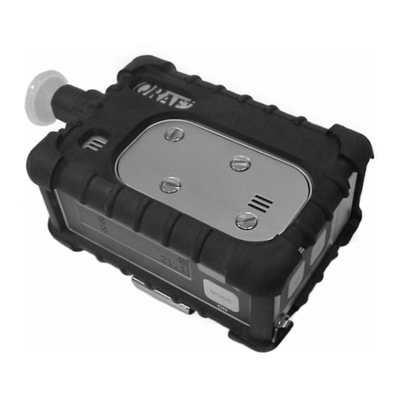
OPERATION 2.1. Physical Description Main components of the QRAE PLUS multi-gas monitor: Gas Exit Window Buzzer Window Sensor Cover Water Trap Filter Alarm and Charging LED Light Sensor Mode Key Liquid Crystal Display (LCD) Power Port Gas Inlet Communication Port Figure 1. - Page 16 OPERATION 1) The buzzer provides an audible warning when an alarm situation exists. 2) The water trap filter prevents water and dust from being drawn into and damaging the unit. 3) The Li-ion battery pack provides up to 20 hours of the continuous operation.
-
Page 17: Operation Of Monitor
OPERATION 2.2. Operation of Monitor Figure 3 shows the LCD and the keypad on the front panel of the monitor. The functions of the three keys during normal operation are summarized in the next page. LCD Display Light Sensor Alarm and Charging LEDs MODE and ON/OFF Key Figure 3. - Page 18 OPERATION Table 3. Key Functions in Normal Operation Mode [MODE] Hold for 1 second and release to turn ON the instrument. Hold for 5 seconds to turn OFF the instrument. Choose different displays. [N/-] Answer “No” to a question. Decrease a number. Toggle ON/OFF the backlight.
- Page 19 OPERATION The QRAE PLUS multi-gas monitor offers two different user modes of operation: 1. Basic mode is the simplest mode of operation. The monitor alternately displays the instantaneous concentration readings and the sensor names after the monitor is turned on. The user can press the [MODE] key to see critical data, battery voltage or enter the PC communication mode.
- Page 20 OPERATION Sensor Names / Instantaneous Readings [MODE] Comm with PC? Peak Values [MODE] [MODE] Print Reading?** Min. Values [MODE] [MODE] LEL Gas Name* STEL Values [MODE] [MODE] Start/Stop Datalog?* TWA Values [MODE] [MODE] Datalog Mode = XXX [MODE] [MODE] Date Time Run time Temp.
- Page 21 OPERATION To choose a specific display, press [MODE] one or more times until desired display appears. The following are brief explanations of each display. The Instantaneous Readings are the actual gas concentrations in parts per million (ppm) for toxic gases, percent by volume of oxygen and percent of LEL or percent by volume for combustible gases.
- Page 22 OPERATION 3) The PEAK reading is the highest reading of each gas concentration since the monitor was turned on, and it is shown on the display with the label “PEAK”. PEAK 21.5 4) The MINimum reading is the lowest reading of each gas concentration since the monitor was turned on and it is shown on the display with the label “MIN”.
- Page 23 OPERATION 8) The Battery Voltage screen displays the current battery voltage in volts. The shut down voltage is also shown. Battery = 4.0 V Shut off at 3.1 V Note: The battery pack will charge up to 4.0 volts when fully charged.
- Page 24 LEL gas = Methane 12) If the Serial Printer option is enabled through the Pro-RAE Suite, a screen called “Print Reading?” is shown. Connect the RAE Serial Printer to the serial port of the monitor.
-
Page 25: Alarm Signals
OPERATION 2.3. Alarm Signals The built-in microcomputer constantly monitors and updates gas concentrations and compares them with the programmed alarm limits (TWA, STEL, Low and High). Whenever a gas concentration exceeds any of the preset limits, the buzzer, red flashing LED, vibration alarm and the backlit LCD are activated immediately to warn the user of a potentially hazardous condition. - Page 26 OPERATION See Table 4 for the summary of the alarm signals. Some of these error messages will also be discussed in Chapter 7. When the low battery alarm occurs, there will be approximately 20-30 minutes of operating time remaining. When the battery voltage falls below 3.1V, the monitor will shut down automatically.
- Page 27 OPERATION It is possible to setup the QRAE PLUS from a PC or in programming mode so that when an alarm condition occurs, the alarm signals stay on even after the alarm condition is no longer present. This is called the “latching alarm” mode. The default mode is to automatically reset the alarm signal when the alarm condition is cleared (see Chapter 4 for details on how to set the alarm mode).
- Page 28 OPERATION Table 4. Alarm Signals and Reset Condition Alarm Signal Message on Alarm Reset by the LCD Gas exceeds 3 beeps/flashes Sensor name Move away from the “High Alarm” limit per second / and “High” gas. Vibration Gas exceeds 2 beeps/flashes Sensor name Move away from the “Low Alarm”...
- Page 29 OPERATION Alarm Signal Testing: Under normal non-alarm conditions, it’s possible to test the QRAE PLUS buzzer, vibration alarm, LED, and backlight by pressing [Y/+] momentarily. The buzzer, vibration alarm, LED and backlight will activate once to indicate that these alarm signals are functioning correctly. 2-16...
-
Page 30: Backlight
OPERATION 2.4. Backlight The display is equipped with an LED backlight to assist in reading the display under poor lighting conditions. In Manual mode, this backlight can be turned on manually by holding the [N/-] key for one second in normal operation. The backlight can be turned off by pressing [N/-] a second time. - Page 31 OPERATION 2.5. Preset Alarm Limits & Calibration The QRAE PLUS Multi gas monitor is factory calibrated with standard calibration gas, and is programmed with default alarm limits as listed below. Refer to Section 4 for programming procedures if new calibrations or alarm limits are required. Table 5.
-
Page 32: Datalogging
OPERATION 2.6. Datalogging This function applies only to datalogging monitors. The QRAE PLUS multi-gas monitor calculates and stores the gas readings based on a user-specified datalogging period and the type of measurement. Two types of gas measurements, average or peak concentration, can be stored for each sensor during each datalogging interval. - Page 33 OPERATION A new datalog event is created when the datalogging is resumed. 2-20...
-
Page 35: Operation Of Accessories
OPERATION OF ACCESSORIES 3. Operation of Accessories The accessories for the QRAE PLUS monitor include: • Li-Ion Battery & AC-DC Adapter (RAE 500-0036-000, CSA/UL approved) • Alkaline Battery Adapter • Water Trap and C-Filters WARNING! To reduce the risk of ignition of hazardous atmospheres, recharge battery only in area known to be non-hazardous. -
Page 36: Battery Charging Operation
Battery Charging Operation The charging circuit of the QRAE PLUS is built into the monitor. It only needs a 120 VAC to 12 VDC adapter (RAE 500-0036- 000, CSA/UL approved) to charge the monitor. Note: For European markets, Adapter P/N 500-0072 is required. -
Page 37: Alkaline Battery Adapter
OPERATION OF ACCESSORIES 3.2. Alkaline Battery Adapter The AA Alkaline battery adapter supplied by RAE Systems is intrinsically safe! An alkaline battery adapter is supplied with each QRAE PLUS kit. It accepts three AA alkaline batteries (Duracell MN1500 or Energizer E-91 only) and can be used in place of the Li-ion battery pack, as shown below, to provide approximately 6 hours of operation. -
Page 38: Water Trap And C-Filters
OPERATION OF ACCESSORIES 3.3. Water Trap and C-Filters ® The water trap filter is made of PTFE (Teflon ) membrane with a 0.2 micron pore size to prevent water from being sucked into the sensor manifold, which would cause extensive damage to the monitor. -
Page 39: Programming
PROGRAMMING 4. Programming The QRAE PLUS monitor is built with a microcomputer to provide programming flexibility for a variety of users. Authorized users can re-calibrate the monitor, change the alarm limits, change site ID, user ID, datalogging period, real time clock, etc. Menu-driven programming provides intuitive end-user operation. -
Page 40: Programming Mode
PROGRAMMING 4.1. Programming Mode The QRAE PLUS has two user modes: Basic and Advanced mode. Advanced mode offers complete accessibility to the programming menus. There are also three security levels to control the access of the QRAE PLUS programming mode. They are security levels 0, 1, and 2. - Page 41 PROGRAMMING To enter the programming mode, hold down the [MODE] and [N/-] keys simultaneously for three seconds. Depending on the security level, the display will be different according to Appendix A. - Security “Level 0” - “Display Only! Cannot enter..” - Security “Level 1”...
-
Page 42: Keys For Programming Mode
PROGRAMMING 4.2. Keys for Programming Mode The three keys perform a different set of functions during the programming mode as summarized below. Table 6. Key Functions in Programming Menu [MODE] Exit one tier of the menus when pressed momentarily or exit data entry mode when pressed and held for 1 second [Y/+] Increase an alphanumerical value for data entry Answer “yes”... -
Page 43: Calibration
PROGRAMMING 4.3. Calibration WARNING! The calibration of all newly purchased RAE Systems instruments should be tested by exposing the sensor(s) to known concentration calibration gas(es) before the instrument is put into service the first time. For maximum safety, the accuracy of the QRAE PLUS should be checked by exposing the sensor(s) to known concentration calibration gas(es) before each day’s use. - Page 44 PROGRAMMING Pumped Instruments The preferred calibration methods for monitors with pumps are ones that maintain the gas at atmospheric pressure. Such methods include the open cup, open tube, or “Tee” methods, in which the calibration gas flow is higher than the pump draw, and excess gas flows out freely beside the inlet probe.
- Page 45 PROGRAMMING Diffusion Instruments QRAE PLUS diffusion monitors must be calibrated using a fixed flow regulator with a flow rate between 0.5 and 1.0 liters per minute. Diffusion monitors are supplied with a special calibration adapter that covers the gas diffusion port. Sensor Calibration Time Slowly responding sensors listed in the table below may require pre-exposure of the sensor to the gas immediately before...
-
Page 46: Fresh Air Calibration
PROGRAMMING Calibration Time Stamp When a single or multiple sensor span calibration is performed, a time stamp will be stored in the non-volatile memory. This information will be included in the datalogging report. 4.3.1. Fresh Air Calibration This procedure determines the zero point of the sensor calibration curve. - Page 47 PROGRAMMING Press the [Y/+] key to accept the multiple sensor selection and start the calibration, or press the [N/-] key to modify the sensor selection and go on to Step 4. - - - 2. Turn on the valve of the mixed gas cylinder to start the flow of the span gas when the display shows “Apply Mixed Gas.”...
-
Page 48: Single Sensor Calibration
PROGRAMMING calibration option is needed for 0% oxygen calibration. See next section for single gas calibration. 5. Press the [MODE] key momentarily to move from one sensor location to the next one. Repeat Step 4 until all of the sensors that need to be calibrated during multiple sensor calibration are selected. - Page 49 PROGRAMMING pick 2. Oxygen Calibration: a) Press the [MODE] key twice to move to OXY, then press [Y/+] to select the highlighted OXY sensor and start the calibration. b) If the oxygen calibration type is 3-point calibration (see Section 4.3.6 on oxygen calibration type), that is 20.9% (air), 0% (99.9% N ), and 19.5% calibration, the display shows:...
-
Page 50: Modify Span Gas Value
PROGRAMMING 4.3.4. Modify Span Gas Value This function allows the user to change the span values of the standard calibration gases. 1. If “Modify Span Gas Value?” is chosen in the calibration sub- menu, the display will show: span 19.5 A cursor is blinking at the first digit of the first Span value. -
Page 51: Change Lel Span Gas
PROGRAMMING 4.3.5. Change LEL Span Gas This function allows selection of the gas to be used for span calibration of the LEL sensor. The correction factor for the measurement gas (Appendix B) is automatically divided by the correction factor for the span gas selected here, to obtain a new factor for the combination of gases. -
Page 52: Oxy Calibration Type
PROGRAMMING 4.3.6. OXY Calibration Type The QRAE PLUS allows both 2-point and 3-point O sensor calibrations (99.9% nitrogen or other inert gas). The 2-point calibration is at 20.9% during “fresh air zero” and 0% in single sensor calibration. The 3-point calibration is at 20.9% during “fresh air zero”, and at both 19.5% and 0% in sub- menus of the single sensor calibration. -
Page 53: Change Alarm Limits
PROGRAMMING 4.4. Change Alarm Limits In the programming mode, the users may change alarm limits of each sensor for the QRAE PLUS Monitor. The Change Alarm Limit Sub-Menu in advanced mode: Change High alarm limit? Change Low alarm limit? Change STEL alarm limit? Change Average alarm limit? 1. - Page 54 PROGRAMMING HIGH 23.5 19.5 STEL Depending on the selected averaging type from the “Change Averaging Method?” menu (see Step 1). 2. To modify these alarm limits, start at the left-most digit. Use the [Y/+] or [N/-] key to change the digit value and press the [MODE] key momentarily to advance the cursor one digit to the right.
- Page 55 PROGRAMMING 4.5. Change Datalog The QRAE PLUS monitor calculates and stores the gas readings at specified intervals. The user can change the datalog setup in the programming mode. Users can also program additional datalog options using a PC and download them to the monitor (see ProRAE Suite Manual for details).
-
Page 56: Change Monitor Setup
PROGRAMMING 4.6. Change Monitor Setup Users may change the monitor setup, as shown below, or enter personal information into the QRAE PLUS: Change Site ID? Change User ID? Change Alarm Mode? Change User Mode? Change Real Time Clock? Change Backlight Mode? Change Password? Change Pump Speed? Change Averaging Method? - Page 57 PROGRAMMING 6) Backlight Mode – manual or automatic. If manual mode is chosen, pressing the [N/-] key will turn on the LCD backlight. Automatic mode allows the backlight to turn on when the ambient light falls below a threshold level preset in the monitor.
-
Page 58: Change Sensor Configuration
PROGRAMMING 4.7. Change Sensor Configuration This sub-menu allows the user to change the following sensor related options on the QRAE PLUS monitor: Change LEL/VOL Sensor Type? * Enable / Disable Sensor? Change LEL Gas Selection?** Note: Combination LEL/VOL Sensor is not available in North America. -
Page 59: Change Lel/Vol Sensor Type
PROGRAMMING measured value of the LEL sensor into equivalent concentration of the pentane gas. Note 1: Using the correction factor provides an estimate the target measurement gas. For greatest accuracy, it is necessary to calibrate the LEL sensor directly with the target gas. Note 2: Using the correction factor does not make the sensor specific to that gas. - Page 60 PROGRAMMING CAUTION! Auto-range should be selected only when the methane is used as the calibration and target gas. 4-22...
-
Page 61: Enable / Disable Sensor
PROGRAMMING 4.7.2. Enable / Disable Sensor This function allows the user to selectively enable or disable individual sensors in the QRAE PLUS monitor. When a sensor is disabled, the unit will not measure or display gas concentrations of that type. 1. -
Page 62: Change Lel Gas Selection
PROGRAMMING 4.7.3. Change LEL Gas Selection This function allows selection of the measurement gas for the LEL sensor from the on-board compound library. The correction factor for this gas is automatically divided by the correction factor for the span gas selected previously, to obtain a new factor for the combination of gases. - Page 63 PROGRAMMING 4. The display will now show: Methane LEL factor = 1.00? “1.00” is the calculated correction factor of the selected gas in Step 4. If you do not want to modify the LEL correction factor, press the [MODE] key and go to Exit. To modify this factor, press [N/-] key first.
-
Page 64: Exit Programming Mode
PROGRAMMING 4.8. Exit Programming Mode 1. To exit programming mode from the first tier of menus, press the [MODE] key once. The display will return to the instantaneous readings of normal operation. 2. To exit programming mode from the second tier of menus press the [MODE] key twice. -
Page 66: Computer Interface
COMPUTER INTERFACE 5. Computer Interface Every QRAE PLUS that is ordered with datalogging enabled additionally includes a ProRAE Suite software package and a serial computer-interface cable. Please refer to the ProRAE Suite Manual for installation instructions. -
Page 68: Theory Of Operation
THEORY OF OPERATION 6. Theory of Operation The QRAE PLUS monitor uses up to four different sensors to measure a variety of gases. A newly developed thermal conductivity sensor is combined with a catalytic gas sensor to measure combustible gases. Several different types of toxic gas sensors are offered. - Page 69 THEORY OF OPERATION The sensors are mounted next to the gas inlet probe. A diaphragm pump can be installed inside the monitor to draw an air sample into the sensor manifold and then be distributed to all the sensors. A single microcomputer chip is used to control the operation of the alarm buzzer, LED, pump and light sensor.
-
Page 70: Maintenance
MAINTENANCE 7. Maintenance SENSOR COVER, 015-3036-000 Including: Gas plate, 015-2003-000 Gas plate cover, 015-2004-000 Gas plate foam, 015-2009-000 Screws X4, 015-2015-000 O-rings, 430-0112-000 & OXYGEN SENSOR 430-0115-000 (O2 Sensor, 008 -1161 -000) TOX2 SENSOR (H2S Sensor, 008 -1111- 001) LEL SENSOR, 016-1171-000 HOUSING TOP ASSEMBLY, 015-2901-000 TOX1 SENSOR... - Page 71 Sensors • Sampling pump • AC/DC adapter (RAE 500-0036-000, CSA/UL approved) Refer to Table 2 & Figure 11 for assembly and part number information when ordering new components. Cleaning: Use only a cloth dampened with water to wipe the unit. Apply gently while cleaning the display area.
- Page 72 MAINTENANCE The following guidelines should be followed when changing components: 1. Do not change the sensors or sampling pump, unless the related information in Chapters 2, 4, and 8 are fully understood and the diagnostic procedure is performed. 2. Turn off the unit and unplug the charger before changing a battery.
-
Page 74: Troubleshooting
TROUBLESHOOTING 8. Troubleshooting To aid diagnosis of the monitor, it has a diagnostic mode that displays critical, low level parameters. Section 8.1 describes the diagnostic mode. Section 8.2 summarizes the frequently encountered problems and suggested solutions. Turning the QRAE PLUS monitor on in diagnostic mode, and using the troubleshooting table in section 8.2, the user can narrow problems down to one or two areas and often correct the problem without having to return the monitor for repair. -
Page 75: Diagnostic Mode
TROUBLESHOOTING 8.1. Diagnostic Mode To place the monitor in diagnostic mode, first turn the monitor off. Next push and hold the [Y/+] and the [MODE] keys for at least two seconds. After the unit “beeps”, release both keys and the monitor will turn on in diagnostic mode. The monitor will display a “Diagnostic mode”... - Page 76 TROUBLESHOOTING Table 7. Displays in Diagnostic Mode Key Action Display Show raw readings [MODE] Show sensor name [MODE] Show battery voltage, and charge raw count [MODE] Adjust LCD contrast [MODE] Adjust Buzzer Frequency [MODE] Show LEL or VOL sensor raw readings [MODE] Show date, clock, battery voltage and temperature...
- Page 77 TROUBLESHOOTING Diagnostic displays: 1) Raw Sensor Readings The raw sensor readings provide a quick diagnosis for sensor response and sensitivity. If the raw reading is outside the normal ranges, the sensor or the unit may be defective. When a specific gas is applied to the monitor, the corresponding sensor’s raw reading should increase or decrease.
- Page 78 TROUBLESHOOTING This display shows the present raw reading of the LEL or of the combination LEL/VOL sensor. The top display shows the mode of the combustible sensor. The bottom line shows the instantaneous reading of raw counts from the LEL or VOL sensor.
- Page 79 TROUBLESHOOTING The pump current draw is higher when the pump is running at the high speed than when it is running at the low speed, so both thresholds need to be set separately. Press the [Y/+] key to adjust the low speed, press the [N/-] key to adjust the high speed.
-
Page 80: Troubleshooting Tips
TROUBLESHOOTING 8.2. Troubleshooting Tips Problem Possible Cause Possible Solution Cannot turn on Defective battery. Charge or replace battery. power after Microcomputer hang- Disconnect then connect charging battery battery to reset computer. No LED or LCD Wrong mode setting. Check and see if the backlight Defective LED or backlight is in automatic or... - Page 81 TROUBLESHOOTING...
-
Page 82: Appendix A. Programming Functions
APPENDIX A Programming Functions 1. Accessibility of calibration and programming functions Mode BASIC ADVANCED Security Level Calibrate Monitor? û ü* ü ü ü* ü Fresh Air Calibration? û ü* ü ü ü* ü Multiple Sensor Calibration? û ü* ü ü ü* ü... - Page 83 APPENDIX A ü- Function allowed * - Password required A - 2...
- Page 84 APPENDIX A 2. Full Programming Menu versus Key Operation To enter, press [N/-] and [MODE] together for 3 seconds. To return, press [MODE]. Calibrate Monitor? (Press [Y/+] to select menu) Fresh Air Calibration? Multiple Sensor Calibration? Single Sensor Calibration? Modify Span Gas Value? MODE Change LEL Span Gas ? OXY Calibration Type?
-
Page 85: Appendix B. Lel Correction Factors
APPENDIX B LEL Correction Factors Correction factors (CFs) for a number of commonly used compounds for the LEL sensor are on the facing page. The factors are measured relative to methane. After calibration to methane, multiply the reading by the factor to obtain the actual % LEL of the gas. - Page 86 APPENDIX B Correction Factors for LEL Sensors Compound LEL (Vol%)* Acetaldehyde Acetic acid Acetone Ammonia 15.0 Benzene Butadiene, 1-3- Butane, n- Butene, 1- Carbon monoxide 12.5 Cyclohexane Dichloromethane 13.0 Ethanol Ethene Ethyl acetate Ethylbenzene Ethyl ether Gasoline, whole Heptane, n- Hexane, n- Hydrogen Isobutane...
- Page 87 APPENDIX B Xylene, p- * Lower Explosion Limit of the gas in volume percent B - 3...
- Page 88 RAE Systems, Inc. Main Office 1339 Moffett Park Drive Sunnyvale, California 94089 Contact Numbers 408.752.0724 Telephone 408.752.0723 Instrument Sales 877.RAE.CUSTOMER (877.723.2878) Tubes Sales 888.RAE.TUBE (888.723.8823) Technical Support 888.723.4800 E-mail RaeSales@raesystems.com Tech@raesystems.com Website www.raesystems.com...
Need help?
Do you have a question about the QRAE PLUS PGM-2000 and is the answer not in the manual?
Questions and answers