
Related Manuals for Nidek Medical OPD-Scan III


Summary of Contents for Nidek Medical OPD-Scan III
- Page 1 REFRACTIVE POWER / CORNEAL ANALYZER REFRACTIVE POWER / CORNEAL ANALYZER OPD-Scan III OPD-Scan III OPERATOR’S MANUAL OPERATOR’S MANUAL...
- Page 2 Original instructions : 34-14, Maehama, Hiroishi-cho, Gamagori, Aichi 443-0038, Japan NIDEK CO., LTD. Telephone: +81-533-67-6611 (Manufacturer) Facsimile: +81-533-67-6610 : 3F Sumitomo Fudosan Hongo Bldg., 3-22-5, Hongo, NIDEK CO., LTD. Bunkyo-Ku, Tokyo 113-0033, Japan (Tokyo Office) Telephone: +81-3-5844-2641 Facsimile: +81-3-5844-2642 : 47651 Westinghouse Drive, Fremont, California 94539, U. S. A. NIDEK INCORPORATED Telephone: +1-510-226-5700 (United States Agent)
-
Page 3: Safety Precautions
Use this device properly and safely. BEFORE USE, READ THIS MANUAL. This operator’s manual includes operating procedures, safety precautions, and specifications for the NIDEK REFRACTIVE POWER / CORNEAL ANALYZER, OPD-Scan III. Cautions for safety and operating procedures must be thoroughly understood before using this device. -
Page 4: Before Use
Usage precautions Before use • Do not use the device for other than the intended purpose. CAUTION NIDEK will not assume responsibility for accidents or malfunction caused by misuse. • The safety precautions and operating procedures must be thoroughly understood prior to operation of the device. - Page 5 • Do not use any power cord other than the one provided. Do not use the provided CAUTION power cord for any other instrument. Malfunction or fire may result. • Install the device in area where the outlet that the mains plug is inserted into is easily accessible during use.
-
Page 6: During Use
During use • Perform visual and operational checks before using the device. Do not use the CAUTION device if any error is found. Use of a malfunctioning {device} will not produce the expected results and may cause troubles or lead to inappropriate diagnoses that may induce health hazards. •... - Page 7 Installing any other Windows application software may lead to abnormal operation of the OPD-Scan III and loss of stored data. In addition, the warranty may not cover the OPD-Scan III if Windows application software other than the OPD-Scan III software is installed.
- Page 8 CAUTION electrical and electronic equipment that may disturb, or be disturbed by, other equipment. The OPD-Scan III complies with these requirements as shown in the tables in “6.3 EMC (ELECTROMAGNETIC COMPATIBILITY) (page 319)”. Follow the guidance in the tables for use of the device in an electromagnetic environment.
- Page 9 40 times. Spectrum output of all light source during measurement (maximum light intensity) OPD-Scan III Relative Spectral Distribution Wavelength (nm) * The values in the graph were obtained using separate measurement devices.
- Page 10 Patient environment The patient environment is the volume of space in which contact can occur between the patient and any part of the device (including connected devices) or between the patient and any other person(s) touching the device (including connected devices). Use devices that comply with IEC60601-1 in the patient environment.
-
Page 11: After Use
After use • This device uses a heat-sensitive printer paper. To keep the printed data for a long CAUTION period of time, make copies of the printouts. The paper degrades over time and the printed data may become illegible. • When the device is not in use, turn off the power switch and put the dust cover over the device. - Page 12 Maintenance and check • Only service personnel trained by NIDEK are allowed to repair and service the device. CAUTION NIDEK assumes no responsibility for any adverse events resulting from improper ser- vicing. • When performing maintenance work, secure a sufficient maintenance space. Maintenance work in an insufficient space may result in injury.
- Page 13 Connection to Network • To share the database with PCs installed with OPD Software for External PC, do not CAUTION connect them to the network that can connect to the Internet. Configure a local network only with the device, PCs installed with OPD Software for External PC, and other related instruments or software such as Final Fit.
-
Page 15: Table Of Contents
Table of Contents 1. BEFORE USE ........1 1.1 Device Outline . - Page 16 2.5.2 OPD/CT multi measurement (Multi measurement mode) ....72 2.6 OPD Measurement ........... . 77 2.6.1 OPD single measurement .
- Page 17 3.1.16 Zonal Refraction map ..........183 3.2 Explanation of Summaries .
- Page 18 Setting barcode reader and magnetic card reader ......266 4.6.3 Copying temporary data (OPD-Scan III)....... . 269 4.6.4 Using on-screen keyboard (OPD-Scan III) .
- Page 19 6.2 List of Abbreviations ..........317 6.3 EMC (ELECTROMAGNETIC COMPATIBILITY) .
-
Page 21: Before Use
Keratometry data simulated based on analysis of the captured placido ring image When an external PC installed with OPD Software for External PC is connected to the OPD-Scan III, operations such as viewing or export of measurement data can be performed with the PC. -
Page 22: Intended Use
BEFORE USE: Intended Use Intended Use The OPD-Scan III is a diagnostic instrument that is indicated for use: Mapping of refractive power distribution of the eye, by measurement and analysis of spherical power, cylindrical power, and cylinder axis. The measurement and analysis of corneal curvature (corneal refractive power), cylindrical power, and cylinder axis of the cornea. -
Page 23: Device Configuration
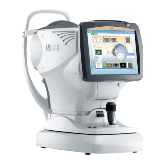
BEFORE USE: Device Configuration Device Configuration Front view 1. Touch screen 2. Start button 5. Locking lever 3. Joystick 4. Power switch Connector panel 7. Cover open button 6. Printer 1. Touch screen Displays various operation screens, examination data, and maps. The device can be operated by touching the buttons on the screen. - Page 24 BEFORE USE: Device Configuration The touch screen is a 10.4-inch color LCD. It can be tilted by pulling its bottom and fixed at various angles. If the operator uses the device in a standing posture, tilt the screen at a suitable angle.
-
Page 25: Connector Panel
BEFORE USE: Device Configuration Connector panel Provides the connectors for the keyboard, mouse, and external devices. • Equipment connected to the analog or digital interfaces must be certified according CAUTION to the representative appropriate national standards (such as EN 60601-1 and IEC 60601-1). - Page 26 BEFORE USE: Device Configuration 11. Ethernet connector Used to connect the device to an Ethernet network. Setting up of a LAN is required for connection to an Ethernet network. Set up a LAN in the LAN Settings window that appears by pressing the LAN button in the Maintenance screen. 12.
- Page 27 BEFORE USE: Device Configuration Rear view 14. Forehead rest 17.Eye level marker 15. Measuring window 18. Chinrest up/down button 16. Chinrest 19. PD window 14. Forehead rest Used to rest the patient’s forehead to restrict head movement during measurement. Clean it for each patient. 15.
-
Page 28: Bottom View
BEFORE USE: Device Configuration Bottom view 20. Sockets for AR tray pins Cooling fan vent 22. Bottom cover 21. Power inlet (for servicing) 20. Sockets for AR tray pins When placing the device on the AR tray of the NIDEK system table, place it so that the pins on the AR tray are inserted into these sockets. -
Page 29: Screen Configuration
BEFORE USE: Screen Configuration Screen Configuration 1.5.1 Main Menu screen The Main Menu screen is displayed when the OPD-Scan III is activated and allows selection of the screen to proceed to. VERSION button Measurement button Patient Files button Maintenance button... - Page 30 Be sure to use this button, not the power switch, to turn off power to the device. Turning off power to the device using the power switch may cause failure of the device. In the case of OPD Software for External PC, pressing this button closes the OPD-Scan III software.
-
Page 31: Patient List Screen (Before Measurement)
BEFORE USE: Screen Configuration 1.5.2 Patient List Screen (before measurement) The Patient List screen (before measurement) allows selection of the patient for whom the measure- ment is going to be performed. Patient data brief information New Patient button Measurement button Easy search boxes Edit button Main Menu button... - Page 32 If multiple search conditions are entered, the AND search is executed. • The button for displaying the on-screen keyboard is effective only when the software runs on the OPD-Scan III device. In case of the OPD Software for External PC, only the names of the boxes are displayed instead of the buttons for displaying the on-screen keyboard.
- Page 33 BEFORE USE: Screen Configuration 11. Patient List Shows the existing patients. Select the row of the patient for whom the measurement is going to be performed. Pressing an item name (ID, Name, Sex, Group, or Last exam date) on top of the patient list sorts the data in ascending order.
- Page 34 BEFORE USE: Screen Configuration Search Option window Used to search patients using optional search conditions to facilitate patient selection. The AND search is executed together with the search conditions specified in the easy search boxes. 1) Press the Option button to display the Search Option window. 2) Specify the desired search conditions and press the OK button.
-
Page 35: Create Patient Window
BEFORE USE: Screen Configuration 1.5.3 Create Patient window The Create Patient window is used to create new patient data. It is displayed by pressing the New Patient button in the Patient List screen. ID button/box Sex select button Name button/box Physician button/box Group button/box Detail button... - Page 36 Used to cancel the input patient data and return to the Patient List screen. • The button for displaying the on-screen keyboard is effective only when the software runs on the OPD-Scan III device. In case of the OPD software for external PC, only the names of the boxes are displayed instead of...
-
Page 37: Patient List Screen (Before Displaying Summary)
BEFORE USE: Screen Configuration 1.5.4 Patient List Screen (before displaying summary) The Patient List screen (before displaying summary) allows selection of the patient for whom a sum- mary (map) is to be displayed from the measurement data stored in the database. The patient data can be edited as well. -
Page 38: Measurement Screen
BEFORE USE: Screen Configuration 1.5.5 Measurement screen The Measurement screen allows measurement of the corneal curvature and the whole eye refraction. Measurement mode button Auto shot button Tracking button Patient data button Latest data Verify button Main Menu button Measure Option button Delete button Minimum pupil mark Focus indicator... - Page 39 BEFORE USE: Screen Configuration 3. Tracking button Used to toggle use the auto tracking function (that automatically performs alignment). The auto tracking function in the forward and back, right and left, and up and down directions is enabled. The auto tracking function in the right and left, and up and down directions is enabled.
- Page 40 BEFORE USE: Screen Configuration 11. Focus indicator Indicates the distance between the main body and the patient’s eye. Operate the joystick until the ( ) mark indicates that focus is proper. 12. Alignment target Used as a guide to adjust the patient’s eye to the center of the screen. 13.
-
Page 41: Verify Examination Quality Screen
BEFORE USE: Screen Configuration 1.5.6 Verify Examination Quality screen The Verify Examination Quality screen allows verification of the measurement data in Single measure- ment mode. This screen is automatically displayed when the measurement is complete. This screen can also be set to be displayed when the Verify button is pressed in the Measurement screen. - Page 42 BEFORE USE: Screen Configuration 2. Data verify button Used to verify the measurement data being displayed to be proper and save it to the database. This button can be set to execute printing or outputting data to electronic medical record (EMR) with the “Accept Button Handling”...
- Page 43 BEFORE USE: Screen Configuration 8. All Data button Used to move to the Verify Multi Measurement screen. The Verify Multi Measurement allows verification of all the measurement data and changing of the measurement to be selected. If the Verify Multi Measurement screen is moved from the Verify Examination Quality screen, saving of data cannot be executed unlike in Multi measurement mode.
-
Page 44: Verify Multi Measurement Screen
BEFORE USE: Screen Configuration 1.5.7 Verify Multi Measurement screen The Verify Multi Measurement screen allows selection of data to be saved to the database in Multi measurement mode. When measurement is finished with both eyes in Multi measurement mode, the Verify Multi Measure- ment screen is automatically displayed (when “Auto Display”... - Page 45 BEFORE USE: Screen Configuration 2. Verify button Used to save the selected data to the database, and move to the Summary screen or the Patient List screen. This button can be set to move to the Summary screen or the Patient List screen with the “Accept Button Handling” setting in the Settings screen (Measurement tab).
- Page 46 BEFORE USE: Screen Configuration 10. Pupil image (photopic vision) Shows the pupil image in mesopic vision. White line Pupil contour in mesopic vision. White cross Pupil contour in photopic vision. 11. CT measurement data SimK S “Refractive power@Angle” in steepest meridian direction SimK F “Refractive power@Angle”...
-
Page 47: Exam List Screen
BEFORE USE: Screen Configuration 1.5.8 Exam List screen The Exam List screen displays the examination data of the patient selected in the patient list as a list of thumbnail maps. Select the thumbnail of the desired examinatino data, then press the desired button according to the intended operation. - Page 48 BEFORE USE: Screen Configuration 4. Advance button (optional) Used to move to the Advance screen for the currently selected examination data. This button is enabled only when the license of the optional software “Advance” is installed. 5. IOL-Station button (optional) Used to move to the IOL-Station screen for the currently selected examination data.
- Page 49 BEFORE USE: Screen Configuration 10. Back button Used to return to the Patient List screen. 11. Image button Used to change the type of thumbnail list. Select from the menu that appears by pressing the button. Select “Cornea”, “Total”, “Internal”, “Total Cornea”, “Cornea Internal”, “Total Internal”, or “All”.
-
Page 50: Summary Screen
BEFORE USE: Screen Configuration 1.5.9 Summary screen The Summary screen allows viewing of a maximum of six maps in a single screen. In addition, maps can be enlarged by pressing the Enlarge button ( ) at the top left of each map. A summary offers desired information such as various maps, text data, and eye image. - Page 51 BEFORE USE: Screen Configuration 4. Pt. List button Used to move to the Patient List screen. Selection of the current patient is cancelled. 5. Pt. Exams button Used to display another examination data. Pressing this button displays the examination data number and the examination date in a list. The selected examination data is displayed in the same summary.
- Page 52 BEFORE USE: Screen Configuration 12. Map display area The map and analytical values are displayed in accordance with the selected summary. Pressing the map name, image name, or graph name buttons in the analytical value box (text map) enlarges the corresponding map, image, or graph.
-
Page 53: Maintenance Screen
BEFORE USE: Screen Configuration 1.5.10 Maintenance screen The Maintenance screen allows selection and execution of the desired maintenance operations. Maintenance menu buttons Maintenance menu buttons Displays the corresponding maintenance screen. Database Used to maintain the database. Backup/Restore Parameters Used to back up or restore the setting information for this device. The setting file is stored to an external memory to be used for restoration of the setting after replacement of the device. -
Page 54: Utility Screen
BEFORE USE: Screen Configuration 1.5.11 Utility screen The Utility screen allows operation of auxiliary function of the OPD-Scan III. Utility menu buttons Utility menu buttons Displays the corresponding utility screen. Import Used to import external OPD measurement data. Export Used to export OPD measurement data. -
Page 55: Settings Screen
BEFORE USE: Screen Configuration 1.5.12 Settings screen The Settings screen allows setting of various parameters: “Measurement”, “Print”, “Communication”, “Data Output”, “Summary”, “Parameter”, “Map Scale”, “List”, and “Other”. Main Menu button Setting parameter tab Restore Defaults button Save button Cancel button 1. -
Page 56: Opd Database Manager Screen
BEFORE USE: Screen Configuration 1.5.13 OPD Database Manager screen The OPD Database Manager screen allows selection and backup of the database. This screen is dis- played by pressing the Database button in the Maintenance screen. <Normal settings> <Advanced settings> Start button Stop button Linked Comp List button Local and Other computer... - Page 57 6. Minimize button Used to reduce the OPD Database Manager screen to the task bar. When using the OPD-Scan III regularly, make OPD Database Manager stay resident and minimized to the task bar. 7. Advanced Settings/Normal Settings button Used to toggle between the advanced settings and normal settings screens.
-
Page 58: Labels
BEFORE USE: Labels Labels Cautionary labels are provided on the device. If labels are curling up or characters fading and becoming barely legible, contact NIDEK or your autho- rized distributor. Indicates that important descriptions are contained in the operator’s manual and that the operator must refer to the operator’s manual prior to operation or maintenance. - Page 59 BEFORE USE: Labels For connection of the power cord, see “Before use” (page II). Side view Precaution regarding the power switch Precaution in cable connection See “2.2.3. Shut down” (page 46). See page IV‚ and “ Device Configuration (page 3)” in “1.4 Device Configuration”.
-
Page 60: Checking Contents
BEFORE USE: Checking Contents Checking Contents Unpack the contents from the shipping carton and check them. The standard accessories are as follows: • Main body • Printer paper (3 rolls) • Power cord • Dust cover • Pack of chinrest paper •... -
Page 61: Before First Use
BEFORE USE: Before First Use Before First Use Place the device on a stable table and connect the power cord to it. Place the main body on a stable table. Pull the main unit fully to the side on which the device is to be laid down, then gently lay down the device. - Page 62 BEFORE USE: Before First Use Turn on ( ) the power switch. The title screen is displayed on the touch screen and the device starts initializing. Title screen Confirm that the Main Menu screen is displayed. Main Menu screen Set the printer paper. See “4.3.
-
Page 63: Operating Procedure
OPERATING PROCEDURE Operation Flow [Measurement and printing → Saving of measurement result in database] Turning on the device 2.2.1 Start up (Page 44) Turn on power to the device, and change the parameter setting of the device. Inputting patient name 2.3 Patient List Screen Operation (Page 47) Measurement 2.4 Measurement (Page 57) -
Page 64: Start Up And Shut Down
Power switch The title screen appears and the device is ini- tialized. When power to the OPD-Scan III is turned on, the main body makes slight movement in hori- zontal directions to determine the initial position for auto tracking. It is not a failure of the device. -
Page 65: Recovery From Power Saving Mode
OPERATING PROCEDURE: Start Up and Shut Down • If the internal solid state disk (SSD) space is not enough, a message appears during the startup of the device to recommend freeing up the SSD space by the following methods: 1. Delete unnecessary patient data by pressing the Delete button in the Patient List screen. 2. -
Page 66: Shut Down
III? Yes/No” appears. Press “Yes”. The OPD-Scan III is shut down, and the power switch is automatically turned off. In case of the OPD software for external PC, the software becomes closed. Pressing the No button returns to the Main Menu screen. -
Page 67: Patient List Screen Operation
OPERATING PROCEDURE: Patient List Screen Operation Patient List Screen Operation 2.3.1 Patient List Screen Operation The Patient List screen allows selection of the patient for whom the measurement is going to be per- formed, or whose previous measurement data is going to be viewed. Patient data can be created, edited, or deleted as well. -
Page 68: Registering New Patient
OPERATING PROCEDURE: Patient List Screen Operation Main Menu button Used to return to the Main Menu screen. Delete button Used to delete the patient information and examination data selected in the patient list. When a patient is deleted, all examination data sets for the patient are deleted. To delete only examination data, move to the Exam List screen. - Page 69 OPERATING PROCEDURE: Patient List Screen Operation • When the measurement data is to be used for Final Fit, failure to input any of the patient ID, last name, first name, sex, and the date of birth disables creation of shot data. Inputting these items beforehand is recommended.
- Page 70 For the setting to enable the on-screen key- board, see "4.6.4 Using on-screen keyboard (OPD-Scan III) (Page 270)". Example of indications instead of buttons...
- Page 71 OPERATING PROCEDURE: Patient List Screen Operation • When the on-screen keyboard is being displayed, the hardware keyboard is disabled. However, the mouse can be used. • If the on-screen keyboard is displayed to edit the existing information, the information becomes automatically highlighted. Therefore inputting a character deletes the existing information.
- Page 72 OPERATING PROCEDURE: Patient List Screen Operation Input using keyboard If a keyboard is used, the information can be directly input in the boxes. Press the day, month, and year to select them, then overwrite them using the keyboard. If an inappropriate number is input, a corrected number is automatically input. Input using calendar A calendar appears by pressing the V button.
-
Page 73: Editing Patient Data
OPERATING PROCEDURE: Patient List Screen Operation 2.3.3 Editing patient data The existing patient information can be edited. In the Patient List screen, select the patient whose information is going to be edited. Press the Edit button. The Edit Patient Information window opens. Edit the existing information in text boxes. - Page 74 OPERATING PROCEDURE: Patient List Screen Operation Press the Delete button A message “Are you sure you want to delete this patient? ID:**** Yes/No” appears for confirma- tion. When multiple patients are selected A message “Are you sure you want to delete this patient? ID:**** Yes/Yes To All/No/Cancel”...
-
Page 75: Patient Search
OPERATING PROCEDURE: Patient List Screen Operation 2.3.5 Patient search The desired patient data can be searched with easy search in the Patient List screen or optional search in the Search Option screen. Easy search Inputting search conditions in the easy search boxes (ID, Name, and Group) in the Patient List screen displays only the patient data that meets the search conditions with right trunca- tion in the patient list. - Page 76 OPERATING PROCEDURE: Patient List Screen Operation 1) Press the Option button to display the Search Option window. 2) Specify the desired search conditions in the boxes. When the search conditions are added, the patient list is refreshed to reflect the new search condi- tions.
-
Page 77: Measurement
OPERATING PROCEDURE: Measurement Measurement Corneal curvature radius and distribution of refractive power are measured. Measurement mode Two types of measurement are available: OPD and CT measurements. The measurement mode button allows selection of the OPD measurement mode, CT measurement mode, or OPD/CT measurement mode. - Page 78 OPERATING PROCEDURE: Measurement Temporarily enabled function For convenience, some functions can be temporarily enabled without changing parameters in the Settings screen (Measurement tab). The same button operation offers an option to print the measurement data with the internal printer. Select the desired functions to be temporarily enabled from the pop-up menu that appears by pressing the Measure Option button.
-
Page 79: Measurement Procedure
OPERATING PROCEDURE: Measurement 2.4.1 Measurement procedure Turn on power to the device. The device starts up, and the Main Menu screen opens. Main Menu screen Press the Measurement button to move to the Patient List screen (before measurement). If the “Technician’s Name Entry” parameter is “On”, the screen for selecting the technician appears. - Page 80 ID, first and last names, sex, and the date of birth in the Create Patient screen in the same manner as saving a new patient in the OPD-Scan III. Press the Measurement button to move to the Measurement screen.
- Page 81 OPERATING PROCEDURE: Measurement 4) Adjust the height of the chinrest with the chin- Eye level marker rest up/down button ( ) so that the patient’s eyes are roughly aligned with the eye level marker. Before adjusting the height of the chinrest, let the patient know that the chinrest moves up and down.
-
Page 82: Start Measurement
OPERATING PROCEDURE: Measurement Auto tracking function Press the button to select the auto tracking function. The auto tracking function in the forward and back, right and left, and up and down directions is enabled. The auto tracking function in the right and left, and up and down directions is enabled. -
Page 83: Measurement In Opd/Ct Measurement Mode
OPERATING PROCEDURE: Measurement in OPD/CT measurement mode Measurement in OPD/CT measurement mode In OPD/CT measurement mode, OPD measurement and CT measurements are successively exe- cuted. The OPD/CT measurement mode screen displays “Ref: S, C, A” (OPD measurement), and “SimK: R1, R2, A (or AVG, CYL, A)”... - Page 84 OPERATING PROCEDURE: Measurement in OPD/CT measurement mode 3D auto tracking 1) Perform rough alignment focus Up, down, right, left alignment: Auto adjustment to the working range of the auto tracking function. 2) When the main body is brought into the working range of the auto tracking func- tion, fine alignment and focus adjustment automatically starts.
- Page 85 OPERATING PROCEDURE: Measurement in OPD/CT measurement mode If the alignment is outside the working range of the auto tracking function The limit indicator appears. Manipulate the joystick or the chinrest up/down button while referring to the limit indicator. <Example of limit indicator> The measuring unit is too far to the left from the pa- The measuring unit is too high from the patient’s eye.
- Page 86 OPERATING PROCEDURE: Measurement in OPD/CT measurement mode Refer to the focus indicator for the amount to move the joystick forward and back. Too close to the patient’s eye Pull the joystick back to move the measuring unit away from the patient’s eye. Best focus condition Push the joystick forward to move the measuring unit closer to the patient’s eye.
- Page 87 OPERATING PROCEDURE: Measurement in OPD/CT measurement mode For the setting of the number of measurements, see " [OPD measurement count] (Page 68)". When the OPD measurement is complete, the “SimK” indication for the selected eye in the Eyes/Measurement display is shown in pink.
- Page 88 OPERATING PROCEDURE: Measurement in OPD/CT measurement mode • The measurement stops if the alignment or focus is off. However, when the alignment and focus are adjusted again and the measurement is performed, the measurement data is added to the memory together with the previous measurement data. •...
- Page 89 OPERATING PROCEDURE: Measurement in OPD/CT measurement mode In the Verify Examination Quality screen, verify the result of image capture and ring edge detection. Verify the result based on the following criteria: • No influence from patient's blinking or eyelashes • Eye opened wide (No gaps in ring) •...
- Page 90 OPERATING PROCEDURE: Measurement in OPD/CT measurement mode • The placido ring will be illuminated for about 15 seconds before the second measurement to prevent the patient from becoming surprised and blinking. Measurement can be started by pressing the start button while the placido ring is illuminated or after it is turned off in 15 seconds.
- Page 91 OPERATING PROCEDURE: Measurement in OPD/CT measurement mode Pressing the Verified & Save button displays the Verify Result window to show the progress of the processing after the measurement. The progress of data saving and optional func- tions is displayed. Wait until the selected functions are complete. Internal print Printing of measurement data with the internal printer External print...
-
Page 92: Opd/Ct Multi Measurement (Multi Measurement Mode)
OPERATING PROCEDURE: Measurement in OPD/CT measurement mode Press the OK button to close the Verify Result window. Depending on the setting, the Patient List screen or the Summary screen is displayed. In the respective screen, select the next patient, or view or print maps. •... - Page 93 OPERATING PROCEDURE: Measurement in OPD/CT measurement mode When the measurements for both eyes is com- plete, the Verify Multi Measurement screen is displayed. When “Auto Display” of “Verify Exam Window” is checked in the Settings screen (Measurement tab), the Verify Multi Measurement screen is automatically displayed after the specified num- ber of CT measurements.
- Page 94 OPERATING PROCEDURE: Measurement in OPD/CT measurement mode Pressing the enlarge button ( ) displays the data in the Verify Examination Quality screen. Pressing the Back button returns to the Verify Multi Measurement screen. The operations shown below are available in the Verify Examination Quality screen. If edges need to be edited Select “Placido”...
- Page 95 OPERATING PROCEDURE: Measurement in OPD/CT measurement mode • Save the data after verifying the measurement result of both eyes. Trying to save all data after verifying only the data for one eye displays the message “Data for the other eye will be displayed.
- Page 96 OPERATING PROCEDURE: Measurement in OPD/CT measurement mode • The optional functions “Internal print”, “External print”, “External communication”, and “Output data files” are enabled with the “Accept Button Handling – Option” parameter in the Settings screen (Measurement tab). • If the optional functions “External print” and “Output data files” need to be executed even if they are “Not processed”, display the measurement data in a summary and press the Print button, or press the Tool button and select “Data Output”.
-
Page 97: Opd Measurement
OPERATING PROCEDURE: OPD Measurement OPD Measurement In OPD measurement mode, only the OPD measurement (objective refraction) is performed. 2.6.1 OPD single measurement In OPD Single measurement mode, the best measurement data selected by the device is saved to the database. To perform measurement in Single measurement mode, “Single”... - Page 98 OPERATING PROCEDURE: OPD Measurement [OPD measurement count] When the auto-shot function is turned ON When “OPD” of “End When the best alignment and focus are achieved, the OPD Criteria” is “AI” measurement is continued until the typical value is automatically obtained.
- Page 99 OPERATING PROCEDURE: OPD Measurement The operations shown below are available in the Verify Examination Quality screen. When captured image is proper Press the Verify button to returns to the Measurement screen to perform measurement of the other eye. If OPD data needs to be edited Press the Edit button.
- Page 100 OPERATING PROCEDURE: OPD Measurement The operations shown below are available in the Verify Examination Quality screen. Captured image is proper. Press the Verify & Save button. Verify Result window appears. Verify measurement result. In addition, verify the result of image capture in the same manner as Step 4. •...
-
Page 101: Opd Multi Measurement (Multi Measurement Mode)
OPERATING PROCEDURE: OPD Measurement 2.6.2 OPD multi measurement (Multi measurement mode) In Multi measurement mode, sets of data to be saved in the database can be selected from multiple measurements. To perform measurement in Multi measurement mode, “Multiple” needs to be selected for “Results to Display”... - Page 102 OPERATING PROCEDURE: OPD Measurement Select the data to be saved based on the criteria below. • No influence from patient’s blinking or eyelashes • Eye is opened wide • Appropriate alignment (Green offset indication) • No abnormality in map The operations shown below are available in the Verify Multi Measurement screen. If captured image is improper Press the Retake button.
- Page 103 OPERATING PROCEDURE: OPD Measurement Switch the eye (right/left) with the Right/Left but- ton, then select the ODP data to be saved for the other eye in the same manner. The selected data is framed in green and a check mark is placed on the side of the mea- surement number.
-
Page 104: Ct Measurement
OPERATING PROCEDURE: CT Measurement CT Measurement In CT measurement mode, only the CT measurement (corneal topography measurement) is per- formed. 2.7.1 CT single measurement In CT single measurement mode, the best measurement data selected by the device is saved to the database. - Page 105 OPERATING PROCEDURE: CT Measurement The Verify Examination Quality screen is dis- played. When the CT measurement is complete, the Ver- ify Examination Quality screen is automatically displayed. • When the CT measurement for an eye is complete, the Verify Examination Quality screen is displayed.
- Page 106 OPERATING PROCEDURE: CT Measurement Enlarging image Press the enlarge button displaying overlay items View the overlay items in the enlarged display. Viewing all the measurement Press the All Data button to move to the Verify Multi data Measurement screen and display all measurement data. Selected data can be changed.
- Page 107 OPERATING PROCEDURE: CT Measurement The operations shown below are available in the Verify Examination Quality screen. When captured image Press the Verify & Save button. detected edges are satisfactory Verify Result window appears. Verify measurement result. In addition, verify the result of image capture and ring edge detection in the same manner as Step 4.
-
Page 108: Ct Multi Measurement (Multi Measurement Mode)
OPERATING PROCEDURE: CT Measurement 2.7.2 CT multi measurement (Multi measurement mode) In Multi measurement mode, sets of data to be saved in the database can be selected from multiple measurements. To perform measurement in Multi measurement mode, “Multiple” needs to be selected for “Results to Display”... - Page 109 OPERATING PROCEDURE: CT Measurement Select the data to be saved based on the criteria below. • No influence from patient’s blinking or eyelashes • Eye opened wide (No gaps in ring) • No influence from insufficient or excessive tears (No distortion in ring) •...
- Page 110 OPERATING PROCEDURE: CT Measurement Switch the eye (right/left) with the Right/Left but- ton, then select the CT data to be saved for the other eye in the same manner. The selected data is framed in green and a check mark is placed on the side of the mea- surement number.
-
Page 111: Viewing Maps
OPERATING PROCEDURE: Viewing Maps Viewing Maps There are two methods to display the ODP/CT measurement results in the Summary screen (color map). 1. Displaying measurement data in a summary immediately after measurement See "2.8.1 Displaying summary from Measurement screen (Page 91)". 2. - Page 112 OPERATING PROCEDURE: Viewing Maps 2) Input search conditions and press the OK button. To cancel the search result and restore the patient list to the original condition, press the Clear but- ton in the Search Option window to initialize the search conditions, then press the OK button. Press the Measurement button to move to the Measurement screen.
-
Page 113: Displaying Summary From Patient List Screen
OPERATING PROCEDURE: Viewing Maps 2.8.2 Displaying summary from Patient List screen Examination data saved in the database can be called up to be displayed in a summary. When exam- ination data is called up from the database and displayed as maps, maps obtained on different dates can be compared. - Page 114 OPERATING PROCEDURE: Viewing Maps Select “Cornea”, “Total”, “Internal”, “Total/Cornea”, “Cornea/Internal”, “Total/ Image button Internal”, or “All”. Select from “by date (sort order)”, “Left eye (OS only)”, and “Right eye (OD only)”. (When the button at the top left of the screen indicates “Both”.) Sorting button Select from “by date (sort order)”, and “Both eyes (OU)”.
-
Page 115: Operation In Summary Screen
OPERATING PROCEDURE: Viewing Maps 2.8.3 Operation in summary screen The summary screen allows operations such as viewing measurement data in a summary, selection of different summaries, and printing and outputting summaries. For details of operation of individual map, see "3.1 Color Maps (Page 128)". Displays data of other examination number Changes overlay items Move to Patient List Screen... - Page 116 OPERATING PROCEDURE: Viewing Maps Displaying different summary For registration of summaries (map layout), see "3.3 Setting of Summaries (Map Layout) (Page 195)". 1) Press the summary button ( ) in the summary screen. A list of the existing summaries is displayed. There is a check mark on the side of the name of the summary being displayed.
- Page 117 OPERATING PROCEDURE: Viewing Maps Changing examination data Examination data of the same patient with different examination numbers can be displayed in the summary if multiple measurement data sets have been saved with the same patient ID. 1) Press the Pt. Exams button in the summary screen.
- Page 118 OPERATING PROCEDURE: Viewing Maps Angle Scale Displays a protractor-like angle scale Cross Cursor Displays a cross cursor. The cross cursor can be dragged with a finger and displays the refraction (Pwr), corneal curvature radius (Rad), distance from the center (Dist), and axis (Axis) at its position.
- Page 119 OPERATING PROCEDURE: Viewing Maps Overlay options Gradient Rings, Hide Map, Gradient (Zone) “Refractive” Keratometric, Rings, Hide Map Elevation Wire Frame/Color 2D/Color 3DHide-line removal, Hide Map, Scale High Order, Hide Map Internal OPD Subtract Prism, Rings, Axis Line, Hide Map EyeImage Placido/Photopic/Mesopic/Retro, Rings, Axis Line (Cornea), Show Retro Mini Map Wavefront...
- Page 120 OPERATING PROCEDURE: Viewing Maps Displaying measurement values at selected positions on a map Measurement values at the selected positions on a map can be displayed. Displayed measurement values differ depending on the map. Measurement values and the position information are displayed. 1) Displays a cross cursor on the map.
- Page 121 Select the start and end points for individual maps in the same manner as Steps 1 to 3 above. However, instead of pressing the Shift key in Steps 2 and 3, press the Shift and Ctrl keys at the same time. • With the OPD-Scan III, this function is available only when the optional keyboard is connected.
- Page 122 OPERATING PROCEDURE: Viewing Maps Hiding color map The color map can be hidden. 1) Select “Hide map” from the menu that appears by right-clicking the map. Only the color map is hidden.
- Page 123 OPERATING PROCEDURE: Viewing Maps Editing examination information 1) Diagnosis and comments can be edited. Press the “Diag: Com:” button below the Back but- ton on the summary screen to display the Diagno- sis List window. 2) Input the desired diagnosis and comments in the respective boxes.
-
Page 124: Tool Button Functions
OPERATING PROCEDURE: Viewing Maps 2.8.4 Tool button functions Select the desired function from the menu that appears by pressing the Tools button. Data Output Outputs the data of the summary being displayed to the specified folder. Image data (JPEG or BITMAP), numerical data (CSV format),... -
Page 125: Changing Analysis Conditions (Zone)
OPERATING PROCEDURE: Viewing Maps 2.8.5 Changing analysis conditions (Zone) The analysis conditions can be changed at the bottom of the summary screen. The change of the analysis condi- tions is effective only for the currently displayed patient. When the analysis conditions are changed, maps are recalculated and renewed in accordance with the change. -
Page 126: Selecting Examination Data
OPERATING PROCEDURE: Selecting Examination Data Selecting Examination Data Examination data saved in the database can be selected to be displayed in a summary. Examination data can also be displayed in the Difference and the Comparison screens. In addition, examination data can be used for the optional Advance function (formerly called OPD-Sta- tion) that can be activated from the Exam List screen. - Page 127 OPERATING PROCEDURE: Selecting Examination Data No Data Neither the OPD measurement nor the CT measurement has been executed, and there is no data for the eye. Not Measured (OPD) There is no OPD measurement data. Not Measured (CT) There is no CT measurement data. •...
-
Page 128: Operation In Exam List Screen
OPERATING PROCEDURE: Selecting Examination Data 2.9.2 Operation in Exam List screen Summary button Enlarged map Shows the enlarged view of the image selected in the thumbnail list. Measurement value display Displays measurement values for enlarged image. Thumbnail list Right/Left button Used to toggle display of the right and left eye thumbnails. - Page 129 OPERATING PROCEDURE: Selecting Examination Data Sorting button Used to change the contents of thumbnail list. Select from the menu that appears by pressing the button. Select from “by date (sort order)”, “Left eye (OS only)”, and “Right eye (OD only)”. (When the button at the top left of the screen indicates “Both”.) Select from “by date (sort order)”...
- Page 130 OPERATING PROCEDURE: Selecting Examination Data Button operation Save Settings Used to save the overlay setting. When the overlay setting is changed, the Save Settings button becomes enabled. To button use the modified setting regularly, save the setting with the Save Settings button. If the modified setting is not saved, it is effective only for the currently displayed data.
- Page 131 OPERATING PROCEDURE: Selecting Examination Data Delete Exam(s) Used to delete the examination data of the selected thumbnail. Pressing this button displays the button message, “Are you sure you want to delete the selected exam data? Yes/ No” Pressing “Yes” deletes selected examination data.
-
Page 132: Difference Analysis Display
OPERATING PROCEDURE: Difference Analysis Display 2.10 Difference Analysis Display 2.10.1 Selecting data for difference analysis Two or three examination data sets are compared and the difference is shown with a map. Maps are arranged in the layout below by default. (Diff1 and Diff2 can be changed.) A to C: Original map to be used for difference analysis Diff1 (B-A): Map that shows difference between Maps B and A. - Page 133 OPERATING PROCEDURE: Difference Analysis Display A maximum of three examination data sets can be selected. • To view the detailed information of the selected examination data, press the Edit button for each examination data set to display the Edit Exam Information window. Select the map to be used for difference analysis display from the menu that appears by pressing the V button.
-
Page 134: Operation In Difference Screen
OPERATING PROCEDURE: Difference Analysis Display Press the View Difference button to display the Difference screen. Perform the desired operations such as printing, data output, and changing of display in the Dif- ference screen. For details of operation in the Difference screen, see "2.10.2 Operation in Difference screen (Page 114)". - Page 135 OPERATING PROCEDURE: Difference Analysis Display Changing difference map The combination of maps for the difference anal- ysis can be changed. Select the desired combination from the menu that appears by pressing the Difference1 or Difference2 box. The combination for the Difference1 box can be selected from “A-B”, “B-A”, “A-C”, and “C-A”.
- Page 136 OPERATING PROCEDURE: Difference Analysis Display Example of printed difference summary 14/02/2011 12:25 Difference Summary ver.1.00 70012 Physician Name Sample, 12 Technician 16/01/2008 11:59 ExamNo Date 17/03/2009 12:36 Comment Diagnosis 09/03/2010 14:26...
-
Page 137: Comparison Analysis Display
OPERATING PROCEDURE: Comparison Analysis Display 2.11 Comparison Analysis Display 2.11.1 Selecting data for comparison analysis Two examination data sets are shown with a maximum of three maps each and arranged vertically so that they can be easily compared for purposes such as follow-up examination. Two examination data sets are shown with three maps A to C each and arranged vertically. - Page 138 OPERATING PROCEDURE: Comparison Analysis Display Select the examination data for the lower row. Select the map to be used for comparison analy- sis display from the menu that appears by press- ing the V button. • Examination data sets and map type can be changed in the Comparison screen. Button operation in “Comparison: Select Exam”...
-
Page 139: Operation In Comparison Screen
OPERATING PROCEDURE: Comparison Analysis Display 2.11.2 Operation in Comparison screen Changing examination data Select the desired examination data from the list that appears by pressing the button above the maps. Press the button above the row (upper/lower) for which the examination data is to be changed. The currently selected data sets are indicated in the upper and lower row buttons. - Page 140 OPERATING PROCEDURE: Comparison Analysis Display Right/Left button Used to toggle display of the right and left eye comparison analyses. Print button Used to print comparison analysis result using an external printer. Display button Select the map overlay items from the “for all maps” or “for selected map” option. Tools button Data output Outputs the data of the comparison analysis being displayed to the specified folder.
-
Page 141: Printing
OPERATING PROCEDURE: Printing 2.12 Printing 2.12.1 Printing measurement data (Internal printer) Pressing the Verify & Save button after measurement prints the measurement data with the internal printer. However, printing is not executed if “Internal Printer” is not checked in “Verify Exam Window – Options”... - Page 142 OPERATING PROCEDURE: Printing [Sample printout 2] When “Send HD Exam Data” or “Send 30sec Refraction” in the Settings screen (Communi- cation tab) is enabled, additional data is printed. Send HD Exam data Send 30sec Refraction Data to be transmitted AR typical value ZS, ZC, ZA values (Day measurement data) AR typical value ZS, ZC, ZA value (Night measurement data)
-
Page 143: Printing Summary (Color Map) (External Printer)
2.12.2 Printing summary (Color map) (External printer) Summaries (color maps) can be printed using an external printer. It is recommended to use any of the following printers in connection with the OPD-Scan III. Canon iP100, iP2700, iP4830 * Printing may not be executed properly with other printers. - Page 144 OPERATING PROCEDURE: Printing To set the print setting each time printing is exe- cuted, check “External Printer – Set each time” in the Settings screen (Print tab) in advance. The Printer Settings screen appears. The printer setting can be confirmed or changed. The parameters in the Printer Settings screen are the same as those in the Settings screen (Print tab).
- Page 145 OPERATING PROCEDURE: Printing Printing summaries (color maps) from summary screen Pressing the Print button in the summary screen prints the summary with an external printer. To set the print setting each time printing is exe- cuted, check “External Printer – Set each time” in the Settings screen (Print tab) in advance.
- Page 146 OPERATING PROCEDURE: Printing...
-
Page 147: Advanced Operation
ADVANCED OPERATION This section provides the following explanations for advanced use of the OPD-Scan III: Explanation of maps “3.1 Color Maps” (page 128) Explanation of preinstalled summaries “3.2 Explanation of Summaries” (page 185) Registration of new summaries “3.3 Setting of Summaries (Map Layout)” (page 195) -
Page 148: Color Maps
ADVANCED OPERATION: Color Maps Color Maps Fourteen kinds of maps, including the Axial, Instantaneous, and "Refractive" maps, and eye images (Eye Image) captured during the CT measurement can be displayed in a summary. In a summary, a maximum of six types of maps can be displayed. Map types Refraction / Aberration Corneal curvature... -
Page 149: Common Items In Maps
ADVANCED OPERATION: Color Maps 3.1.1 Common items in maps Operations shown below are common with all maps displayed in the summary. Measured eye 1. Enlarge button Map title 2. Amount of alignment error Color scale 3. Cross cursor Position of cross cursor 4. - Page 150 ADVANCED OPERATION: Color Maps If the amount of alignment error cannot be detected, any of the indications shown below appears in red. Offsets: ---@-- The amount of alignment error during measurement cannot be detected. There is no information on the amount of alignment error because the data was Offsets: No data obtained with the ARK-10000 of a version earlier than V1.12.
- Page 151 ADVANCED OPERATION: Color Maps Changing overlay items Select the map overlay items from the “for all maps” and “for selected map” options that appear by pressing the Dis- play button. The available overlay items differ depending on the selected map. for all maps Used to change the overlay settings common to all maps.
- Page 152 ADVANCED OPERATION: Color Maps Changing maps In a user-customized summary, other maps can be dis- played while displaying the summary. The map title is displayed in the form of a button. Pressing this button displays the Select Map Type screen in which the desired map can be selected and displayed.
- Page 153 ADVANCED OPERATION: Color Maps Operation in enlarging map The enlarged map allows changing of overlay items and printing of the enlarged map. Selecting the desired map in the summary screen and pressing the enlarge button enlarges the map in a different screen. The enlarged map allows changing of overlay items and printing of the enlarged map.
- Page 154 ADVANCED OPERATION: Color Maps Printing maps Enlarged maps can be printed. • If “Set each time” is not selected in the Settings screen (Print tab), pressing the Print button immediately starts printing with the specified setting. 1) Display the map in the way it is to be printed. The map is going to be printed in the way it is being dis- played.
- Page 155 ADVANCED OPERATION: Color Maps Values printed by checking “Print Index Data” Spherical aberration in 6.0 mm diameter area Simulated keratometry O: Whole eye spherical aberration (µm) SimK Steep: Maximum refractive power (D (mm))@Angle (°) C: Corneal spherical aberration (µm) AR values SimK Flat: Minimum refractive power (D (mm))@Angle (°) SPH (D) dk: Difference between the above (D (mm))
- Page 156 ADVANCED OPERATION: Color Maps 2) Select the desired overlay items. The selected overlay items are immediately displayed in the enlarged map on the background. 3) Press the OK button to close the Display Option screen. • The settings of the overlay items in the Display Option screen are the same as those in the summary screen.
-
Page 157: Axial Map (Corneal Curvature Radius / Corneal Refractive Power)
ADVANCED OPERATION: Color Maps 3.1.2 Axial map (Corneal curvature radius / Corneal refractive power) The Axial map shows corneal curvature in diopter. The unit can be changed to mm. An eye image captured during the CT measurement is analyzed, and the corneal curvature radius (mm) is measured relative to CT axis the measurement axis. - Page 158 ADVANCED OPERATION: Color Maps Analysis values in enlarged map Amount of misalignment See “3.1.1 Common items in maps” (page 129) APP: Averaged Pupil Power APP: Standard deviation@Analysis area @P: Photopic @M: Mesopic @Diameter mm: Manual ECCP: Effective Corneal Central Power ECCP value@Analysis diameter SA: Spherical aberration SA value@Analysis area diameter mm/Orde...
- Page 159 ADVANCED OPERATION: Color Maps The area of the pupil used for display and calculation of APP is set in the Display Option screen that appears by pressing the Display button in the enlarged map. Photopic vision Area within the pupil contour in photopic vision (@P) Mesopic vision Area within the pupil contour in mesopic vision (@M) Manual...
-
Page 160: Instantaneous Map (Corneal Curvature Radius / Corneal Refractive Power)
ADVANCED OPERATION: Color Maps 3.1.3 Instantaneous map (Corneal curvature radius / Corneal refractive power) The Instantaneous map calculates corneal curvature radiuses of localized areas along the meridians whereas the Axial map measures the corneal curvature radiuses relative to the measurement axis. Therefore, the Instantaneous map shows in details the actual geometry of the cornea. -
Page 161: Gradient Map (Slope Of Cornea)
ADVANCED OPERATION: Color Maps 3.1.4 Gradient map (slope of cornea) The Gradient map shows the amounts of variation in corneal curvature radiuses in the form of corneal refractive power. The same formula used with the Instantaneous map is used to convert the corneal curvature into cor- neal refractive power. -
Page 162: Refractive" Map (Corneal Surface Refractive Power)
ADVANCED OPERATION: Color Maps 3.1.5 “Refractive” map (corneal surface refractive power) The “Refractive” map shows the distribution of corneal refractive power calculated using Snell's law. Because the refractive power is calculated tak- Light from infinity ing into consideration the corneal refractive CT axis index (1.3760), the refractive power closer to the actual value is obtained. -
Page 163: Elevation Map
ADVANCED OPERATION: Color Maps 3.1.6 Elevation map The Elevation map shows the difference in elevation between the cornea and an overlaid reference sphere. Usually, the best-fit sphere is used as the reference sphere. However, the reference sphere can be changed as desired. Because this map shows the difference in elevation, astigmatic components can be observed from the shape. - Page 164 ADVANCED OPERATION: Color Maps Color 2D view (Color 2D) The color 2D view color-codes the elevation. In this view, the right side is always 0º and the top is always 90º. Best Fit Sphere target area Best Fit Sphere vertex (Small white cross) Values at the cross cursor position Hgt: Difference in elevation from the reference sphere...
- Page 165 ADVANCED OPERATION: Color Maps The scroll bars in the wireframe and color 3D view modes allow viewing the maps from different angles. The color scale can also be used as a scroll bar by pressing and dragging. Scroll bar Selecting display items for Elevation map The display items can be selected in the Display Option screen that appears by pressing the Dis- play button in the summary screen and selecting...
- Page 166 ADVANCED OPERATION: Color Maps Changing reference sphere Usually, the best-fit sphere is used as the reference sphere. However, the reference sphere can be changed as desired. Changing best-fit sphere and target area 1) Click the button on the Elevation map. The Best Fit Sphere box is displayed.
-
Page 167: Topo Classifier Map
ADVANCED OPERATION: Color Maps 3.1.7 Topo Classifier map The Topo Classifier map displays either statistics (Corneal Index) or graph (Diagnostic result graph) obtained with the Corneal Navigator function. Whether to display the statistics or the graph can be selected for individual maps. Corneal Navigator function The Corneal Navigator function obtains various indices of corneal shape from CT measure- ment, inputs them in a neural network, then outputs eye conditions and probabilities of eye... - Page 168 ADVANCED OPERATION: Color Maps Graph display Possible eye conditions and eye diseases output by the neural network are shown. Similarity with each case or condition is shown in percentage (%). Emmetropia (0.5 D or less of astigmatism) Eye with astigmatism exceeding 0.5 D Kratoconus suspect *1 Conical Cornea (Clinical Keratoconus) *2 Pellucid Marginal Degeneration...
- Page 169 ADVANCED OPERATION: Color Maps MinK: Minimum Keratometry Value Shows the lowest power and axis in about 3 mm-diameter area on the cornea. Eyes with irregular astigmatism often have the steepest and flattest meridians not orthogonal with each other. Knowing the lowest refractive power and the axis with the lowest power is useful in planning of astigmatic keratotomy or limbal relaxing incisions (LRI).
- Page 170 ADVANCED OPERATION: Color Maps PVA: Potential Visual Acuity Irregular corneal surface within the pupil reduces the visual function of the eye. The PVA value is affected by the irregularity (SRI). This PVA value shows the estimated best spectacle-corrected visual acuity. However, this value is analyzed only from the result of topography with a precondition that all portions other than the cor- nea are properly functioning.
- Page 171 ADVANCED OPERATION: Color Maps OSI: Opposite Sector Index The corneal surface is divided into eight pie-shaped sectors, each subtending an angle of 45 degrees. Average power in each sector is calculated from area-corrected refractive powers. The OSI shows the greatest difference in average power between opposite sectors. CSI: Center-Surrounded Index The CSI value shows the difference in the average area-corrected refractive power between the central area (3 mm in diameter) and the peripheral area around the central area (3.00 to 6.0 mm).
- Page 172 ADVANCED OPERATION: Color Maps Index name Normal range (in green) Suspect range (in yellow) 0.70 ≤ SRI < 0.89 SRI < 0.70 0.77 ≤ SRC < 0.97 SRC < 0.77 0.54 ≤ SAI < 0.62 SAI < 0.54 0.50 ≤ IAI < 0.54 IAI <...
-
Page 173: Eye Image
ADVANCED OPERATION: Color Maps 3.1.8 Eye Image The Eye Image displays the image captured during measurements. This image allow the operator to check the alignment and focus conditions. There are four Eye Image types Placido Image captured during the CT measurement Photopic Photopic pupil image (Pupil image during the CT measurement) Mesopic... - Page 174 ADVANCED OPERATION: Color Maps Mesopic view The indications below are displayed only when the "Pupil Contour" overlay item is selected. Pupil contour Violet outline: Photopic pupil contour Cyan outline: Mesopic pupil contour Pupil center Violet cross: Photopic pupil center Cyan cross: Mesopic pupil center Retro image view (retroillumination) In this image, clouded portions become black shadow.
-
Page 175: Opd Map (Distribution Of Refractive Error)
ADVANCED OPERATION: Color Maps 3.1.9 OPD map (Distribution of refractive error) The OPD map displays the distribution of refractive error obtained in the OPD measurement. It shows the amount of correction needed at each point within the 9.5 mm-diameter area to achieve emmetropia (for the whole eye taking into consideration the corneal and internal refractive powers.) Unlike conventional auto-refractometers that measure the refraction of the central part of the eye, the device measures refraction of the peripheral area as well, enabling display of the distribution of refrac-... - Page 176 ADVANCED OPERATION: Color Maps Color scale The OPD map color-codes the distribution of refractive power needed to achieve emmetropia. The higher refractive power becomes, the warmer the colors on the map become. The lower refractive power becomes, the cooler the colors on the map become. OPD HO map The OPD HO map can be displayed by selecting “High Order”...
-
Page 177: Internal Opd Map (Internal Eye Aberration, Refractive Power)
ADVANCED OPERATION: Color Maps 3.1.10 Internal OPD map (internal eye aberration, refractive power) The Internal OPD map displays the distribution of internal eye refractive power within the area ranging from the posterior surface of the cornea to the retina. Of the refractive power of the whole eye, the cornea is considered to be responsible for 75% of it, and the crystalline lens to be 25%. - Page 178 ADVANCED OPERATION: Color Maps Color scale The Internal OPD map color-codes the distribution of internal eye refractive power. The average refractive power is regarded as 0 D (green). The greater refractive power becomes in the negative direction, the warmer the colors on the map become. The greater refractive power becomes in the positive direction, the cooler the colors on the map become.
- Page 179 ADVANCED OPERATION: Color Maps The “Standard 2” map set is registered to facilitate review of the measurement data. In addition to the Internal OPD map, the map set shows various numeric data of the same eye. Refraction: SCA values obtained from OPD map showing refractive error to be corrected to achieve emmetropia (VD=0) 3: Values in 3 mm-diameter area...
-
Page 180: Wavefront Map
ADVANCED OPERATION: Color Maps Wavefront Map 3.1.11 The Wavefront map displays the result of wavefront aberration analysis using Zernike polynomials. Three types of wavefront aberration analysis are available: OPD, Cornea, and Internal. In addition, there are three types of maps are available: Wavefront HO, Wavefront Total, and Waveftont Group. The wavefront aberration analysis type and map types are selected in the Select Map Type screen that can be displayed form the Settings screen (Summary tab). - Page 181 ADVANCED OPERATION: Color Maps Displaying analysis values (overlay item) To display the “ZS/ZC/ZA” or “Wavefront Error” analysis values, select them in the Display Option screen that appears by pressing the Display button and selecting “for selected map”. Shows the corneal vertex distance (VD) and the SPH, CYL, and AXIS values within ZS/ZC/ZA the specific analysis area obtained using Zernike polynomials.
- Page 182 ADVANCED OPERATION: Color Maps Changing the area to be analyzed and the order Change “Zone” (analysis area) and Order. Wavefront Total map (whole eye aberration) The Wavefront Total map displays the difference in wavefront aberration from the wavefront of an aberration-free emmetropic reference eye.
- Page 183 ADVANCED OPERATION: Color Maps Wavefront Group map (aberration of selected group) The Wavefront Group map displays only wavefront aberration of the specified groups extracted with wavefront analysis using the Zernike polynomials. Map title/ Data type/ Map type (Group name) Values at the cross cursor position Wavefront elevation Distance from center to...
- Page 184 ADVANCED OPERATION: Color Maps Pre-registered groups and aberration components in them The table below shows the aberration components included in each group in 8rh order. If the order is reduced, aberration components are also reduced in accordance with the order. Group name Coefficient terms Comments...
- Page 185 ADVANCED OPERATION: Color Maps Zernike Coefficient Selection screen (Zernike pyramid) The terms that represent aberration components are the num- bers above each image in the Zernike pyramid.order. Example 3rd term The vertical axis shows the polynomials order. Order of axisymmetric components Angular frequency Orders are shown in rotational directions in reference to the center.
- Page 186 ADVANCED OPERATION: Color Maps Registration of new groups 1) Press the group name box at the bottom right of the summary screen. The Zernike Coefficient Selection screen appears. 2) Press the New button. The Coefficient Group Name box becomes blank, the check marks in the Zernike pyramid disappear.
-
Page 187: Zernike Graph
ADVANCED OPERATION: Color Maps 3.1.12 Zernike graph The Zernike graph displays classified aberration components using the Zernike polynomials. The graph shows aberration conditions both qualitatively and quantatively with classification between lower (1st to 2nd) order aberration that can be corrected with glasses or contact lenses and higher (3rd to 8th) order aberration that causes irregular astigmatism, and classification of aberration compo- nents such as sphere, coma, and astigmatism. - Page 188 ADVANCED OPERATION: Color Maps RMS graph (Root-mean square) The RMS graph displays the amount of aberration in each classified group of aberration components. It shows root-mean square values of aberration components registered for each group. Map title / Data type Zone, Order Group set name Group name...
- Page 189 ADVANCED OPERATION: Color Maps Pre-registered groups sets V.Sets Total, Tilt(S1), High, T.Coma, T.Trefoil, T.Sph H.Sets Total, Tilt(S1), High, S3+S5+S7, S4+S6+S8 Pre-registered group set names are shown in blue. User-customized group sets are shown in black. Viewing aberration components included in group 1) Press the desired group name.
- Page 190 ADVANCED OPERATION: Color Maps Changing group set (adding groups) Groups can be added to the existing group sets. Only to user-customized group sets (displayed in black) 1) Press the desired group name. Select the group in the graph above which the new group is to be added.
- Page 191 ADVANCED OPERATION: Color Maps 4) Press the desired group. The selected group overwrites the previous one. • Groups in the registered group sets can be overwritten with the procedure from Step 3 to 4. Changing group set (deleting groups) Unnecessary groups can be deleted from the existing group sets. Only to user-customized group sets (displayed in black) 1) Press the name of the group to be deleted.
- Page 192 ADVANCED OPERATION: Color Maps Coefficient graph (0th to 45th term coefficient graph) The coefficient graph displays the coefficients of aberration components included in the selected group (combination of selected aberration components). Displaying the pre- and postoperative coeffi- cient graphs side by side allows comparison of variation in each aberration component. Map title / Data type Zone, Order Group name...
- Page 193 ADVANCED OPERATION: Color Maps The terms that represent aberration components are the numbers above each image in the Zernike pyramid.order. Example 3rd term Root-mean square values of checked aberration components are shown as bar graphs. Pre-registered group names are shown in blue. User-customized groups are shown in black. Selection of combination of aberration components (group) to be displayed 1) Press the group name box at the top left of the screen.
-
Page 194: Psf Map
ADVANCED OPERATION: Color Maps PSF map 3.1.13 The Point Spread Function (PSF) simulates how a point source light like a star appears to the patient when they look at it. This function calculates how a point at far appears to the patient based on the amount of optical aber- ration of the eye. - Page 195 ADVANCED OPERATION: Color Maps Type (of wavefront aberration) Total Total wavefront aberration from the 0th to the specified order in Zernike pyramid Higher order wavefront aberration from the 3rd to the specified order (up to 8th) in Zernike pyramid Extracts only wavefront aberration of the specified group. Group Selecting this button enables the Coefficient button.
- Page 196 ADVANCED OPERATION: Color Maps ZS/ZC/ZA Shows the SPH, CYL, and AXIS values within the specific analysis area obtained using Zernike polynomials. ”ZS/ZC/ZA” is available only when “OPD” and “Total” are selected for the wavefront analysis type. Wavefront Error Aberration amount µm (0th order value is not included.) Strehl Ratio Shows the ratio of the PSF value to the theoretical diffraction limit.
-
Page 197: Mtf Graph (Contrast Analysis Graph)
ADVANCED OPERATION: Color Maps 3.1.14 MTF graph (Contrast analysis graph) The Modulation Transfer Function (MTF) graph shows the contrast needed for the patient to visually identify figures in a visual acuity chart that plots contrast (%) along the vertical axis and visual acuity (VA) along the horizontal axis. - Page 198 ADVANCED OPERATION: Color Maps 4) Press the OK button. The MTF Graph of the selected type is displayed. AreaRatio: Map title/Data type/Wavefront analysis type Ratio between areas defined by curves Ratio between area bordered with vertical and horizontal axes and Normal Eye curve and area bordered with ver- tical and horizontal axes and Total curve The closer the ratio is to 100%, the closer the patient’s curve (Total) is to the Normal Eye curve.
- Page 199 ADVANCED OPERATION: Color Maps Selecting the Zone overlay item displays the Total and HO curves. AreaRatio: Ratio between areas defined by curves Ratio between area bordered with vertical and horizontal axes and Normal Eye curve and area bordered with ver- tical and horizontal axes and each curve The closer the ratio is to 100%, the closer the patient’s curve (Total) is to the Normal Eye curve.
-
Page 200: Visual Acuity Chart
ADVANCED OPERATION: Color Maps 3.1.15 Visual Acuity chart The Visual Acuity chart displays the view of how the visual acuity chart appears to the patient that is simulated based on wavefront aberrations. The available charts are as follows: ETDRS (Whole/Par- tial), image, Snellen (20/20, 20/40), Landolt (20/20, 20/40), and Siemens star (Whole/Partial) charts. - Page 201 ADVANCED OPERATION: Color Maps Total wavefront aberration from the 0th to the specified order in Zernike Total pyramid Group Extracts only wavefront aberration of the specified group. 3) Press the OK button. The Visual Acuity chart view of the selected type is displayed. •...
- Page 202 ADVANCED OPERATION: Color Maps Scenic chart Scale (1 graduation: 60 minutes) • The scenic chart does not simulate how the scenery actually appears to the patient, but simulates how the scenic picture appears to the patient at a distance of 5 m. An indication “Photo size 770 ×...
-
Page 203: Zonal Refraction Map
ADVANCED OPERATION: Color Maps 3.1.16 Zonal Refraction map The Zonal Refraction map displays the distribution of refractive error obtained in the OPD measure- ment. The 6 mm-diameter area around the center of the cornea is divided into three zones: C (center), M (middle), and P (periphery). - Page 204 ADVANCED OPERATION: Color Maps Color of each zone The color of each zone in the Zonal Refraction map shows the degree of astigmatism. Color Green Yellow 0.00 ≤ CYL ≤ 0.75 0.75 < CYL ≤ 2.00 CYL value 2.00 < CYL...
-
Page 205: Explanation Of Summaries
ADVANCED OPERATION: Explanation of Summaries Explanation of Summaries Combinations of maps (map sets) created for various purposes are pre-registered as summaries. 3.2.1 Overview The Overview summary displays information on the patient’s eye in three sections: whole eye, cornea, and internal optics. With this summary, characteristic information on these sections can be viewed in a single page. - Page 206 ADVANCED OPERATION: Explanation of Summaries 2. Numeric information on cornea Corneal curvature information SimK value Bottom – Corneal curvature within the area specified with “Zone” Corneal asphericity index Q and e values Corneal spherical aberration Displays the value of coefficient C12 from the result of Zernike analysis of cornea.
- Page 207 ADVANCED OPERATION: Explanation of Summaries If more detailed information is needed in the Overview summary, press the corresponding buttons and display the necessary maps or information. Pressing the PSF image icon changes the map to the PSF image. PSF image Anterior segment image (ex.
-
Page 208: Cataract
ADVANCED OPERATION: Explanation of Summaries 3.2.2 Cataract The Cataract summary displays information useful before and after cataract surgery. Astigmatism axis on cornea Red – SimK steepest meridian Blue – SimK flattest meridian Patient view simulation Simulates how chart appears to patient with higher order aberration components. -
Page 209: Toric Iol
ADVANCED OPERATION: Explanation of Summaries 3.2.3 Toric IOL This Toric IOL summary exclusively for toric IOLs displays simulated degree gauge and axis marker used for toric IOL. Type of corneal astigmatism axis The type of the steepest and flattest meridians dis- played on the anterior segment image can be se- lected from “SimK”... -
Page 210: Wavefront
ADVANCED OPERATION: Explanation of Summaries 3.2.4 Wavefront The Wavefront summary displays the wavefront maps and Zernike graphs for the whole eye, cornea, and internal optics. Whole eye Internal optics Cornea Wavefront map Wavefront map of Wavefront map of whole eye internal optics of cornea Whole eye... -
Page 211: Optical Quality
ADVANCED OPERATION: Explanation of Summaries 3.2.5 Optical Quality The Optical Quality summary displays information on how images appear to the patients. This summary was co-developed with Dr. Gatinel. Allows comparison between PSF and gan- glionic layer of optic nerve in the enlarged image. - Page 212 ADVANCED OPERATION: Explanation of Summaries Pupil Image Summary The Pupil-Image summary displays photopic vision image, mesopic vision image, placido ring image, retroillumination image, and pupil information. Retro image view (retroillumination) The retroillumination image is created by processing the image obtained using OPD mea- surement light so that the clouded portion is displayed in white to simulate the actual image.
- Page 213 ADVANCED OPERATION: Explanation of Summaries Contact Lens Summary The Contact Lens summary exclusive for contact lenses displays information necessary to create contact lenses such as eccentricity. Cornea Summary The Cornea summary displays maps and information for the cornea. For the Elevation map, a sphere or ellipse can be selected for the reference surface.
-
Page 214: Calculating Corneal Diameter (White To White)
ADVANCED OPERATION: Explanation of Summaries 3.2.7 Calculating corneal diameter (White to White) The corneal diameter can automatically be detected. The corneal diameter can also be measured manually using an image. Display the White to White summary. The automatically detected edge of the cornea is displayed with a green broken line. -
Page 215: Setting Of Summaries (Map Layout)
ADVANCED OPERATION: Setting of Summaries (Map Layout) Setting of Summaries (Map Layout) The layout of maps to be displayed or printed as a summary can be set in the Settings screen (Sum- mary tab). Several summaries are pre-registered. User-customized summaries can be registered as well. •... - Page 216 ADVANCED OPERATION: Setting of Summaries (Map Layout) Select the right or left eye for each map. Press the R or L button. To select maps for both eyes, select the right eye for the maps in the upper row, and the left eye for the maps in the lower row.
- Page 217 ADVANCED OPERATION: Setting of Summaries (Map Layout) Available parameters Map Type Display Format Options Analysis Area Data Type Axial — APP, ECCP, SA, SimK — — — Instantaneous — — — — — Gradient — — — — — “Refractive” —...
- Page 218 ADVANCED OPERATION: Setting of Summaries (Map Layout) [Display Options] Common Angle Scale Angle scale shaped as a protractor Shows the refractive power (Pwr), cornea curvature radius (Rad), distance from Cross Cursor the center (Dist), and Axis of the position it is dragged to. Polar grid (circles are about 1 mm apart), cornea apex, and measurement Polar Grid optical axis...
- Page 219 ADVANCED OPERATION: Setting of Summaries (Map Layout) Border Line Numeric Values Eye Image Pupil Contour Ring Keratometric Axis Line (3mm) Axis Line (Cornea)
- Page 220 ADVANCED OPERATION: Setting of Summaries (Map Layout) Check that “Show” is indicated in the List column in the summary list. If “Hide” is indicated, the summary is not listed in the summary screen. Select the summary and press the Show List button to indicate “Show” in the List column. To delete the summary from the list in the summary screen, select the summary and press the Hide List button to indicate “Hide”...
- Page 221 ADVANCED OPERATION: Setting of Summaries (Map Layout) Text map Nine types of text maps are available. Axial - Overview Corneal curvature information SimK value Corneal asphericity index Q and e values Corneal spherical aberration Displays the value of coefficient C12 from the result of Zernike analysis of cornea.
- Page 222 ADVANCED OPERATION: Setting of Summaries (Map Layout) Cylinder/Pupil - Cataract Astigmatism information Displays the amount of astigmatism in whole eye, cornea, and internal optics. Pupil information Displays the pupil diameter and the distance between pupil center and corneal vertex in photopic and mesopic visions, and the distance between the pupil centers in photopic and mesopic visions.
- Page 223 ADVANCED OPERATION: Setting of Summaries (Map Layout) When selecting Wavefront Group map When “Group” is selected for “Type” in registration of a new summary, the Coefficient button becomes enabled. To select a group other than “Total”, press the Coefficient button to display the Zernike Coef- ficient Selection screen that allows selection of the desired combination (group) of aberra- tion components.
- Page 224 ADVANCED OPERATION: Setting of Summaries (Map Layout) Total 0th to 44th terms The map is the same as the Wavefront Total map. Tilt (S1) 1st and 2nd terms (Tip, Tilt) High 6th to 44th terms The map is the same as the Wavefront High Order map. Coma 7th and 8th terms (Coma) Trefoil...
- Page 225 ADVANCED OPERATION: Setting of Summaries (Map Layout) [Registering new group] User-customized groups can be registered. Press the New button ( ) in the Zernike Coeffi- cient Selection screen. The Coefficient Group Name box becomes blank, and check marks are removed from all check boxes in the Zernike pyramid.
- Page 226 ADVANCED OPERATION: Setting of Summaries (Map Layout) [Editing existing group] User-registered groups (shown in black) can be edited. Pre-registered groups (shown in blue) cannot be edited. Select the group to be edited from the list that appears by pressing the button on the side of the Coefficient Group Name box.
-
Page 227: Editing Existing Summary
ADVANCED OPERATION: Setting of Summaries (Map Layout) 3.3.2 Editing existing summary Settings (map types, eye (right or left), and overlay items) for the existing summaries (user-custom- ized) can be edited. • For the pre-registered summaries (shown in blue), settings other than the overlay items cannot be edited. -
Page 228: Other Operations In Summary List
ADVANCED OPERATION: Setting of Summaries (Map Layout) 3.3.4 Other operations in summary list Summaries shown in the summary list can be changed with the List Control buttons. The order of the summary lists is reflected to the list in the summary screen. Up button Moves up the selected summary by a row. -
Page 229: Opd Database Manager
ADVANCED OPERATION: OPD Database Manager OPD Database Manager The device manages data using the database management software, OPD Database Manager. Oper- ation of database such as setting, selection, and backup is performed in the OPD Database Manager screen. 3.4.1 Creating database Multiple databases can be created and the desired database can be selected. - Page 230 ADVANCED OPERATION: OPD Database Manager Press the Advanced settings button to open the advanced settings. Press the “Ref...” button. The Select Database dialog box is displayed. Select a radio button to the right of any blank DB LABEL boxes. Enter the database name in the selected DB LABEL box.
- Page 231 ADVANCED OPERATION: OPD Database Manager Press the button on the right of the box. The folders in which the database is to be stored are displayed. Using the keyboard, input the target folder name in each box from “Index” to “Import/Export” in which the database is to be created.
- Page 232 ADVANCED OPERATION: OPD Database Manager Press the Yes button. Press the button. The screen returns to the OPD Database Manager screen. Press the Start button to restart the connection to the database. Press the Minimize button to minimize the OPD Database Manager screen to the task tray.
-
Page 233: Switching Database (Local Database)
ADVANCED OPERATION: OPD Database Manager 3.4.2 Switching database (Local database) The desired database can be selected from multiple databases. To use a database on another OPD Database Manager-installed computer on the network, see “3.4.3 Using database in another PC on network” (page 215). Press the Database button in the Mainte- nance screen to display the OPD Database Manager screen. - Page 234 ADVANCED OPERATION: OPD Database Manager Press the “Ref...” button. The Select Database dialog box is displayed. Select the radio button of the database to be used. Press the folder button ( ) on the right to confirm or edit the folder on which the database is stored. Press the OK button.
-
Page 235: Using Database In Another Pc On Network
• OPD Database Manager (V2.04 or later) needs to be installed on the computer to be connected. Computers with OPD Database Manager of earlier versions cannot be connected. Update OPD Database Manager to the latest version. (The OPD-Scan III software does not need to be updated.) Press the Database button in the Mainte- nance screen to display the OPD Database Manager screen. - Page 236 ADVANCED OPERATION: OPD Database Manager Press the Start button to connect to the specified database. Press the Minimize button to minimize the OPD Database Manager screen to the task tray.
-
Page 237: Database Backup
ADVANCED OPERATION: OPD Database Manager 3.4.4 Database backup It is recommended to regularly back up the database in case of a database crash. The database is backed up in the directory specified in the Backup Data box in the Select Database dialog box. Even on PCs, the database cannot be backed up if “Other Computer”... - Page 238 ADVANCED OPERATION: OPD Database Manager Press the Backup button. If the message ‘It is recommended that a separate drive be used for the “Backup Data” directory from the drive for the “Index” and “Data” directories to prevent losing all data in case of a hard disk crash.
- Page 239 ADVANCED OPERATION: OPD Database Manager Press the OK button. Total number of patients for backup The backup progress is displayed. Number of patients whose data has already been backed up The backup may take long. The backup can be stopped by pressing the Cancel button.
-
Page 240: Rebuilding Database
ADVANCED OPERATION: OPD Database Manager 3.4.5 Rebuilding database If the database crashes, rebuild the database from backup data or data remaining in the data folders. Database cannot be rebuilt if “Other Computer” is selected in the “OPD Database Manager” screen. Rebuild the database with OPD Database Manager on the PC on which the database is stored. - Page 241 ADVANCED OPERATION: OPD Database Manager Press the Rebuild button. The Rebuild Database dialog box is displayed. Check the desired rebuild type. Check the contents… Rebuilds the database using the currently used data folders. Restores backed-up data after replacing the whole device or the Erase the current…: internal SSD due to failure or other causes.
- Page 242 ADVANCED OPERATION: OPD Database Manager When the rebuilding of the database is com- plete, the message “Rebuilding of database has been completed.” appears. Press the OK button. The screen returns to the OPD Database Manager screen. Press Start button to restart connection to the database. Press Minimize button to minimize the OPD Database Manager screen to the task tray.
-
Page 243: Setting Destination Of Data Backup, Import, And Export
ADVANCED OPERATION: OPD Database Manager 3.4.6 Setting destination of data backup, import, and export The destination for data backup, import, and export can be set. • After changing the target location in the Backup Data field in the Select Database CAUTION dialog box, be sure to perform the first backup with the “All”... - Page 244 ADVANCED OPERATION: OPD Database Manager Press the Ref... button. The Select Database dialog box is displayed. The database being selected with the radio button is being used. Press the button on the right. The folders in which the database is stored are dis- played.
- Page 245 ADVANCED OPERATION: OPD Database Manager Press the OK button. The Message dialog box is displayed. Press the Yes button. Press the button to exit the edge edit mode. The screen returns to the OPD Database Manager screen. Press the Start button to restart the connection to the database. Press the Minimize button to minimize the OPD Database Manager screen to the task tray.
-
Page 246: Setting Data Deletion Condition
ADVANCED OPERATION: OPD Database Manager 3.4.7 Setting data deletion condition The condition for deletion of data at the time of the backup can be specified. • If the SDD (C drive) in the device is specified as the location to store the database, the database cannot be backed up with the procedure described below. - Page 247 ADVANCED OPERATION: OPD Database Manager Set the desired data deletion condition. If free space of the internal SDD is less than the capacity specified in this Warn if the disk field (unit: MB), the message appears during the device startup to free…: recommend the operator to free up backup space.
-
Page 248: List Of Connected Computers
ADVANCED OPERATION: OPD Database Manager 3.4.8 List of connected computers A list of computers being connected to the local database can be viewed. Press the Database button in the Mainte- nance screen to display the OPD Database Manager screen. Press the Linked Comp List button. The Linked Computer List screen appears. -
Page 249: List Of Computers That Have Been Connected Before
ADVANCED OPERATION: OPD Database Manager 3.4.9 List of computers that have been connected before A list of computers that have been connected before can be viewed. Press the Database button in the Mainte- nance screen to display the OPD Database Manager screen. - Page 250 ADVANCED OPERATION: OPD Database Manager Press the Server history button to display the Server history screen. A list of computers that have been connected before can be viewed. If necessary, delete computer names. To delete computer names from the list, select the desired computer name and press the Delete button.
-
Page 251: Outputting Map Data
ADVANCED OPERATION: Outputting Map Data Outputting Map Data Image and numeric data in the summary being displayed can be output. Data can be output in the summary screen (including difference and comparison analyses) or any screen for displaying maps. There are three types of data to choose from to be output from the summary screen. Multiple types can be selected. - Page 252 ADVANCED OPERATION: Outputting Map Data If “Summary Image” is selected, additional parameters are displayed. Confirm or change the setting for data output. Set Each Time Displays the Data Output screen when “Data Output” is selected to allow confirmation and chang- ing of the data output setting.
- Page 253 ADVANCED OPERATION: Outputting Map Data Saves data in the USB flash drive. USB Memory Connect a USB flash drive in advance to the USB port. Saves data in the temporary folder. Temporary Folder Data is copied to a removal disk or shared folder afterwards with the Temporary Data button in the Utility screen.
- Page 254 ADVANCED OPERATION: Outputting Map Data Map Image Preview button Displays a preview of the format of the summary to be output. The specified title is printed. Summary image preview Press the Close button to close the preview. Output settings for NAVIS button Check this item to output data to NAVIS.
-
Page 255: Editing Placido Ring Edges
ADVANCED OPERATION: Editing Placido Ring Edges Editing Placido Ring Edges Edges (red and yellow lines) of detected placido rings may Edge editing procedure be deviated from the captured placido ring images or partly broken. Such edges can be edited. There are four tools for edge editing: Move, Extend, Close and Erase. -
Page 256: Entering The Edge Edit Mode (Tools)
The placido image is not saved in the database. Reprocessing has been canceled. The data is not obtained by the ARK-9000, ARK- This data isn't OPD-Scan's. 10000 or OPD-Scan III. Press the button to activate Edge edit mode. The tools dialog box is displayed and the... -
Page 257: Selecting Edges
ADVANCED OPERATION: Editing Placido Ring Edges 3.6.2 Selecting Edges Available tool buttons become automatically enabled depending on the condition of the selected edge. Select appropriate tools. Shape of selected edges Available tools Edge with no gap Move, Erase Edge with an open end Extend, Erase Edge with a gap Close, Erase... - Page 258 ADVANCED OPERATION: Editing Placido Ring Edges Selecting edge for closing gaps in edges (Close) Trace both of the edges of the broken line to select them.
-
Page 259: Editing Edges
ADVANCED OPERATION: Editing Placido Ring Edges 3.6.3 Editing Edges The selected portion of an edge can be edited. Using Move tool The Move tool is used when a portion of the detected edge is deviated from the placido ring image. Press the button. - Page 260 ADVANCED OPERATION: Editing Placido Ring Edges Using Close too Close The Close tool is used when there are any gaps in the detected edge. the ends Detected edge Press the button. The selected line and the gap are connected with a yellow line. Check that the yellow portion is aligned with the captured placido ring edge, then press the OK button.
-
Page 261: Saving Data After Edge Editing
ADVANCED OPERATION: Editing Placido Ring Edges 3.6.4 Saving data after edge editing Press the button to close Edge edit mode. The screen returns to the Verify Select Examination Quality screen. After check the edges, press the OK button to close the Verify Select Examination Qual- ity screen. -
Page 262: Editing Detected Pupil Edge
ADVANCED OPERATION: Editing Detected Pupil Edge Editing Detected Pupil Edge If the eyelid or shadow of the eyelid partially covers the pupil, the pupil edge may not be traced prop- erly. In such a case the traced edge of the pupil can be corrected using Edge Edit mode. If the pupil edge is not detected properly, the position and size of the pupil cannot be calculated accu- rately, making the analysis results (such as the Wavefront map) less reliable. - Page 263 Description The data is not obtained by the ARK-9000, ARK-10000 or This data isn't OPD-Scan's. OPD-Scan III. Press the thumbnail of the OPD Pupil (pupil image at the time of OPD measurement) or CT Pupil (pupil image at the time of CT mea- surement) image to displayed it at the cor- ners of the screen.
-
Page 264: Erasing Pupil Edges (Erase)
ADVANCED OPERATION: Editing Detected Pupil Edge 3.7.2 Erasing pupil edges (Erase) The Erase tool is used when the detected pupil edge is deviated from the actual pupil edge. Enter Edge edit mode. See “3.7.1 Entering pupil edge edit mode” (page 242). Press Trace the portion of the detected pupil edge to be deleted. -
Page 265: Moving Pupil Edges (Move)
ADVANCED OPERATION: Editing Detected Pupil Edge 3.7.3 Moving pupil edges (Move) The Move tool is used to move portions of the detected pupil edge that are deviated from the actual pupil edge. Enter Edge edit mode. See “3.7.1 Entering pupil edge edit mode” (page 242). Press Eight pointers (green points) appear. -
Page 266: Saving Edited Data
ADVANCED OPERATION: Editing Detected Pupil Edge 3.7.4 Saving edited data Press the button to close Edge edit mode. The screen returns to the Verify Select Examination Quality screen. After checking the edges, press the OK button to close the Verify Select Examination Quality screen. -
Page 267: Editing Opd Analysis Area
ADVANCED OPERATION: Editing OPD analysis area Editing OPD analysis area If the eyelid or shadow of the eyelid partially covers the pupil, the analysis area within the pupil may not be detected properly. In such a case, the area to be excluded from the analysis can be specified. The Erase tool is used to edit the OPD analysis area. - Page 268 ADVANCED OPERATION: Editing OPD analysis area Check that the yellow line is properly tracing the pupil edge. To exclude any portion of the area from the analysis, press the button to enter OPD analysis area edit mode.
-
Page 269: Erasing Analysis Area (Erase)
ADVANCED OPERATION: Editing OPD analysis area 3.8.2 Erasing analysis area (Erase) The desired area can be excluded from the analysis. Enter OPD analysis area edit mode. See “3.6.1 Entering the edge edit mode (Tools)” (page 236). Press Trace the portion of the map to be erased. The traced portion is shaded along the edge. - Page 270 ADVANCED OPERATION: Editing OPD analysis area...
-
Page 271: Maintenance
MAINTENANCE Troubleshooting In the event that the device does not work correctly, attempt to correct the problem according to the following table before contacting NIDEK or your authorized distributor. Symptom Remedy • The power cord may not be connected properly. The LCD does not turn on. - Page 272 MAINTENANCE: Troubleshooting Symptom Remedy • The auto tracking function or auto shot function may not have been turned Turn them on with the tracking button or auto shot button. • Room illumination may be reflecting on the cornea. Change the location and try measurement again. •...
-
Page 273: Error Messages And Remedy
MAINTENANCE: Error Messages and Remedy Error Messages and Remedy If one of the following error codes is displayed on the screen or printed out, follow the suggestions in the cause and remedy column. The error code, detailed indications and serial number of your device are helpful in proper servicing. Error code Cause and countermeasure •... - Page 274 MAINTENANCE: Error Messages and Remedy Error code Cause and countermeasure • The device serial number is not entered. No.320 Backup failed. The serial No. may have not • Shut off the device and contact NIDEK or your authorized been entered. Would you like to try again? distributor.
- Page 275 • Connection to the connected PC via RS-232C is not established. No.700 RS232C is not connected. Check the connection to the connected device. • The connected device did not respond to the OPD-Scan III during No.701 The RS232C communication end error RS-232C communication.
-
Page 276: Replacing Printer Paper
MAINTENANCE: Replacing Printer Paper Replacing Printer Paper When a red line appears on the side of the printer paper, it means that paper is running short. In such a case, stop using the printer and replace the roll with a new one. •... - Page 277 MAINTENANCE: Replacing Printer Paper Set new printer paper. Set paper as shown in the picture to the right. Leave the end of paper out from the cover. • If the roll is set upside down, printing will not occur. • Make sure that the printer paper roll is not tilted or the shaft misaligned. The paper will not be properly fed.
-
Page 278: Attaching A Stack Of Chinrest Paper
MAINTENANCE: Attaching a Stack of Chinrest Paper Attaching a Stack of Chinrest Paper • The fixing pins for chinrest paper (two units) are packed together with the spherical model eye at shipment. Pull out the two fixing pins from the chinrest. To attach the stack of chinrest paper at first, remove the fixing pins from the spherical model eye. -
Page 279: Checking Measurement Accuracy
MAINTENANCE: Checking Measurement Accuracy Checking Measurement Accuracy To check the accuracy of measured data, use the provided spherical model eye for AR/KM measure- ment. Pull out the two fixing pins and remove the stack of chinrest paper from the chinrest. Remove the cap from the spherical model eye and place the model eye on the chinrest with its lens toward the measuring window and... - Page 280 MAINTENANCE: Checking Measurement Accuracy • If there is a disparity between the measurement values and the values marked on the model eye, check that “0.01” is selected for the Display parameter and that the model eye is properly installed, then perform the measurement again. If the disparity is greater 0.25 D or greater in the AR measurement, and 0.03 mm or greater in the CT measurement, contact NIDEK or your authorized distributor.
-
Page 281: Utility Screen Operation
The selected measurement data can be imported or exported to the specified folder. Importing or exporting data is performed in the specified file format. Import The specified external data can be imported to the database. Connect the device where the data to be imported is saved to the OPD-Scan III. - Page 282 MAINTENANCE: Utility Screen Operation Press the Import button. The Import window appears. Specify the folder where the data to be imported is saved in “Folder:” in the From field. Specify the desired folder in the Select Folder window that appears by pressing the Change Folder button.
- Page 283 MAINTENANCE: Utility Screen Operation Tools button operation Select the desired function from Edit Patient info, Edit Exam info, and Calculate file size that appear by pressing the Tools button. Edit Patient info Displays the Edit Patient Information window to edit the patient information. Edit Exam info Displays the Edit Exam Information window to edit the exam information.
- Page 284 MAINTENANCE: Utility Screen Operation Imports the data to the same patient ID. Difference Patient Imports the data with the different patient ID. The button is active when the patient ID of the data to be imported is changed. Cancel Cancels import. After the import is performed, the Import/ Export Result window appears.
- Page 285 MAINTENANCE: Utility Screen Operation Specify the folder to save the exported data in the “Folder:” in the To field. Specify the desired folder in the Select Folder window that appears by pressing the Change Folder button. Select the desired folder from USB Memory, Temporary Folder, or Shared Folder.
-
Page 286: Setting Barcode Reader And Magnetic Card Reader
MAINTENANCE: Utility Screen Operation Export Settings Displays the Export Settings window to set the data to be exported. Select “Yes” or “No” for “Export Multibyte Setting” and “Full” or “Privacy protection” for “Patient information”. The Export Settings window is displayed automatically when of export. - Page 287 MAINTENANCE: Utility Screen Operation New patient When reading a new patient ID on the Patient List screen, the Create Patient registration window is displayed. Patient selection When reading a patient ID that has been registered on the Patient List screen, the data is selected on the patient list.
- Page 288 MAINTENANCE: Utility Screen Operation Press the OK button to close the Reader Setting window. Display the Patient List screen and check that the correct ID is displayed in the ID box when the barcode reader or magnetic card reader reads the patient ID.
-
Page 289: Copying Temporary Data (Opd-Scan Iii)
MAINTENANCE: Utility Screen Operation 4.6.3 Copying temporary data (OPD-Scan III) Files saved on the temporary folder of the device is copied to the USB flash drive (or shared folder). This function is not available on the external PC. (The button is not displayed.) Connect the desired storage media such as USB flash drive with the device. -
Page 290: Using On-Screen Keyboard (Opd-Scan Iii)
MAINTENANCE: Utility Screen Operation 4.6.4 Using on-screen keyboard (OPD-Scan III) Whether the on-screen keyboard is used or not is set.When the keyboard is used normally, the setting that on-screen keyboard does not appear by pressing the input button is possible. -
Page 291: Maintenance Screen Operation
License File Reads the license file. Touch-Screen Calibration Sets the parameters for the touch screen. (For OPD-Scan III device only) Packing Prepares the device to be packed. (For OPD-Scan III device only) • The Service Mode button cannot be used.If the Input Password window appears by pressing the button, press the Cancel button to close the window. -
Page 292: Backup/Restoration Of Device Parameters
MAINTENANCE: Maintenance Screen Operation Press the Stop button to turn off the Database Manager. To change the database 1) Select the destination to save the database using the Local or Other computer radio but- ton. Pressing Linked Comp List button displays the computers in the same network in a list. 2) Press the Start button to restart on the Database Manager. -
Page 293: Lan Setting
When connecting the device to the external computer using LAN connection, set the IP address, sub- net mask, and account. If the OPD-Scan III and external computer belong to the different domain or workgroup in the network, set the account so that access between each other become possible. - Page 294 Subnet Mask Subnet mask field Change the default “255. 255. 255. 0” as necessary. Account Comp Name OPD-Scan III computer name field Settings Change the default “OPD-Scan3” as necessary. Domain Domain name of the destination network entry field WorkGroup Workgroup name of the destination PC entry field Change the default “WORKGROUP”...
-
Page 295: Setting Date And Time
MAINTENANCE: Maintenance Screen Operation Error message Cause and remedy • Connection to the destination PC failed. Check the LAN setting or interface cable connection. No. 500 The error occurred by LAN connection confirmation. In addition, confirm that the parameters related to communication are set properly. -
Page 296: Reading License File
The optional licenses of software such as the Advance mode and IOL-Station are read. Reading the licenses enables the OPD-Scan III to activate the software. • Pressing the Advance or IOL-Station button on the Exam List screen to activate the Advance mode or the IOL-Station software. -
Page 297: Touch Screen Calibration
MAINTENANCE: Maintenance Screen Operation 4.7.6 Touch screen calibration If the response to the position touched on the screen does not aligns with the position of the button displayed on the screen when operating the touch screen, perform calibration for the touch screen. Prepare the provided touch pen. -
Page 298: Packing Mode
MAINTENANCE: Maintenance Screen Operation 4.7.7 Packing mode When packing the device to transport, set the internal mechanism to the position suitable for transport. • When transporting, set the mode to Packing mode and pack the main body in the CAUTION original packing material with the fixing lever unlocked. -
Page 299: Changing Device Parameters
4.8.1 Changing settings The OPD-Scan III is equipped with the function to change the device parameters in accordance with the needs of the operator. Follow the procedure below to check and change the parameters. Press the Settings button in the Main Menu screen to display the Settings screen. - Page 300 MAINTENANCE: Changing Device Parameters Set the parameter to be changed. Set the parameter by selecting the desired item from the check box, ratio button, or drop- down list of the selection box, or inputting the desired contents in the text box. For details of the settings, see “4.8.2 Measurement tab”...
-
Page 301: Measurement Tab
MAINTENANCE: Changing Device Parameters 4.8.2 Measurement tab Measurement Settings: Diagnostic, Refractive, Cataract, Custom A combination of measurement conditions is registered for each Diagnostic, Refractive, or Cataract. When one of the three settings is selected, the measurement conditions are set according to the purpose. When the registered measurement condition is changed, “Custom”... - Page 302 MAINTENANCE: Changing Device Parameters Flash The placido rings light up during measurement. Light up The placido rings light up continuously after mode change. End Criteria - OPD: AI, Repeat OPD Sets the number of times of OPD measurement until it is completed automatically. When the measurements are performed over the specified times and the data is stable without variation, the measurement finishes automatically.
- Page 303 MAINTENANCE: Changing Device Parameters Single Fogging (Factory setting: ON) Sets whether fogging is applied each time of OPD measurement or fogging is kept on from the second time during repeated measurements. When the measurement time with the OFF setting is longer than that with the ON setting. High RMS Data (Factory setting: ON) Sets the data display method when the RMS value of AR measurement is 1.0 or higher.
-
Page 304: Print Tab
MAINTENANCE: Changing Device Parameters Backlight Level: Low, Normal, High Sets the backlight brightness of the touch screen. Select from “Low”, “Normal”, and “High”. Energy Saver: -, 5, 10. 15 (min) Sets the time until the device enters into power saving mode when the idle status continues. When “-”... - Page 305 MAINTENANCE: Changing Device Parameters Print Both Eyes (Factory setting: OFF) Sets whether the both-eye data is printed out automatically in the summary print. When the single-eye summary is printed out, the other eye side data is printed out automatically with the On setting.
- Page 306 MAINTENANCE: Changing Device Parameters Internal Printer Print Order: R-L, AR-SimK This is the print order setting of the measurement data. The data is printed out in the order of right eye (AR/KM measurement value), left eye (AR/KM measurement value). The data is printed out in the order of AR measurement value (right/left), KM AR-SimK measurement value (right/left).
-
Page 307: Communication Tab
MAINTENANCE: Changing Device Parameters 4.8.4 Communication tab RS232C Connection Configuration Baud Rate Set the baud rate (bit transmission speed) for communication. Select from 110, 300, 600, 1200, 2400, 4800, 9600, 19200, 38400, 57600, or 115200. The default is “9600”. Bit Length Set the bit number for a single character used in communication. - Page 308 MAINTENANCE: Changing Device Parameters OK*1 RT-5100 Support OK*1 *2 Eye Care Card OK (Fixed) Computer *1: The CB version is Ver. 1.18 or 1.09 Lite or later. *2: The EyeCa-RW2 version is Ver. 1.01 or later. These settings are for transferring data to the refractor such as the RT-5100. The checked function become active.
-
Page 309: Data Output Tab
MAINTENANCE: Changing Device Parameters 4.8.5 Data Output tab Set Each Time (Factory setting: ON) Sets whether the Saving map window is displayed before data output. Check the box when the destination, file name, data format are needed to be changed for each output. Output Settings for NAVIS (Factory setting: OFF) Check this item to output data to NAVIS. - Page 310 MAINTENANCE: Changing Device Parameters Common Settings Save Folder Select the location to output data. Press the Ref button to specify the device and folder. Press the Ref button to display the Select Folder window and select the location from USB Memory, Temporary Folder, and Shared Folder.
-
Page 311: Summary Tab
MAINTENANCE: Changing Device Parameters 4.8.6 Summary tab Summary List Select the desired summary to display the map layout. In addition, select the summaries to be displayed at first on the summary screen, the contents of the summary list, and its order. List Control Change the summary to be displayed in the summary list. - Page 312 MAINTENANCE: Changing Device Parameters When the summary is registered by the user, these buttons become active so as to display the map type selection or select the right or left eye. Display Options Select the desired overlay items to be displayed on the map.This is set by the summary. Common Select the item to be displayed from Angle Scale, Cross Cursor, Polar Grid, Numeric Values, Border Line, Eye Image, and Pupil Contour.
-
Page 313: Parameter Tab
MAINTENANCE: Changing Device Parameters 4.8.7 Parameter tab Total Refraction Display Format: AR/Analysis Area/Difference, 30sec Ref/HD Exam/Difference, AR/3mm/ Select the AR value type to be displayed on the summary text. AR/Analysis Area/Difference Standard AR values AR values within the analysis area specified for “Zone”... - Page 314 MAINTENANCE: Changing Device Parameters OPD High Order/Zone: 3.0 to 9.5mm (Factory setting: 3.0mm) The area for obtaining the SPH and CYL values is input to be used for calculation when the optional “OPD HO” is selected in the OPD map. Internal Removal Prism/Zone: (Factory setting: 3.5mm) Within the diameter specified here, the direction of the prism to be subtracted from the Inter-...
- Page 315 MAINTENANCE: Changing Device Parameters e (S) Eccentricity and shape factor APP (Averaged Pupil Power) Specifies the pupil area to be used in calculating the Averaged Pupil Power (APP) displayed on the Axial map. Photopic Area within the pupil contour in photopic vision Mesopic Area within the pupil contour in mesopic vision Manual...
-
Page 316: Map Scale Tab
MAINTENANCE: Changing Device Parameters 4.8.8 Map Scale tab Edit the color scale for each map. The Map Scale tab is divided into the tabs for each map. Select the desired map tab to change the color scale. The map corresponding of the displayed tab is displayed. - Page 317 MAINTENANCE: Changing Device Parameters Normalize In the relative color scale, the map histogram is calculated and the appropriate increments and middle scale are automatically selected so that the color scale can be used effectively. Select the scale unit (D or mm) in the Unit field and color scheme (ISO or Smolek_Klyce) and color number in the Color field.
- Page 318 MAINTENANCE: Changing Device Parameters µm 0.05, 0.10, 0.20, 0.50, 1.00, 2.00, 5.00 µm (Elevation) 0.50, 1.00, 2.00, 5.00, 10.00, 20.00 Select the middle value from the drop-down list. The options in the list varies depending on the selected unit (D or mm). 10.00 to 100.00 (in 0.25D increments) D (OPD, OPD_HO) -20.00 to 20.00 (in 0.25D increments)
- Page 319 MAINTENANCE: Changing Device Parameters Absolute The absolute color scale has the fixed increments and range. Regardless of the patient’s eye conditions, the same diopter is with the same color. Therefore, this is effective for com- paring several maps. The absolute color scale can be selected from the following three types.
-
Page 320: Lists Tab
MAINTENANCE: Changing Device Parameters 4.8.9 Lists tab Edit the list to be displayed in the drop-down list. Pressing each item button displays the list edit window. Operation on the window changes and deletes the items. Patient Data Croup Registers the groups to be entered in the easy search, Create Patient window, and Edit Patient Information window. - Page 321 MAINTENANCE: Changing Device Parameters List edit procedure 1) Press the button of the list to be edited. The Edit List window appears. 2) Enter the contents to be added in the text box. The on-screen keyboard appears by pressing the buttons on the side of each box.
-
Page 322: Other Tab
SimK Unit: mm, D Sets the display unit on the measurement screen of the keratometer value simulated from CT measurement. SimK Display: R1/R2, AVG/CYL (OPD-Scan III only) Sets the display format on the measurement screen of the keratometer value simulated from CT measurement. - Page 323 MAINTENANCE: Changing Device Parameters The average between R1 and R2 (AVG), corneal astigmatism amount (CYL), AVG/CYL and R1 axis angle Name: Last, First MI., Last First MI., First Last MI. Last, First MI. Displayed in the order of the last name, first name middle name. Last First MI.
- Page 324 MAINTENANCE: Changing Device Parameters Pressing the Create Color button display the new window and select the custom color. Beep: On, Off Sets whether beeps are sound when of operation.
-
Page 325: Cleaning
MAINTENANCE: Cleaning Cleaning When the cover or panel of the device becomes dirty, clean it with a soft cloth. For persistent stains, soak the cloth in a neutral detergent, wiring well, and wipe. Finally dry with a soft, dry cloth. •... -
Page 326: Cleaning The Printer
MAINTENANCE: Cleaning Check if the window is cleaned using a penlight. If not, clean it again with new cleaning paper. Apply light with a penlight and change the view angle to check the clearness. Measuring window 4.9.2 Cleaning the printer After repeated usage, the paper slot of the auto cutter of the printer may become soiled with paper residue. -
Page 327: List Of Replacement Parts
MAINTENANCE: List of Replacement Parts 4.10 List of Replacement Parts Part name Part number Note Printer paper 80620-00001 Width 58 mm, Length 25 m Chinrest paper 32903-M047 Pack of chinrest paper * After replacing consumables, restock them. - Page 328 MAINTENANCE: List of Replacement Parts...
-
Page 329: Specifications And Accessories
[Degree of safety of application in the presence of a flammable anaesthetic mixture with air, or with oxygen or nitrous oxide] The OPD-Scan III is not suitable for use in the presence of a flammable anaesthetic mixture with air, or with oxygen or nitrous oxide, or flammable cleaning agents. -
Page 330: Specifications
SPECIFICATIONS AND ACCESSORIES: Specifications Specifications Measurement of refractive error (AR measurement) • Spherical power (S) -20.00 to +22.00 D (VD = 12 mm) 0.01/ 0.12/ 0.25 D increments • Cylindrical power (C) 0 to ±12.00 D 0.01/ 0.12/ 0.25 D increments •... - Page 331 SPECIFICATIONS AND ACCESSORIES: Specifications • Cylinder axis (A) 0 to 180° 1°/ 5° increments • KM measurable area ø3.3 mm (when the corneal curvature radius is 7.7 mm) Corneal shape measurement (CT measurement) • Corneal refractive power 33.75 to 67.50 D (n = 1.3375) * Indication range: 10 to 100 D (n = 1.3375) 0.01 D increments •...
- Page 332 SPECIFICATIONS AND ACCESSORIES: Specifications Other functions • Display 10.4-inch Color LCD (XGA) • Printer Thermal line printer with auto cutter • Storage Solid State Drive (Built into the main body) • Interface connectors RS-232C (Output) USB (USB2.0) LAN (Ethernet) Electrical rating •...
-
Page 333: Standard Configuration
SPECIFICATIONS AND ACCESSORIES: Standard Configuration Standard Configuration 5.3.1 Standard accessories • Printer paper 3 rolls • Power cord 1 unit • Dust cover 1 unit • Pack of chinrest paper 1 unit • Fixing pins for chinrest paper 2 units •... - Page 334 SPECIFICATIONS AND ACCESSORIES: Standard Configuration...
-
Page 335: Appendix
APPENDIX Glossary AR Measurement Fundus is scanned with slit-shaped ray bundles and measured in increments of 1º in the 2.6 mm area. AR-measured data is obtained. AR typical values The typical values of the first 3 usable values taken during AR-measured values and put in order in a computer. - Page 336 APPENDIX: Glossary Limit Mark When the main body moves out of the working range of auto tracking, the limit indicator (arrows) is displayed on the screen. OPD measurement Fundus is scanned with slit-shaped ray bundles and measured in increments of 1º in the area from 2 to 9.5 mm in diameter.
-
Page 337: List Of Abbreviations
APPENDIX: List of Abbreviations List of Abbreviations This device and operator’s manual uses the following abbreviations. General Optical Path Difference Corneal Topography Torsion Error Detection TED function (correction of eye ball movement) in the refractive surgery with the Excimer Laser Corneal Surgery System, EC-5000 Point Spread Function Root Mean Squared fit error Modulation transfer function... - Page 338 APPENDIX: List of Abbreviations Potential Visual Acuity LogMAR Log minimum Angle of Resolution Differential Sector Index Surface Regularity Index Area compensated Surface Regularity Index Surface Asymmetry Index Irregular Astigmatism Index Opposite Sector Index Center-Surrounded Index Keratoconus Prediction Index Elevation/Depression Power Elevation/Depression Diameter Color scale Norm...
-
Page 339: Emc (Electromagnetic Compatibility)
EMC (IEC 60601-1-2: 2007) Guidance and manufacturer's declaration - electromagnetic emissions The OPD-Scan III is intended for use in the electromagnetic environment specified below. The customer or the user of the OPD-Scan III should assure that it is used in such an environment. - Page 340 APPENDIX: EMC (ELECTROMAGNETIC COMPATIBILITY) Guidance and manufacturer's declaration - electromagnetic immunity The OPD-Scan III is intended for use in the electromagnetic environment specified below. The customer or the user of the OPD-Scan III should assure that it is used in such an environment.
- Page 341 To assess the electromagnetic environment due to fixed RF transmitters, an electromagnetic site survey should be considered. If the measured field strength in the location in which the OPD-Scan III is used exceeds the applicable RF compliance level above, the OPD-Scan III should be observed to verify normal operation. If abnormal performance is observed, additional measures may be necessary, such as reorienting or relocating the OPD-Scan III.
- Page 342 RF communications equipment and the OPD-Scan III The OPD-Scan III is intended for use in an electromagnetic environment in which radiated RF disturbances are controlled. The customer or the user of the OPD-Scan III can help prevent electromagnetic interference by maintaining a minimum distance between portable and mobile RF communications equipment (transmitters) and the OPD-Scan III as recommended below, according to the maximum output power of the communications equipment.
-
Page 343: Index
INDEX Symbols "Refractive" map •••••••••••••••••••••••••••••••••••••••••••••• 142 Keyboard connector •••••••••••••••••••••••••••••••••••••••••••••5 Alignment target ••••••••••••••••••••••••••••••••••••••••••••••• 20 Limit indicator ••••••••••••••••••••••••••••••••••••••••••••••••••• 61 Auto shot function ••••••••••••••••••••••••••••••••••••••••••••• 61 Locking lever ••••••••••••••••••••••••••••••••••••••••••••••••••••••4 Auto tracking function ••••••••••••••••••••••••••••••••••••••••• 62 Axial map ••••••••••••••••••••••••••••••••••••••••••••••••••••••• 137 Main Menu screen •••••••••••••••••••••••••••••••••••••••••••••••9 Maintenance screen ••••••••••••••••••••••••••••••••••••••••••• 33 Chinrest ••••••••••••••••••••••••••••••••••••••••••••••••••••••••••••... - Page 344 INDEX: Topo Classifier map •••••••••••••••••••••••••••••••••••••••••• 147 Touch screen ••••••••••••••••••••••••••••••••••••••••••••••••••••• 3 USB connector ••••••••••••••••••••••••••••••••••••••••••••••••••• 6 Utility screen •••••••••••••••••••••••••••••••••••••••••••••••••••••34 Verify Examination Quality screen ••••••••••••••••••••••••••21 Verify Multi Measurement screen •••••••••••••••••••••••••••24 VGA connector ••••••••••••••••••••••••••••••••••••••••••••••••••• 6 Visual Acuity chart •••••••••••••••••••••••••••••••••••••••••••• 180 Wavefront map •••••••••••••••••••••••••••••••••••••••••••••••• 160 Zonal Refraction map ••••••••••••••••••••••••••••••••••••••••...
Need help?
Do you have a question about the OPD-Scan III and is the answer not in the manual?
Questions and answers
how to add an external printer