
Related Manuals for Nidek Medical ARK-1S


Summary of Contents for Nidek Medical ARK-1S
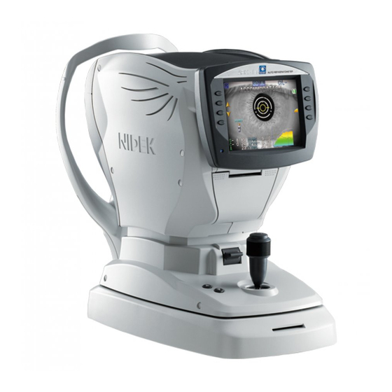
- Page 1 AUTO REF/KERATOMETER AUTO REF/KERATOMETER ARK-1s ARK-1s OPERATOR’S MANUAL OPERATOR’S MANUAL...
- Page 2 Original instructions NIDEK CO., LTD. : 34-14, Maehama, Hiroishi-cho, Gamagori, Aichi 443-0038, Japan (Manufacturer) Telephone: +81-533-67-6611 Facsimile: +81-533-67-6610 NIDEK CO., LTD. : 3F Sumitomo Fudosan Hongo Bldg., 3-22-5, Hongo, (Tokyo Office) Bunkyo-Ku, Tokyo 113-0033, Japan Telephone: +81-3-5844-2641 Facsimile: +81-3-5844-2642 NIDEK INCORPORATED : 47651 Westinghouse Drive, Fremont, California 94539, U.
- Page 3 Before Use This Operator's Manual contains information necessary for the operation of the NIDEK AUTO REF/KERATOMETER ARK-1s. This manual includes operating procedures, safety precautions, specifications, and information about accessories and mainte- nance. This manual is necessary for proper use. Especially, the safety precautions and operating procedures must be thoroughly understood prior to the operation of the device.
-
Page 4: Table Of Contents
Table of Contents 1. SAFETY PRECAUTIONS ....... 1 1.1 For Safe Use - - - - - - - - - - - - - - - - - - - - - - - - - - - - - - - - - - - - - - - - - - - - - - - - - - -1 1.2 Usage Precautions - - - - - - - - - - - - - - - - - - - - - - - - - - - - - - - - - - - - - - - - - - - - - -2... - Page 5 3.11 Measured Value Printing - - - - - - - - - - - - - - - - - - - - - - - - - - - - - - - - - - - - - - - - 61 3.12 Summary Display - - - - - - - - - - - - - - - - - - - - - - - - - - - - - - - - - - - - - - - - - - - - - - 64 3.13 Operation when Peripheral Devices are Connected...
-
Page 7: Safety Precautions
SAFETY PRECAUTIONS For Safe Use BEFORE USE, READ THIS MANUAL. The safety precautions and operating procedures must be thoroughly understood prior to operation of the device. The device complies with ISO 10342 subclause 4: 2010 (Ophthalmic instruments - Eye Refractometers) and ISO 10343 subclause 4: 2009 (Ophthalmic instruments - Ophthalmom- eters). -
Page 8: Usage Precautions
SAFETY PRECAUTIONS: Usage Precautions Usage Precautions Safety of LED CAUTION • The device is a Class 1 LED product and the LED used for the device is safe under expected use conditions including situations such as looking into the LED using an optical system. However, it is recommended to observe the following precautions when using the device: •... - Page 9 SAFETY PRECAUTIONS: Usage Precautions CAUTION • Never use a power strip or extension cable to supply the device with power. The electrical safety may be lowered. • Do not use a power cord other than the one provided. Also do not connect the provided power cord to any other device.
- Page 10 SAFETY PRECAUTIONS: Usage Precautions CAUTION • In the event of smoke or strange odors, immediately turn off the device and disconnect the power plug from the power outlet. After it is certain that the smoke has stopped, contact NIDEK or your authorized distributor.
- Page 11 SAFETY PRECAUTIONS: Usage Precautions After use CAUTION • This device uses a heat-sensitive printer paper. The paper degrades over time and the printed char- acters may become illegible. If glue containing organic solvents or adhesives such as on adhesive tape comes in contact with the printer paper, the printed characters may become illegible. To keep the printed data for a long period of time, make copies of the printouts or write down the mea- sured results by hand.
- Page 12 SAFETY PRECAUTIONS: Usage Precautions Disposal CAUTION • Follow local governing ordinances and recycling plans regarding disposal or recycling of device components, particularly when disposing of the lithium ion battery, circuit board, plastic parts that contain brominated flame retardant, LCD, or power cord. Inappropriate disposal may contaminate the environment.
-
Page 13: Labels And Symbols
SAFETY PRECAUTIONS: Labels and Symbols Labels and Symbols To call attention to users, labels and indications are provided on the device. If labels are peeling off, characters are fading, or otherwise becoming illegible, contact NIDEK or your authorized distributor. Indicates that the operator is advised to refer to the related instructions in the operator’s manual. - Page 14 SAFETY PRECAUTIONS: Labels and Symbols...
-
Page 15: Introduction
2.1.1 Intended use The AUTO REF/KERATOMETER ARK-1s is a medical device which measures objective, subjective refractive errors, and corneal curvature radius of the patient’s eye. This device also offers retroillumi- nation mode for observing the condition of the ocular media, and measures the amplitude of accom- modation. -
Page 16: Configuration And Functions
INTRODUCTION: Configuration and Functions Configuration and Functions 2.2.1 Device configuration 6.5-inch color LCD. Pulling the bottom of the display panel provides an adjustable viewing angle. Function buttons Sets the device and switches the screen. Functions assigned to the function buttons are displayed by ... - Page 17 INTRODUCTION: Configuration and Functions Start button When the start button is pressed, measurement starts regardless of the alignment or focusing condi- tion. Joystick Used for alignment and focusing. (page 23) Eye Care card slot An Eye Care card is inserted here. (page 26) Measuring unit Cover open lever...
- Page 18 INTRODUCTION: Configuration and Functions Chinrest up/down button ( When the chinrest is at the highest (or lowest) mechanical limit, the limit indicator ) is dis- played on the screen. PD window An LED is provided to detect the PD value. CAUTION •...
-
Page 19: Ar/Km Measurement Screen Description
INTRODUCTION: Configuration and Functions 2.2.2 AR/KM measurement screen description The screen for AR (refractive error) and KM (corneal curvature radius) measurements is comprised of three pages. The pages differ only in the function icons displayed to the right of each screen. Patient’s eye (R/L) Function icons The functions assigned to the function buttons on the right and left sides of the screen are displayed... - Page 20 INTRODUCTION: Configuration and Functions Holding down the button for about a second displays the parameter setting Parameter screen. • With the parameter setting, the summary button can be displayed instead of the print button. Pressing the summary button displays the summary screen that shows various mea- ...
- Page 21 INTRODUCTION: Configuration and Functions Auto shot icon Indicates the setting of the auto shot function. Measurement starts automatically as soon as alignment and focusing become optimum. (No icon) Pressing the start button starts measurement. CYL mode Indicates the selected cylinder mode (CYL+, CYL-, CYL±). (page 23) Indication icon An icon indicating the device or measurement status is displayed at the top of the screen.
-
Page 22: Other Measurement Screens
INTRODUCTION: Configuration and Functions 2.2.3 Other measurement screens Various measurements can be performed by switching from the AR/KM measurement screen. Uncorrected visual acuity measurement screen (VA TEST) 0.25 0.32 To conduct the subjective uncorrected visual acuity test 0.63 (page 36) 1.25 Corrected visual acuity measurement screen (SUBJECT) 0.25... - Page 23 INTRODUCTION: Configuration and Functions Sagittal measurement screen (SAGITTAL) To conduct sagittal measurement (page 57)
-
Page 24: Packed Contents
INTRODUCTION: Packed Contents Packed Contents The following are included in the standard configuration. Check the contents before use. Part name Quantity Appearance Printer paper 3 rolls Chinrest paper 1 pack Fixing pins for chinrest paper 2 units Power cord 1 unit Spherical model eye / Contact lens 1 set... -
Page 25: Before First Use
INTRODUCTION: Before First Use Before First Use Place the device on a stable table and connect its power cord. Place the main body on a stable table. Pull the main unit fully to the side to which the device is to be laid down, lock the main unit to the base with the locking lever and lay the device down gently. - Page 26 INTRODUCTION: Before First Use Measurement screen • When the device is used for the first time, the error message “OUT OF PAPER” appears indicating that no paper is loaded. Set the printer paper. (page 75) This completes the setup procedure. ...
-
Page 27: Operating Procedure
OPERATING PROCEDURE Operation Flow Device power ON “3.2 Measurement Method” (page 22) Turn on power to the device and change the parameter settings of the device if necessary. Prepare the patient. Measurement “3.3 AR (refractive error) and KM (corneal curvature radius) Measurements” (page 30) “3.4 Uncorrected Visual Acuity Measurement (UCVA)”... -
Page 28: Measurement Method
OPERATING PROCEDURE: Measurement Method Measurement Method Turn on ( ) the power switch. Wait until the screen switches to the measurement screen. When the device is turned on, the measuring unit makes small forward-backward, side-to-side move- ments for initialization of auto tracking. •... - Page 29 OPERATING PROCEDURE: Measurement Method The measurement items corresponding to the selected measurement mode are displayed on the screen. AR/KM measurement mode AR measurement mode KM measurement mode ● Auto tracking function and auto shot function Activation of auto tracking that automatically achieves alignment in the up-and-down, side-to-side directions and focusing in the forward-backward direction, and auto shot that starts measurement automatically is set by pressing the auto button.
- Page 30 OPERATING PROCEDURE: Measurement Method CYL+ + reading Indicates the cylindrical refractive error by + reading. Indicates the cylindrical refractive error by + reading when the refrac- CYL± Mix reading tive error is positive for any axis angle. Indicates the cylindrical refrac- tive error by - reading in other cases.
- Page 31 OPERATING PROCEDURE: Measurement Method Start AR/KM measurement. Details of AR/KM measurement “3.3 AR (refractive error) and KM (corneal curvature radius) Mea- surements” (page 30) • Instruct the patient not to blink during measurement. Additionally, instruct the patient to blink and open their eyes widely just before measurement to avoid measurement failure.
-
Page 32: Eye Care Card Use
OPERATING PROCEDURE: Measurement Method 3.2.1 Eye Care card use AR-measured data saved on the optional Eye Care card can be transferred to the RT, PC, or such. Data is saved to the Eye Care card at the following times. Eye Care card is inserted before measurement. Saved upon printing. - Page 33 OPERATING PROCEDURE: Measurement Method Remove the Eye Care card. CAUTION • Be careful when handling the Eye Care card so that malfunction does not occur. Be sure not to eject the Eye Care card while it is being accessed (solid yellow display Never bend or damage the card.
-
Page 34: Checking The Measuring Window Cleanliness At Device Start-Up
OPERATING PROCEDURE: Measurement Method 3.2.2 Checking the measuring window cleanliness at device start-up It is possible to set the parameter whether or not to check the cleanliness of the measuring window before measurement. Window check contents at device start-up differ depending on the “61. WINDOW CHECK” parameter setting. -
Page 35: Device Shutdown
OPERATING PROCEDURE: Measurement Method 3.2.3 Device shutdown Normal shutdown To finish measurement, turn off ( ) the power switch. Power may be turned off with any screen displayed. Check the measuring window and clean the window if necessary. (page 96) Clean the forehead rest and chinrest and place the supplied dust cover on the device. -
Page 36: Ar (Refractive Error) And Km (Corneal Curvature Radius) Measurements
OPERATING PROCEDURE: AR (refractive error) and KM (corneal curvature radius) Measurements AR (refractive error) and KM (corneal curvature radius) Mea- surements Perform AR (refractive error) and KM (corneal curvature radius) measurements. The measurement items of the measurement mode (AR/KM measurement, AR measurement, or KM measurement) specified by pressing the R/K button are displayed on the screen. - Page 37 OPERATING PROCEDURE: AR (refractive error) and KM (corneal curvature radius) Measurements ● Focusing indicator display For manual focusing, refer to the focusing indicator ( ) and manipulate the joystick forward and backward for the optimum condition. Too close to the patient’s eye Optimum focusing condition Too far from the patient’s eye •...
- Page 38 OPERATING PROCEDURE: AR (refractive error) and KM (corneal curvature radius) Measurements • When an error or error data appears, the cause may be one of the following. If errors appear again after repeating measurement, check whether: • The patient blinked during measurement. •...
- Page 39 OPERATING PROCEDURE: AR (refractive error) and KM (corneal curvature radius) Measurements ● Full screen display of measurement ring image A thumbnail of the measurement ring image is displayed when AR measurement is complete. If necessary, press the ring image / retroillumination button to switch to the full screen display.
-
Page 40: Error Messages During Ar Or Km Measurement
OPERATING PROCEDURE: AR (refractive error) and KM (corneal curvature radius) Measurements • Instruct the patient to close their eye before starting the next measurement. Let the eye rest to avoid measurement failure by blinking. 3.3.1 Error messages during AR or KM measurement Error messages during AR measurement or KM measurement are displayed in the numeric fields of the measured values. -
Page 41: Cataract Measurement Mode
OPERATING PROCEDURE: AR (refractive error) and KM (corneal curvature radius) Measurements -OVR The corneal curvature radius is too small and not within the mea- (Outside corneal curvature radius negative surable limit. range error) COVR The cylinder value is over the measurable limit. (Outside CYL range error) 3.3.2 Cataract measurement mode... -
Page 42: Uncorrected Visual Acuity Measurement (Ucva)
OPERATING PROCEDURE: Uncorrected Visual Acuity Measurement (UCVA) Uncorrected Visual Acuity Measurement (UCVA) Uncorrected visual acuity measurement can be performed after AR measurement. Hold down the VA button for about a second to display the uncorrected visual acuity measurement screen (VA TEST). A VA chart (VA 0.1 to 1.25) is presented to the patient. - Page 43 OPERATING PROCEDURE: Uncorrected Visual Acuity Measurement (UCVA) Ask the patient whether they can read the pre- 0.25 sented chart. 0.32 0.63 The presented chart is displayed on the screen. 1.25 According to the patient’s response, press the chart 0.25 0.32 button or chart down button to change 0.63...
-
Page 44: Corrected Visual Acuity Measurement (Subjective Refractive Error Measurement)
OPERATING PROCEDURE: Corrected Visual Acuity Measurement (Subjective Refractive Error Measurement) Corrected Visual Acuity Measurement (Subjective Refractive Error Measurement) Subjective refractive error measurement and corrected visual acuity measurement can be performed based on the AR-measured values (or large area measured values For the CYL and AXIS values, AR-measured values (or large area measured values) are used. -
Page 45: Distance Visual Acuity Measurement
OPERATING PROCEDURE: Corrected Visual Acuity Measurement (Subjective Refractive Error Measure- 3.5.1 Distance visual acuity measurement Press the VA button to display the corrected visual acuity measurement screen. The 0.8 VA chart is presented to the patient viewed with the corrective lens 0.25 0.32 selected according to the AR-measured... - Page 46 OPERATING PROCEDURE: Corrected Visual Acuity Measurement (Subjective Refractive Error Measurement) Repeat Steps 3 to 4 to determine the limit of the VA value that the patient can read. To save the VA value lower than 0.1, press the chart up button with the VA chart set to 0.1.
- Page 47 OPERATING PROCEDURE: Corrected Visual Acuity Measurement (Subjective Refractive Error Measure- Perform near visual acuity measurement if necessary. “3.5.2 Near visual acuity measurement” (page 42) Switch the eye to be measured and perform corrected visual acuity measurement for the other eye in the same manner. •...
-
Page 48: Near Visual Acuity Measurement
OPERATING PROCEDURE: Corrected Visual Acuity Measurement (Subjective Refractive Error Measurement) 3.5.2 Near visual acuity measurement Near visual acuity measurement with vision corrected for distance vision, addition power measure- ment required for prescription of glasses for near vision, and visual acuity measurement with addition power can be performed. - Page 49 OPERATING PROCEDURE: Corrected Visual Acuity Measurement (Subjective Refractive Error Measure- To return to the corrected visual acuity measurement screen, press the near button. Press the ADD button to display the addition 0.25 0.32 power measurement screen. 0.63 1.25 The addition power of 1.75 D is added as the default setting. Change the addition power if necessary.
- Page 50 OPERATING PROCEDURE: Corrected Visual Acuity Measurement (Subjective Refractive Error Measurement) Vision comparison function (during near visual acuity measurement) The vision of the near VA chart with the corrected distance values (or corrected near values with addi- tion power) and uncorrected vision (or vision corrected by LM data) are switched to check the vision difference.
-
Page 51: Contrast Visual Acuity / Glare Visual Acuity Measurement
OPERATING PROCEDURE: Corrected Visual Acuity Measurement (Subjective Refractive Error Measure- 3.5.3 Contrast visual acuity / glare visual acuity measurement Reduced visual performance when a low contrast VA chart is viewed or dazzling light is shone to the eye can be checked. Perform distance visual acuity measurement. - Page 52 OPERATING PROCEDURE: Corrected Visual Acuity Measurement (Subjective Refractive Error Measurement) After the contrast visual acuity measurement is complete, press the contrast/glare button to display the glare visual acuity measurement screen. “GLARE:ON” is displayed on the screen and a chart is presented to the patient with the right and left lamps illuminated.
-
Page 53: Retroillumination Image Observation
OPERATING PROCEDURE: Retroillumination Image Observation Retroillumination Image Observation Whether opacity exists on crystalline lenses or vitreous body can be observed. CAUTION • Opacity indexes should be taken as a reference value. When images are captured under the following conditions, actual indexes may not be presented. •... - Page 54 OPERATING PROCEDURE: Retroillumination Image Observation When analysis is complete, the opacity indexes for the center (COI. H, COI. A) and periphery (POI) and a circle indicating the 3 mm range in diameter are displayed. Opacity size within a diameter of 3 mm of COI.
-
Page 55: Accommodation Measurement
OPERATING PROCEDURE: Accommodation Measurement Accommodation Measurement After AR measurement, press the accommodation measurement button to dis- play the accommodation measurement screen (ACCOMMODATION). The initial measurement conditions are “HOME (reference position) = SPH value” and “TPOS (initial position) = SPH value +0.50 D ”... - Page 56 OPERATING PROCEDURE: Accommodation Measurement Press the graph button to display the graph display screen. The detailed graph, accommodation , maximum&minimum AR-measured values, and maximum&minimum pupil size val- ues are displayed. The horizontal axis indicates the elapsed time in one-second increments. Press the graph button to return to the accommodation measurement screen.
-
Page 57: Manual Measurement
OPERATING PROCEDURE: Manual Measurement Manual Measurement The Corneal Size (CS), Pupil Size (PS), and Pupillary Distance (PD) can be manually measured by looking at the eye image. Even if auto measurement is set, manual measurement is possible. • When the CS (Corneal Size) measurement, PS (Pupil Size) measurement, or PD (Pupillary Dis- tance) measurement has been both manually and automatically performed, the manually measured value is used. - Page 58 OPERATING PROCEDURE: Manual Measurement Press the start button to confirm the measurement. A CS value (0.1 mm increments) is displayed in the lower part of the screen. Measure the other eye in the same manner. Switching the eye to be measured displays the Step 1 screen display. To perform PS (Pupil Size) measurement at the same time, press the CS/PS/PD button to switch to the PS measurement screen.
-
Page 59: Ps (Pupil Size) Measurement
OPERATING PROCEDURE: Manual Measurement 3.8.2 PS (Pupil Size) measurement The following is the procedure to measure the Pupil Size (PS). When continuing PS (Pupil Size) mea- surement from CS (Corneal Size) measurement, start from Step 5. • When the mode is switched to PS measurement mode while a still image is displayed on the CS (Corneal Size) measurement screen, the image displayed is still. - Page 60 OPERATING PROCEDURE: Manual Measurement Press the right button or left button to align the guide lines on the pupil of the patient’s eye. The guide line to be aligned is displayed in pink. Press the down button to change the selected guide line. Press the start button to confirm the measurement.
-
Page 61: Pd (Pupillary Distance) Measurement
OPERATING PROCEDURE: Manual Measurement 3.8.3 PD (Pupillary Distance) measurement • In manual PD measurement, five measurements can be saved. The latest PD value is displayed on the measurement screen. The measured PD values (five measurements at the maximum) are printed on the printed results in the order measured. Press the CS/PS/PD button to enter PD mea- surement mode. - Page 62 OPERATING PROCEDURE: Manual Measurement Press the return button to exit from PD mea- surement mode. The screen returns to the measurement screen. The measured PD is displayed on the screen indicating the completion of measurement. • When PD is measured with the “55. NEAR PD PRINT” parameter set to “YES”, the near PD is printed out along with the distance PD.
-
Page 63: Sagittal Measurement
OPERATING PROCEDURE: Sagittal Measurement Sagittal Measurement Set the “81. SAGITTAL” parameter to “YES” in advance. When the “31. PRINT” is set to “AUTO”, reset it to “MANUAL”. As soon as KM-measured values are obtained, the icon is displayed. Press the SAG but- ton to display the sagittal measurement screen. - Page 64 OPERATING PROCEDURE: Sagittal Measurement Press the start button to start measurement. The sagittal radius of the left position is measured. “L” changes to “*” and then “R” starts blinking. • If the measurement is erroneous, “L” changes to “E”. In such cases, press the start button to start measurement again.
- Page 65 OPERATING PROCEDURE: Sagittal Measurement Sample printout The following are sample printouts for the left eye and explanations of each data item. ● Sample printout 1 When the “83. SAGIT PRINT” parameter is set to “ALL” < SAGITTAL > = Sagittal radius on each side SUP.
-
Page 66: 3.10 Contact Lens Measurement
OPERATING PROCEDURE: Contact Lens Measurement 3.10 Contact Lens Measurement To measure hard contact lenses, use the provided contact lens holder. The contact lens holder is incorporated in the spherical model eye. Fill the concave top of the contact lens holder with water. Use a commercial pipette to fill the concave top of the CL holder completely with water. -
Page 67: 3.11 Measured Value Printing
OPERATING PROCEDURE: Measured Value Printing 3.11 Measured Value Printing Measured values are printed out by pressing the print button after measurement. The printing contents can be changed by parameter options “PRINT1” to “PRINT3”. Set the parameters as necessary or desired. “4.5 Device Parameter Settings”... - Page 68 OPERATING PROCEDURE: Measured Value Printing ● Sample printout 2 Patient ID Patient ID scanned by the optional barcode scanner or magnetic card reader Vertex distance Near working distance Corneal refractive index AR-measured values (center) S: Spherical refractive error C: Cylindrical refractive error A: Cylinder axis Confidence index AR median values...
- Page 69 OPERATING PROCEDURE: Measured Value Printing ● Sample printout 3 Uncorrected VA values Subjective refractive error measured values An eye diagram is printed out depending on the “52. EYE PRINT” parameter setting. Corrected distance VA values Contrast VA values Glare VA values Near addition powers, near VA values, WD LM values These are values of the patient’s own glasses measured by a...
-
Page 70: 3.12 Summary Display
OPERATING PROCEDURE: Summary Display 3.12 Summary Display Various measured values can be displayed at the same time on the summary screen. In addition, measured data can be deleted at the measurement item level. To print or export the measured values, press the print button in the summary screen. - Page 71 OPERATING PROCEDURE: Summary Display Prints the measured results. When there is no measured data, long press of the print button Print (for about 1 second) advances the paper. Switches the eye (with the cursor) between the right and left eyes. Right/Left Selects (with the cursor) the upper or lower measurement item.
-
Page 72: 3.13 Operation When Peripheral Devices Are Connected
OPERATING PROCEDURE: Operation when Peripheral Devices are Connected 3.13 Operation when Peripheral Devices are Connected The device can export data to an external device such as the NIDEK motorized refractor and PC. It can also import data from the NIDEK lensmeter. Connecting device Connection port Function... -
Page 73: 3.13.1 Device Connecting Procedure
OPERATING PROCEDURE: Operation when Peripheral Devices are Connected 3.13.1 Device connecting procedure CAUTION • Before connecting a communication cable, be sure to turn off each device. Connecting the cable with the power on may cause malfunction. Connect the cable with the device on its side. Ensure that the plug is inserted into the connector in the proper orientation. -
Page 74: 3.13.2 Operating Procedure
OPERATING PROCEDURE: Operation when Peripheral Devices are Connected 3.13.2 Operating procedure ● Importing data from a lensmeter (LM) (RS-232C connection) ARK-1s parameter setting NIDEK LM parameter setting 73. BAUD-RATE = 9600 Printer = AR print 74. BIT LENGTH = 8 RS-232C = NIDEK 76. - Page 75 OPERATING PROCEDURE: Operation when Peripheral Devices are Connected Place the scanner window over the barcode and press the trigger button. (Barcode scanner) When the barcode has been read successfully, the confirmation LED lights up. Swipe the card with the magnetic card reader. (Mag- netic card reader) A beep sounds and the green LED goes out.
- Page 76 OPERATING PROCEDURE: Operation when Peripheral Devices are Connected...
-
Page 77: Device Settings And Maintenance
DEVICE SETTINGS AND MAINTE- NANCE Troubleshooting Should the device function improperly, attempt to correct the problem according to the following table before contacting NIDEK or your authorized distributor. When Remedy • The power cord may not be correctly connected. Reconnect it securely. - Page 78 DEVICE SETTINGS AND MAINTENANCE: Troubleshooting When Remedy • The auto tracking function or auto shot function may not have been turned on. Turn them on with the auto button. • Room illumination may be reflecting on the cornea. Change the location and try measurement again. •...
-
Page 79: Error Messages And Remedies
DEVICE SETTINGS AND MAINTENANCE: Error Messages and Remedies Error Messages and Remedies If one of the following error codes is displayed on the screen or printed out, follow the suggestions in the cause and remedy column. The error code, detailed indications and serial number of your device are helpful for proper servicing. Error message Cause and remedy •... - Page 80 DEVICE SETTINGS AND MAINTENANCE: Error Messages and Remedies ● Network communication Error message Cause and remedy ERR700 • Error related to Windows file sharing CIFS ERR • ERR703 Error related to the IC board NETWORK ERR IC was damaged by some cause such as electrostatic discharge. •...
-
Page 81: Printer Paper Replacement
DEVICE SETTINGS AND MAINTENANCE: Printer Paper Replacement Printer Paper Replacement When a red line appears along the edge of the printer paper, it means that the paper is running short. In such a case, stop using the printer and replace the printer paper with a new roll. CAUTION •... -
Page 82: Chinrest Paper Attachment
DEVICE SETTINGS AND MAINTENANCE: Chinrest Paper Attachment Chinrest Paper Attachment Remove the two fixing pins from the chinrest. Remove a suitable number of chinrest papers from the pack. An entire pack of chinrest paper cannot be attached. Attach a stack with a thickness of 6 mm of less. Pass the fixing pins through the chinrest paper stack. -
Page 83: Device Parameter Settings
DEVICE SETTINGS AND MAINTENANCE: Device Parameter Settings Device Parameter Settings 4.5.1 Setting parameters Various device parameter settings can be changed in the parameter setting screen (PARAMETER SETTING). Hold down the parameter button for about a second to display the parameter set- ting screen. - Page 84 DEVICE SETTINGS AND MAINTENANCE: Device Parameter Settings Select the desired parameters in the parameter details screen and change the set- ting contents. • The program version of the device is displayed at the bottom right of the parameter setting screen. Parameter details screen operation Returns or advances the screen a single page.
-
Page 85: Parameter Tables
DEVICE SETTINGS AND MAINTENANCE: Device Parameter Settings 4.5.2 Parameter tables • Underlined options indicate factory settings. ● AR (AR measurement) Parameter option Setting contents 1. STEP 0.01D / 0.12D / 0.25D (AR measurement incre- Selects the display increments of SPH or CYL for AR measurement. ments) 2. - Page 86 DEVICE SETTINGS AND MAINTENANCE: Device Parameter Settings ● KM (KM measurement) Parameter option Setting contents 11. KM UNIT mm / D (Display unit of corneal Selects the display unit of the corneal curvature radius from “corneal curvature curvature radius) radius (mm)” or “corneal refractive power (D)”. 12.
- Page 87 DEVICE SETTINGS AND MAINTENANCE: Device Parameter Settings Parameter option Setting contents 40. SUMMARY YES / NO (Summary display) Display of the summary screen When "YES" is selected, the summary button to display the summary screen is displayed instead of the print button.
- Page 88 DEVICE SETTINGS AND MAINTENANCE: Device Parameter Settings 48. PRINT FORMAT R→L / AR→KM / R→L(B) / AR→KM(B) (Print format) R→L: Printing occurs in the order of the right eye (AR value / accommodation value / retroillumination analysis value / subjectively measured value / KM value) and left eye (AR value / accommodation value / retroillumination analysis value / subjectively measured value / KM value).
- Page 89 DEVICE SETTINGS AND MAINTENANCE: Device Parameter Settings ● FUNCTION (Various functions) Parameter option Setting contents 61. WINDOW CHECK YES / NO / DAY (Measuring window Sets whether to automatically check the measuring window for soiling. check function) DAY: The measuring window is checked at the first startup of the day. YES: The measuring window is checked every startup.
- Page 90 DEVICE SETTINGS AND MAINTENANCE: Device Parameter Settings Parameter option Setting contents 72. I/F FORMAT ALL / SHORT (Communication format) Selects the format of data to be transmitted. ALL: All data are transferred. SHORT: Only median values are transferred. 73. BAUD-RATE 9600 / 4800 / 2400 / 1200 (Baudrate) Selects the bit transfer rate for communication.
- Page 91 DEVICE SETTINGS AND MAINTENANCE: Device Parameter Settings ● SUBJECT (Subjective measurement function) Parameter option Setting contents AR(M) / AR(A) / RECALL(M) / RECALL(A) 91. SUBJECT START Selects the screen display in which corrected visual acuity measurement is started. (Corrected visual acuity AR(M): The distance corrected visual acuity measurement screen is displayed measurement screen with button operation.
- Page 92 DEVICE SETTINGS AND MAINTENANCE: Device Parameter Settings ● Chart to be initially displayed (when “AUTO” is selected) The measurement starting chart of uncorrected visual acuity measurement is calculated from AR values. When cylindrical power is contained, -CYL is added to the spherical power. When no AR data is contained, a full VA chart (VA 0.1 to 1.25) is displayed.
- Page 93 DEVICE SETTINGS AND MAINTENANCE: Device Parameter Settings Pressing the change button displays all data including digits other than the set digits. Press- ing the change button again returns to the original display. ● NETWORK 1 (LAN communication function 1) Parameter option Setting contents 111.
- Page 94 DEVICE SETTINGS AND MAINTENANCE: Device Parameter Settings ● NETWORK 2 (LAN communication function 2) Parameter option Setting contents 121. RING IMAGE NO / LOW CONF / YES (Ring image export) Sets whether to export the image data (JPEG) of a ring image when LAN connec- tion is established.
-
Page 95: Setting And Confirming The Network Communication Function (Lan)
DEVICE SETTINGS AND MAINTENANCE: Device Parameter Settings 4.5.3 Setting and confirming the network communication function (LAN) Set the “IP” through “117. FOLDER” parameters necessary for connection to a computer via a net- work (LAN) according to the procedure below. Setting “IP”, “MASK”, “GATE” The input procedure for the “IP”... - Page 96 DEVICE SETTINGS AND MAINTENANCE: Device Parameter Settings Inputting “113. USER” to “117. FOLDER” The input procedure for the “113. USER” parameter is described below. The procedure for the “114. PASSWORD” to “117. FOLDER” parameters is the same. Press the up button or down button to select “113.
- Page 97 DEVICE SETTINGS AND MAINTENANCE: Device Parameter Settings Confirming network communication Confirm that network communication occurs properly. After connecting the device using a LAN cable, make sure that the PC to be connected is turned on. Press the TEST button to check network communica- tion.
-
Page 98: Setting The Date And Time
DEVICE SETTINGS AND MAINTENANCE: Device Parameter Settings 4.5.4 Setting the date and time If the date and time of the printout are incorrect, set the correct date and time. • If the device has not been turned on for about 3 weeks, the date and time may become incorrect. Battery recharging This device uses a rechargeable lithium battery for the date and time display function. -
Page 99: Entering Comments
DEVICE SETTINGS AND MAINTENANCE: Device Parameter Settings 4.5.5 Entering comments Comments to be printed can be changed. (The default setting is “NIDEK ARK-1s”.) Select “COMMENT SET” in the parameter setting screen and press the enter button. The COMMENT SET screen is displayed. -
Page 100: Ar/Km Measurement Accuracy Check
DEVICE SETTINGS AND MAINTENANCE: AR/KM Measurement Accuracy Check AR/KM Measurement Accuracy Check To check the accuracy of measured data, use the provided spherical model eye. The spherical model eye is incorporated with a contact lens holder. Remove the two fixing pins and the stack of chinrest paper from the chinrest. Remove the cap from the spherical model eye and put the model eye on the chinrest with its lens toward the measuring window and then insert the fixing pins. - Page 101 DEVICE SETTINGS AND MAINTENANCE: AR/KM Measurement Accuracy Check ● Values marked on the labels of the spherical model eye VD value Diopter (Unit: D) Corneal curvature radius (Unit: mm) • When the vertex distance is set to a value other than “12.00mm”, set the “2. VERTEX D.” parameter to “12.00mm”...
-
Page 102: Cleaning
DEVICE SETTINGS AND MAINTENANCE: Cleaning Cleaning When the cover or panel of the device becomes dirty, clean it with a soft cloth. For severe stains, soak the cloth in a neutral detergent, wiring well, and wipe. Finally dry with a soft, dry cloth. CAUTION •... -
Page 103: Cleaning The Printer
DEVICE SETTINGS AND MAINTENANCE: Cleaning Check if the window is cleaned using a penlight. If soiled areas remain, clean the window again with new cleaning paper. • When the “61. WINDOW CHECK” parameter is set to “YES” or “DAY”, the measuring window is checked for cleanliness at device start-up. -
Page 104: Consumable List
DEVICE SETTINGS AND MAINTENANCE: Consumable List Consumable List Part name Part number Note Printer paper 80620-00001 Width 58 mm, Length 25 m Chinrest paper 32903-M047 1 pack... -
Page 105: Specifications And Technical Information
SPECIFICATIONS AND TECHNICAL INFORMATION Specifications • Objective refractive error Sphere -30.00 to +25.00 D (VD = 12 mm) (0.01/0.12/0.25 D incre- measurement ments) Cylinder 0 to ±12.00 D (0.01/0.12/0.25 D increments) Axis 0 to 180° (1°/5° increments) Minimum measurable pupil 2 mm in diameter diameter Accuracy: The accuracy specifications are based on the results of eye model testing... - Page 106 SPECIFICATIONS AND TECHNICAL INFORMATION: Specifications • Accommodation mea- 0 to 10.00 D (0.01/0.12/0.25 D increments) surement • Other functions Observation/Display method 6.5-inch color LCD Printer Thermal line printer with auto cutter Interface connectors RS-232C: Two ports USB: One port LAN: One port •...
-
Page 107: Glossary And Abbreviations
SPECIFICATIONS AND TECHNICAL INFORMATION: Glossary and Abbreviations Glossary and Abbreviations The following terms and abbreviations are used in the device and operator's manual. Glossary Term Details AI mode For AR measurement, measurement automatically finishes after the specified number of measurements if the data is stable without variations. If unstable data is included, two additional measurements are taken and then measurement finishes. - Page 108 SPECIFICATIONS AND TECHNICAL INFORMATION: Glossary and Abbreviations Term Details Printing of eye diagram Eye diagram of refractive status of the patient’s eye based on the AR median values (or the latest values when the median values have not been obtained) or the subjective measured values when the subjective measurement has been performed.
-
Page 109: Emc (Electromagnetic Compatibility)
SPECIFICATIONS AND TECHNICAL INFORMATION: EMC (Electromagnetic Compatibility) EMC (Electromagnetic Compatibility) The device complies with the International Electrotechnical Commission standards (IEC 60601-1-2: 2007) for electromagnetic compatibility as listed in the tables below. Follow the guidance in the tables for use of the device in an electromagnetic environment. WARNING •... - Page 110 SPECIFICATIONS AND TECHNICAL INFORMATION: EMC (Electromagnetic Compatibility) Guidance and manufacturer's declaration - electromagnetic emissions The device is intended for use in the electromagnetic environment specified below. The customer or the user of the device should assure that it is used in such an environment. Emissions test Compliance Electromagnetic environment - guidance...
- Page 111 SPECIFICATIONS AND TECHNICAL INFORMATION: EMC (Electromagnetic Compatibility) Guidance and manufacturer's declaration - electromagnetic immunity The device is intended for use in the electromagnetic environment specified below. The customer or the user of the device should assure that it is used in such an environment. Immunity test IEC 60601 test level Compliance level...
- Page 112 SPECIFICATIONS AND TECHNICAL INFORMATION: EMC (Electromagnetic Compatibility)
Need help?
Do you have a question about the ARK-1S and is the answer not in the manual?
Questions and answers
My PD showing error
The error on the PD display of the Nidek Medical ARK-1S indicates a measurement issue. Possible causes include:
- The PD measuring window is blocked.
- The patient blinked during measurement.
- Eyelids or eyelashes are obstructing the measurement.
- The pupil is too small.
- Measurement data exceeds the device’s limit.
To correct, ensure the window is clear, instruct the patient not to blink and to open their eye wider, and let the patient sit in a dark room to enlarge the pupil if needed.
This answer is automatically generated