
Related Manuals for Nidek Medical TONOREF II


Summary of Contents for Nidek Medical TONOREF II
- Page 1 AUTO REF/KERATO/TONOMETER AUTO REF/KERATO/TONOMETER OPERATOR’S MANUAL OPERATOR’S MANUAL...
- Page 2 Original instructions NIDEK CO., LTD. : 34-14, Maehama, Hiroishi-cho, Gamagori, Aichi 443-0038, Japan (Manufacturer) Telephone: +81-533-67-6611 Facsimile: +81-533-67-6610 NIDEK CO., LTD. : 3F Sumitomo Fudosan Hongo Bldg., 3-22-5, Hongo, (Tokyo Office) Bunkyo-Ku, Tokyo 113-0033, Japan Telephone: +81-3-5844-2641 Facsimile: +81-3-5844-2642 NIDEK INCORPORATED : 47651 Westinghouse Drive, Fremont, California 94539, U.
-
Page 3: Safety Precautions
BEFORE USE, READ THIS MANUAL. This operator’s manual contains information necessary for the operation of the NIDEK AUTO REF/KERATO/TONOMETER Model TONOREF II. This manual includes the operating procedures, safety precautions, and specifications. This manual is necessary for proper use. Especially, the safety precautions and operating procedures must be thoroughly understood prior to operation of the device. -
Page 4: Before Use
Usage precautions Safety of LED CAUTION • The device is a Class 1 LED product in accordance with IEC60825-1: 1993+A1: 1997+A2: 2001 and the LED used for the device is safe in expected use conditions including situations such as looking into the LED using an optical system. However, it is recommended to observe the following precautions when using the device: 1)Do not direct LED beams to human eyes when unnecessary. - Page 5 • Install the device in an environment where no contaminants such as corrosive gas, CAUTION acid, or salt are contained in the air. Corrosion or malfunction of the device may result. • Avoid installing the device where it is exposed to direct air-conditioning flow. Changes in temperature may result in condensation inside the device or adversely affect measurements.
-
Page 6: During Use
During Use • Before starting NT measurement, adjust the safety stopper for each patient to prevent WARNING the air nozzle from touching the patient’s eye. Contact between the air nozzle and the eye may damage the cornea. • Before use, perform visual and operation checks. If abnormal conditions are CAUTION encountered, stop using the device. - Page 7 • Before or after use of the device, and before treating each patient, wipe the forehead CAUTION rest and chin rest with a clean cloth such as gauze dampened with rubbing alcohol. If chinrest paper is used, remove one piece for each patient. For severe stains, wipe the area not with a dry cloth but with gauze dampened with alcohol.
- Page 8 • When connecting to peripheral equipment like a PC with LAN connector via a CAUTION medical facility network, insert or connect the isolation transformer between medical electrical equipment and networked device (HUB etc.), or networked device and other electrical equipment. Depending on the types or numbers of other electrical equipment connected to the net- work, electric shock or malfunction/failure of the electrical equipment may occur.
- Page 9 Patient environment The patient environment is the volume of space in which contact can occur between the patient and any part of the device (including connected devices) or between the patient and any other person(s) touching the device (including connected devices). Use devices that comply with IEC60601-1 in the patient environment.
-
Page 10: After Use
After Use • This device uses a heat-sensitive printer paper. The paper degrades over time and the CAUTION printed characters may become illegible. If glue containing organic solvents or adhesives such as on adhesive tape comes in contact with the printer paper, the printed characters may become illegible. To keep the printed data for a long period of time, make copies of the printouts or write the measured results down. -
Page 11: Maintenance And Inspection
Maintenance and inspection • Only service technicians properly trained by NIDEK can repair the device or update CAUTION the software. NIDEK is not responsible for any accidents resulted from improper servicing. • When performing maintenance work, secure sufficient maintenance space. Maintenance work in an insufficient space may result in injury. -
Page 13: Table Of Contents
Table of Contents 1. BEFORE USE ........1 1.1 Outline of the Device . - Page 14 2.8 Parameter Settings ........... . 83 2.8.1 Parameter tables .
- Page 15 4.7 List of Replacement Parts ..........136 5.
-
Page 17: Before Use
BEFORE USE Outline of the Device AUTO REF/KERATO/TONOMETER Model TONOREF II is designed to singly perform objective refraction, corneal shape measurement, and non-contact tonometry measurement by incorporating a standard auto ref/keratometer and non-contact tonometer into one unit. The objective refraction function measures spherical powers, cylindrical powers and cylinder axis. The corneal shape measurement function measures the radius of corneal curvature (corneal refractive powers), the direction of the steepest meridian, and the amount of corneal astigmatism. -
Page 18: Intended Use
BEFORE USE Intended Use Intended Use The AUTO REF/KERATO/TONOMETER TONOREF II is intended to be used for the measurement of the refractive errors of the eye, corneal radius of curvature and intraocular pressure. -
Page 19: Principles
BEFORE USE Principles Principles 1. Objective refraction Fine measurement beams are projected on the fundus of the patient’s eye by a projecting optical system and then computation is performed by capturing the reflected beams as a ring image to measure the refractive errors (SPH, CYL, AXIS) of the patient’s eye. 2. -
Page 20: Device Description
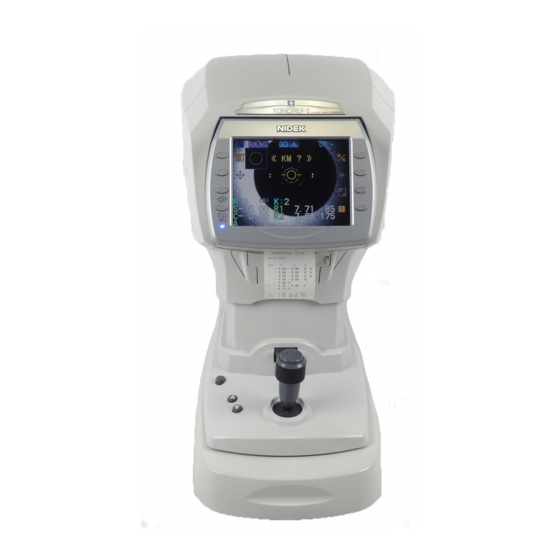
BEFORE USE Device Description Device Description Front view Function buttons LCD screen Memory indicator Start button Joystick Locking lever Power switch Cover open button Printer cover Function buttons Used to set the device and to switch the screen. Functions assigned to the function buttons are displayed by icon next to each switch on the screen. Lower two buttons on the left of the screen have unique functions when the measurement screen is displayed. - Page 21 BEFORE USE Device Description • CLR button ( Used to clear the measured data. When the CLR button is pressed for about a second, all the measured data is erased. • Print button ( When this button is pressed while the memory indicator is lit, measured results are printed out. If this button is pressed when the memory indicator is turned off, the printer paper is fed.
- Page 22 BEFORE USE Device Description Rear view Eyelid detection LEDs Eye level marker Forehead rest LED for Corneal Illumination Chinrest up/down Air nozzle buttons Measuring window Safety stopper Chinrest Patient sensor PD window Forehead rest During measurements, the patient’s forehead should be gently placed over the forehead rest. Clean the forehead rest for each patient.
- Page 23 BEFORE USE Device Description Chinrest up/down buttons ( Move up or down the chinrest. Safety stopper Used to provide a safety space so that the air nozzle does not touch the patient’s eye. Change the position of the stopper for each patient to keep the proper amount of the space for safety. While pressing the safety stopper, “RTN TO ORG”...
-
Page 24: Bottom View
The followings are possible with USB connection. • Barcode or magnetic card reader can be connected to read the patient's ID to the TONOREF II. • USB flash drive can be connected to upgrade the software of the TONOREF II. -
Page 25: Measurement Screen Description
BEFORE USE Measurement Screen Description Measurement Screen Description 1.5.1 R/K measurement screen The screen for the AR (Refractive error) and KM (Corneal curvature radius) measurements has Page 1 and Page 3. The difference between Page 1 and Page 2 lies only in button icons displayed on the right of the screen. - Page 26 Indicates the setting of the auto-tracking function (alignment in the up, down, left, right, back and forth directions and focusing in the back and forth direction). The TONOREF II displays 3D, 2D or Manual (No indication). Auto-tracking in the back-and-forth, side-to-side and up-and-down directions is turned on.
- Page 27 BEFORE USE Measurement Screen Description CYL mode Indicates the selected cylinder mode. R/K button ( Selects a measurement mode in R/K measurement. Select from AR/KM measurement mode, AR measurement mode or KM measurement mode. The selected measurement mode is displayed on the screen. Pressing the button switches the mode in the following order: AR/KM measurement mode (AR and KM continuous measurements) →...
- Page 28 BEFORE USE Measurement Screen Description <When Page 2 is displayed> CS, PS, and PD data, and cataract measurement mode mark are displayed on each page. CAT measurement mode mark CYL mode button PS (Pupil Size) indication CS (Corneal Size) indication CS/PS/PD button Eyeprint button PD (Pupillary Distance) indication...
- Page 29 BEFORE USE Measurement Screen Description Eyeprint button ( Prints the eyeprint view of measured data. The eyeprint is printed out regardless of its parameter setting. See “2.7.2 Eyeprint” (page 81) for details on the eyeprint. PD (Pupillary Distance) indication Displayed when PD (Pupillary Distance) is measured (increments: 1 mm). <When Page 3 is displayed>...
-
Page 30: Nt Measurement Screen
BEFORE USE Measurement Screen Description 1.5.2 NT measurement screen The following is the screen for NT (Tonometry) measurement. <When Page 1 is displayed> Mode mark Auto-tracking mark Applanation area Auto shot mark Patient’s eye ID indication Charge indicator RKT button Measurement range button... - Page 31 BEFORE USE Measurement Screen Description Eyelid detection mode button ( Used to activate the detection (eyelid detection) mode which detects whether the eyelid is over the applanation area or not. Every time the button is pressed, the eyelid detection mode is turned on or off.
-
Page 32: Labels And Indications On The Device
Indicates that the product conforms fully to the requirements of the Medical Device Directive (93/42/EEC). The TONOREF II is classified as a Class IIa according to the Medical Device Directive. Indicates that the product is certified for the US and Canadian markets, to the... - Page 33 BEFORE USE Labels and Indications on the Device For countries other than the USA, Canada, and commonwealth and territories of the USA See “Before Use” (page II) and “1.8 Before First Use” (page 21). [Underside view] See “Before Use” (page II), “During Use” (page IV), and “3 OPERATION WHEN PERIPHERAL DEVICES ARE CONNECTED”...
- Page 34 BEFORE USE Labels and Indications on the Device For the USA and Canada See “Before Use” (page II) and “1.8 Before First Use” (page 21). See “ Before Use” (page II) For Canada For the USA [Underside view] USB-A RS232C See “Before Use”...
- Page 35 BEFORE USE Labels and Indications on the Device For commonwealth and territories of the USA See “Before Use” (page II) and “1.8 Before First Use” (page 21). See “ Before Use” (page II) [Underside view] USB-A RS232C See “Before Use” (page II), “During Use” (page IV), and “3 OPERATION WHEN PERIPHERAL DEVICES ARE CONNECTED”...
-
Page 36: Checking Contents
BEFORE USE Checking Contents Checking Contents Unpack the contents from the shipping carton and check them. The following are included in the standard configuration. • Main body • Printer paper (3 rolls) • Power cable • Pack of chinrest paper •... -
Page 37: Before First Use
BEFORE USE Before First Use Before First Use Place the device on a stable table and connect a power cord to it. • Be sure not to install the device in a location exposed to direct sunlight or a place directly under bright lights. - Page 38 BEFORE USE Before First Use • Connect the power plug to a ground outlet. Or connect a grounding wire to a ground WARNING terminal. Electric shock or fire may occur in the event of device malfunction or power leakage. Turn the power switch on ( The initial screen is displayed on the LCD dis- play and the device starts initializing.
- Page 39 “3.1 Connecting to the NIDEK Motorized Refractor series (RT)” (page 108) “3.2 Connecting to the NIDEK Auto Lensmeter (LM)” Connecting lensmeter and print data with TONOREF II (page 110) Resetting all parameters to their defaults “ Resetting the parameters” (page 85) Setting by parameter Setting parameters allows various functions of the device.
- Page 40 BEFORE USE Before First Use Setting contents Parameters Measurement count of NT measurement 25. NT CONTINUE Whether NT measurement values are displayed in fixed-point 26. DECIMAL DIGIT representation Auto Shot Timing in NT measurement 27. ASHOT TIMING Measurement interval of NT measurement 28.
-
Page 41: Operating Procedure
OPERATING PROCEDURE Operation Flow Turning on the device 2.2 Preparation for Measurement (Page 26) Turn on the device and configure it as necessary. Set up the patient. 2.4 Selecting the Mode (Page 37) Measurement 2.5 AR (refractive error) and KM (corneal curvature radius) Measurements (Page 41) CATARACT measurement mode (Page 50) Measurement ring image display (Page 51) 2.5.2 AR (refractive error) Measurement: AR Measurement Mode (Page 52) -
Page 42: Preparation For Measurement
OPERATING PROCEDURE Preparation for Measurement Preparation for Measurement Turn the power switch on ( Power switch The title screen is displayed and the device is ini- tialized. Wait for a while until the screen switches to the measurement screen. When the power is turned on, the main body makes small side-to-side and back-and-forth movements in order to determine the initial posi- tion for auto-tracking;... - Page 43 OPERATING PROCEDURE Preparation for Measurement The measurement screen is displayed. The measurement screen with the measure- ment mode (R/K or NT measurement) selected just before the last shutdown is displayed. R/K measurement screen NT measurement screen • “NO PAPER” is displayed on the screen if the power switch is turned on with no printer paper loaded.
- Page 44 OPERATING PROCEDURE Preparation for Measurement See "2.8 Parameter Settings (page 83)" for details. 3: CYL mode Cylinder mode, the reading direction of cylinder data in which CYL data (cylindrical power) is repre- sented during the measurement is selected by pressing the CYL mode button Screen CYL mode Description...
- Page 45 (or lower limit mark ) is displayed on the screen. Limit mark • When the TONOREF II displays a thumbnail in the R/K measurement, the limit mark ( ) is covered and cannot be seen. Perform the selected measurement. For the contents of each measurement, see: "2.5 AR (refractive error) and KM (corneal curvature radius) Measurements (page 41)"...
- Page 46 OPERATING PROCEDURE Preparation for Measurement • Instruct the patient not to blink during measurement. Additionally, instruct the patient not to blink and open his/her eyes immediately before measurement to avoid measurement failure. • Instruct the patient to open both eyes wide during measurement. Closing one eye may cause an unstable fixation and the other eye will not open wide.
-
Page 47: Measuring Window Check For Soiling And Puffed Air Pressure Check During Startup
OPERATING PROCEDURE Preparation for Measurement 2.2.1 Measuring window check for soiling and puffed air pressure check during startup It is possible to parameter-set whether or not to check the measuring window for soiling and the pressure of puffed air before measurements. Parameter name Description Selection of whether or not to automatically check the measuring... - Page 48 • If one of the following messages is displayed: After the completion of all the checks, put the TONOREF II into NT measurement mode, turn the device off once and check the air nozzle for soiling. If the air nozzle is soiled, wipe it clean of soling.
-
Page 49: Switching Between R/K Measurement And Nt Measurement
OPERATING PROCEDURE Preparation for Measurement 2.2.2 Switching between R/K measurement and NT measurement When the measurement mode is switched from R/K measurement to NT measurement, the measuring unit inside the main body is switched. To switch the measuring unit, pull the main body fully toward the operator for safety. - Page 50 OPERATING PROCEDURE Preparation for Measurement • In RKT mode, it is possible to select the method of switching the measuring unit by setting the “72. CHANGE MODE” parameter. When the parameter is set to AUTO, pull the main body toward operator according to the “PULL BACK”...
-
Page 51: Finishing The Measurements
OPERATING PROCEDURE Finishing the Measurements Finishing the Measurements 2.3.1 Normal shutoff Turn off ( ) the power switch. It is allowed to turn off the power with any screen displayed. To exit measurements, inspect the measuring unit, air nozzle etc. for soiling and clean them. -
Page 52: Shutoff Before Transporting The Device
OPERATING PROCEDURE Finishing the Measurements 2.3.2 Shutoff before transporting the device Before the device is transported, put the device in packing mode. In packing mode, the measuring unit and chinrest are automatically set in preparation for transportation. Inspect the measuring unit, air nozzle etc. for soiling and clean them. See "4.6 Cleaning (page 132)". -
Page 53: Selecting The Mode
OPERATING PROCEDURE Selecting the Mode Selecting the Mode Select the measurement mode from the following options: Mode mark Auto-tracking/auto shot ON mark RKT button R/K button Auto button R/K measured data Measurement items Select the measurements from R/K (Refractive error/corneal curvature radius) measurement and NT (tonometry) measurement. - Page 54 OPERATING PROCEDURE Selecting the Mode AR/KM measurement mode is selected by default; there is no need to select when proceed- ing to measurements in AR/KM measurement mode. The items corresponding to the selected measurement mode are displayed on the screen. AR/KM measurement mode AR measurement mode KM measurement mode...
-
Page 55: Switching To Manual Mode
OPERATING PROCEDURE Selecting the Mode 2.4.1 Switching to manual mode By pressing the manual mode button during measurements, it is possible to turn off both the auto-tracking and auto shot functions (manual mode). Press the manual mode button to turn off the auto-tracking function according to the state the patient’s eye after starting the measurement with the auto-tracking function on. -
Page 56: Sleep Mode
OPERATING PROCEDURE Selecting the Mode 2.4.2 Sleep mode The device goes into sleep mode automatically to save power if no button have been pressed for a certain period of time. The time that the device goes into sleep mode can be selected from 5 minutes, 10 minutes, 15 minutes, or NO (no sleep mode) with the 64. -
Page 57: Ar (Refractive Error) And Km (Corneal Curvature Radius) Measurements
OPERATING PROCEDURE AR (refractive error) and KM (corneal curvature radius) Measurements AR (refractive error) and KM (corneal curvature radius) Measurements In R/K mode, three types of the measurement modes are selectable according to measurement items. Measurement item Description AR (refractive error) and KM (corneal curvature radius) measurements take place AR/KM measurement mode in a row. -
Page 58: Ar/Km Measurement Mode
OPERATING PROCEDURE AR (refractive error) and KM (corneal curvature radius) Measurements 2.5.1 AR (refractive error) and KM (corneal curvature radius) measurements: AR/KM measurement mode In AR/KM measurement mode, AR measurement and KM measurements take place in a row. When AR/KM measurement mode is selected, refractive errors (S, C and A) and corneal curvature radius (R1, R2) are displayed on the screen. - Page 59 OPERATING PROCEDURE AR (refractive error) and KM (corneal curvature radius) Measurements Manipulate the joystick to display the patient’s eye on the screen. By pulling the joystick backward, pushing it forward, tilting it to the left and right, the main body moves back, forth, to the right, and to the left.
- Page 60 OPERATING PROCEDURE AR (refractive error) and KM (corneal curvature radius) Measurements 3D auto-tracking 1) Perform rough alignment and focusing by Up-and-down and side-to-side alignment: Auto manipulating the joystick to place in the working range of auto-tracking. 2) When the device is placed within the working range of auto-tracking, it automat- ically starts alignment and focusing.
- Page 61 OPERATING PROCEDURE AR (refractive error) and KM (corneal curvature radius) Measurements When the main body is not within the working range of auto-tracking: As the limit mark is displayed, manipulate the joystick or chinrest up/down button in the direction of the arrows.
- Page 62 OPERATING PROCEDURE AR (refractive error) and KM (corneal curvature radius) Measurements Measurement starts. Measurements take place automatically when the device is best aligned and focused on the eye (when the auto shot function is turned on). * When the auto shot function is turned off, press the start button to start measurement. •...
- Page 63 OPERATING PROCEDURE AR (refractive error) and KM (corneal curvature radius) Measurements • If the device gets out of alignment and focus during measurement, the measurement is interrupted. If the measurement is retried, the measured results are added to the former results and stored.
- Page 64 OPERATING PROCEDURE AR (refractive error) and KM (corneal curvature radius) Measurements The corneal curvature radius is too small and beyond the -OVR (Negative corneal curvature range over error) measurable limit. COVR The cylindrical power is over the measurable limit. (CYL range over error) Measurement completes.
- Page 65 OPERATING PROCEDURE AR (refractive error) and KM (corneal curvature radius) Measurements Measure the other eye in the same manner. When the other eye is set in front of the measur- ing unit, the measuring unit returns to the origin in the back-and-forth and side-to-side directions. When measuring a single eye only, perform NT measurement.
- Page 66 OPERATING PROCEDURE AR (refractive error) and KM (corneal curvature radius) Measurements CATARACT measurement mode If cataract or abnormal eyes cannot be measured during AR (refractive error) measurement, cataract measurement mode turns on automatically. In cataract measurement mode, measurement conditions are changed so as to enhance ease of mea- surements of even cataract or abnormal eyes.
- Page 67 OPERATING PROCEDURE AR (refractive error) and KM (corneal curvature radius) Measurements Measurement ring image display The TONOREF II projects measurement beams on the patient’s fundus and computation is performed by capturing the reflected beams as a ring image to measure the refractive errors of the patient’s eye.
-
Page 68: Ar (Refractive Error) Measurement: Ar Measurement Mode
OPERATING PROCEDURE AR (refractive error) and KM (corneal curvature radius) Measurements AR (refractive error) Measurement: AR Measurement Mode 2.5.2 Perform AR measurement in the same manner as AR/KM measurement mode. KM (corneal curvature radius) measurement is not performed; KM-measured data is not displayed on the screen. - Page 69 OPERATING PROCEDURE AR (refractive error) and KM (corneal curvature radius) Measurements • If the device gets out of alignment and focus during measurement, the measurement is interrupted. If the measurement is retried, the measured results are added to the former results and stored.
-
Page 70: Km (Corneal Curvature Radius) Measurement: Km Measurement Mode
OPERATING PROCEDURE AR (refractive error) and KM (corneal curvature radius) Measurements KM (corneal curvature radius) Measurement: 2.5.3 KM Measurement Mode Perform KM measurement in the same manner as AR/KM measurement mode. AR (refractive error) measurement is not performed; AR-measured data is not displayed on the screen K: KM measurement count R1: Corneal curvature radius and corneal cylinder axis angle of flattest meridian... - Page 71 OPERATING PROCEDURE AR (refractive error) and KM (corneal curvature radius) Measurements <KM measurement error messages> Error messages are the same as those for <KM measurement error messages> of AR/KM measurement mode. See "2.5.1 AR (refractive error) and KM (corneal curvature radius) measurements: AR/KM mea- surement mode (page 42)"...
-
Page 72: 2.5.4 Cs (Corneal Size) Measurement
OPERATING PROCEDURE AR (refractive error) and KM (corneal curvature radius) Measurements 2.5.4 CS (Corneal Size) Measurement Press the CS/PS/PD button to enter CS measurement mode. “<<CORNEAL SIZE>>”, guide lines and “START SW: CAPTURE” are displayed on the screen. Pressing the CS/PS/PD button switches the mode in the following order: CS→... - Page 73 OPERATING PROCEDURE AR (refractive error) and KM (corneal curvature radius) Measurements Press the right button or left button to align the guide line with the left end of the patient’s cornea. Move the guide line to the left end of the pa- tient’s cornea.
- Page 74 OPERATING PROCEDURE AR (refractive error) and KM (corneal curvature radius) Measurements Press the exit button to exit from CS measurement. The screen returns to the measurement screen. The CS-measured data is displayed on the screen, indicating the completion of CS mea- surement.
-
Page 75: Ps (Pupil Size) Measurement
OPERATING PROCEDURE AR (refractive error) and KM (corneal curvature radius) Measurements PS (Pupil Size) Measurement 2.5.5 This is the procedure to measure the pupil size (PS). To measure PS continuing from CS (Corneal Size) measurement, start from Step 5. • If the mode is switched to PS measurement mode from when a still image is displayed on the CS (Corneal SIze) measurement screen, a still image is displayed. - Page 76 OPERATING PROCEDURE AR (refractive error) and KM (corneal curvature radius) Measurements • When the right button or left button has never been pressed, the measured values are not displayed. Start measurement again from capturing. Press the right button or left button to align the guide line on the right of the patient’s pupil.
- Page 77 OPERATING PROCEDURE AR (refractive error) and KM (corneal curvature radius) Measurements Press the exit button to exit from PS mea- surement. The screen returns to the measurement screen. The PS-measured data is displayed on the screen, indicating the completion of PS mea- surement.
-
Page 78: 2.5.6 Pd (Pupillary Distance) Measurement
OPERATING PROCEDURE AR (refractive error) and KM (corneal curvature radius) Measurements 2.5.6 PD (Pupillary Distance) Measurement Auto-PD measurement When the 63. AUTO PD parameter is set to YES, at the moment where measurement of both eyes is completed, PD measurement is also completed and then the PD value is displayed. - Page 79 OPERATING PROCEDURE AR (refractive error) and KM (corneal curvature radius) Measurements After proper alignment of the right eye and left eye, press the Start button each time. Auto-tracking and auto focusing function are turned off automatically, however when in the PD measurement mode, the focusing indicator is displayed.
-
Page 80: 2.5.7 Measuring Hard Contact Lenses
OPERATING PROCEDURE AR (refractive error) and KM (corneal curvature radius) Measurements 2.5.7 Measuring Hard Contact Lenses To measure hard contact lenses, use the provided CL holder. The contact lens holder is incorporated in the spherical model eye. The CL holder is integral with the spherical model eye. Fill the concave top of the CL holder with water Pipette... - Page 81 OPERATING PROCEDURE AR (refractive error) and KM (corneal curvature radius) Measurements Place the model eye/CL holder with the surface of the contact lens to be measured facing toward the measuring window and insert the fixing pins. Select the KM measurement mode and measure the lens in the same manner as KM measurement.
-
Page 82: Nt (Tonometry) Measurement: Nt Mode
OPERATING PROCEDURE NT (Tonometry) Measurement: NT Mode NT (Tonometry) Measurement: NT Mode During NT measurement, the types of the target and focusing indicator are parameter (74. TARGET TYPE) -selectable from two options: During the R/K and NT measurements, the same target and focusing indicator are displayed (Factory setting). - Page 83 OPERATING PROCEDURE NT (Tonometry) Measurement: NT Mode If necessary, disable the eyelid detection mode Disable the mode by pressing the eyelid detec- tion mode button For the details of the eyelid detection mode, see "2.6.1 Eyelid detection mode (page 77)". Eyelid detection mode marker Set the safety space between the patient’s eye and air nozzle with the safety stopper.
- Page 84 OPERATING PROCEDURE NT (Tonometry) Measurement: NT Mode Provide the patient with an explanation about the measurement. To help the patient relax, provide the patient with such an explanation before starting the measurement as: “You may be surprised by air puffed into your eye, but do not worry. Please be patient and relax for a moment until I can measure your intraocular pressure three times per eye.”...
- Page 85 OPERATING PROCEDURE NT (Tonometry) Measurement: NT Mode Perform alignment and focusing. The methods of alignment and focusing vary Focusing indicator according to the 26. TRACKING SW parameter setting. * See “ Auto-tracking mode and auto shot mode” (Page 38) for details. Align the alignment spot reflected over the patient’s eye with the target ( Perform focusing according to the indication of...
- Page 86 OPERATING PROCEDURE NT (Tonometry) Measurement: NT Mode 3) As the focusing indicator is displayed, manipulate the joystick until the optimal focusing indicator is displayed. When the auto-tracking function is turned off: 1) Manipulate the joystick to move the align- Up-and-down and side-to-side alignment: ment spot reflected by the patient’s eye Manual within the alignment target.
- Page 87 OPERATING PROCEDURE NT (Tonometry) Measurement: NT Mode Indication of the focusing indicator: If the main body gets out of the working range of auto-tracking in the back-and-forth direc- tion, the limit mark is displayed. Manipulate the joystick in accordance with the indication of the focusing indicator.
- Page 88 OPERATING PROCEDURE NT (Tonometry) Measurement: NT Mode Start the measurement. • When the auto shot function is on: The measurement takes place automatically when the device is best aligned and focuses on the eye. • The operator can start the measurement by pressing the start button. Press the start button to start the measurement when it takes some time until the measurement takes place for patients who often blink.
- Page 89 OPERATING PROCEDURE NT (Tonometry) Measurement: NT Mode <Error messages during NT measurement> Error message Description Alignment is not proper. (Alignment error) Perform the alignment and the measurement again. As the eye was not opened enough, corneal applanation was insufficient. Instruct the patient to open his or her eyes wider. (Applanation error) If the patient cannot do so, ask an assistant to open the eyelids wider by using a swab, etc.
- Page 90 OPERATING PROCEDURE NT (Tonometry) Measurement: NT Mode If the “CHECK THE EYE” error occurs: Check the condition of the patient’s eye. If the patient cannot open the eye wide or eyelashes are over the applanation area, you have to help the patient open the eye wide. For a watery eye, have the patient blink his or her eyes, or wipe the tears.
- Page 91 OPERATING PROCEDURE NT (Tonometry) Measurement: NT Mode Measurement completes. • When NT AI mode is YES: When the specified number of NT measurements is performed and the data is stable (no varia- *2*3 tions), the measurement automatically completes. Indications in the screen after the measurement: “<<FINISH>>”...
- Page 92 OPERATING PROCEDURE NT (Tonometry) Measurement: NT Mode Inform the patient of the completion of the measurement and instruct him or her to take a comfortable position. Print the measured results. Printing operation varies according to the “31. PRINT” parameter setting. 31.
-
Page 93: Eyelid Detection Mode
OPERATING PROCEDURE NT (Tonometry) Measurement: NT Mode 2.6.1 Eyelid detection mode With this mode, the device always checks the eye for the amount of eye-opening and the measure- ment takes place automatically only when the eyelid is opened wide. Activating and cancelling eyelid detection mode Press the eyelid detection mode button to activate or cancel the mode. -
Page 94: Printing
OPERATING PROCEDURE Printing Printing 2.7.1 Printing measured data Measured data is printed out by pressing the print button after measurement. Printing completes with paper still attached so that it does not fall. Tear off the paper to detach. • When the 31. PRINT parameter is set to AUTO, printing starts automatically when the measurements of both eyes complete. - Page 95 OPERATING PROCEDURE Printing <Sample printout 2> Patient No. Space for name and sex Date and time of measurement Vertex distance*1 Near working distance*2 Corneal refractive index AR measurement, Confidence index*3 S = Spherical powers C = Cylindrical powers A = Cylinder axis AR median values*4 SE value*5 Eyeprint*6...
- Page 96 OPERATING PROCEDURE Printing Near working distance Used for near PD calculation. Changeable in the 35 to 70 cm or in the 14- to 28-inch range by the corresponding parameter. Confidence index One of six confidence indexes (9, 8, 7, 6, 5 or E) is printed out. E is erroneous data. The higher the confidence index, the higher the reliability of measured data.
-
Page 97: Eyeprint
OPERATING PROCEDURE Printing 2.7.2 Eyeprint Aside from normal printing, the eyeprint button serves to print the eyeprint and PD value only based on the AR median values or latest values. The eyeprint is printed out regardless of the 52. EYE PRINT parameter. -
Page 98: Printing Parameter Settings
OPERATING PROCEDURE Printing 2.7.3 Printing parameter settings The present parameter settings, set time, comments and maintenance program versions are printed out. Press the parameter button for about a second. The PARAMETER SETTING screen is displayed. The parameter No. and parameter names are displayed. -
Page 99: Parameter Settings
OPERATING PROCEDURE Parameter Settings Parameter Settings The TONOREF II is provided with parameters that set various functions according to the user’s usage pattern. The procedure for checking and changing the parameter settings is explained. Press the parameter button for about a second. - Page 100 OPERATING PROCEDURE Parameter Settings Press the execute button to switch to the [PRINT1] screen. Parameters and their settings are displayed. A parameter that is being selected is highlighted. PRINT1 screen Press the up/down button to select a parame- ter to be changed. Move the highlight.
- Page 101 OPERATING PROCEDURE Parameter Settings To change the page of parameter: Page up button Displays the previous page. Page down button Displays the next page. Repeat Steps 4 to 5 to change the desired parameter settings. To finish setting the parameters, press the exit button The screen returns to the step1 PARAMETER SETTING screen To finish setting the parameters, press the exit button...
-
Page 102: Parameter Tables
OPERATING PROCEDURE Parameter Settings 2.8.1 Parameter tables [AR (AR measurement)] * Underlined options indicate factory settings. Parameter Settings STEP 0.01D / 0.12D / 0.25D VERTEX D. 0.00mm / 10.50mm / 12.00mm / 13.75mm / 15.00mm / 16.50mm AXIS STEP 1°/ 5 MEAS MODE CON. - Page 103 OPERATING PROCEDURE Parameter Settings 7 : AR THUMBNAIL Selects whether or not to display the thumbnail screen of the measurement ring image during AR measure- ment. When YES is selected, a thumbnail of the measurement ring image is displayed to the left of the screen after AR measurement is complete.
- Page 104 OPERATING PROCEDURE Parameter Settings 21 : SET LOW CONF (Display of low confidence data) Selection of whether or not to display low confidence data. 22 : LOW CONF LV (Display of confidence level) Setting of how to express the level of low confidence data when the 21. SET LOW CONF parameter is set to YES.
- Page 105 OPERATING PROCEDURE Parameter Settings • The number of required NT measurement data sets can be specified with the “25. NT CONTINUE” parameter. 30 : DELETE SELECT (Selection of the NT measurement data deletion method) When the number of measurements exceed the specified amount, the existing data sets TIME are deleted in chronological order, beginning from the oldest.
- Page 106 OPERATING PROCEDURE Parameter Settings 38 : DATE FORMAT (date format) Selects the format of date. Y/M/D Year, Month, Date M/D/Y Month, Date, Year D/M/Y Date, Month, Year No printing 39 : PRINT COMMENT Selects whether or not to print comments. [PRINT2 (Print setting 2)] * Underlined options indicate factory settings.
- Page 107 OPERATING PROCEDURE Parameter Settings 44 : ERROR DATA Selects whether or not to display and print erroneous data obtained during AR measurement. When this parameter is set to YES and the measured data is erroneous, the data is displayed in yellow and “Err”...
- Page 108 OPERATING PROCEDURE Parameter Settings [PRINT3 (Print setting 3)] * Underlined options indicate factory settings. Parameter Settings SE PRINT YES / NO EYE PRINT YES / NO TL PRINT YES / NO CL PRINT YES / NO NEAR PD PRINT YES / NO 35 to 70 cm (5 cm increments) WORKING D.
- Page 109 OPERATING PROCEDURE Parameter Settings [FUNCTION 1 (Various functions 1)] * Underlined options indicate factory settings Parameter Settings WINDOW CHECK YES / NO / DAY TRACKING SW TRC/ASHOT / ASHOT ON / ASHOT OFF AUTO PD YES / NO SLEEP 5MIN / 10MIN / 15MIN / NO BEEP LOW / HIGH / NO AR BRIGHTNESS...
- Page 110 OPERATING PROCEDURE Parameter Settings 64 : SLEEP (sleep time) Selects the auto-sleep function. The LCD is shut down automatically after a set period during which no buttons have been pressed. Select the time period from 5 (min.), 10 (min.), 15 (min.) or NO. 65 : BEEP (beep sound) Sets the pitch of the beep sound (electronic beeper sound) that is produced during measurement.
- Page 111 OPERATING PROCEDURE Parameter Settings 71 : PRESSURE CHECK (Automatic checking of air pressure) Selection of whether or not to automatically check the air pressure. The pressure of puffed air is automatically checked during startup and the check result is displayed. If the pressure of the puffed air is abnormal, a message is printed out.
- Page 112 Selects whether or not to print the data imported from the lensmeter connected to the data input port by the built-in printer of the TONOREF II. When the parameter is set to YES, the data is printed from the TONOREF II printer by pressing the print but- ton of the lensmeter.
- Page 113 OPERATING PROCEDURE Parameter Settings 91 : READER START (Position to start reading) Sets the position to start reading. 92 : READER LENGTH (Length of reading) Sets the length of the data to be read. In the ID field, when read after setting is checked, the read result of set conditions is displayed.
-
Page 114: Setting Network Function
• Before connecting the network, obtain the following information from the network administrator of the facility. 1. DHCP can be set to on. 2. TCP/IP: IP address and subnet mask of the TONOREF II Default gateway (only when necessary) 3. File sharing of the computer: User name, password, and domain 4. - Page 115 * When the TEST button on the lower left in the NETWORK screen is pressed, whether or not the LAN interface cable is connected to the TONOREF II is checked. A message is displayed for two seconds with a beep sound.
- Page 116 OPERATING PROCEDURE Parameter Settings : IP Input the IP address. The input procedure is as follows. Press to select "IP". The screen is as shown to the right. 2) Press the execute button The screen changes to the IP address input screen.
- Page 117 OPERATING PROCEDURE Parameter Settings : MASK Input subnet mask. The input procedure is same as "IP". Refer to above "IP". * When "102. DHCP" is set to YES, subnet mask is displayed as "0. 0. 0. 0" and cannot be selected. To enable the setting, return to the measurement screen, then restart the device.
- Page 118 OPERATING PROCEDURE Parameter Settings Moves the cursor in the input field to right. Press Press or press the start Determines the character to be entered and moves the highlight to the next digit. button Erases the character at the cursor position and Press moves the highlight to the previous digit.
-
Page 119: Setting The Date And Time
OPERATING PROCEDURE Parameter Settings 2.8.3 Setting the date and time When the date and time of the printout is not correct, set the correct date and time. • If the device is not turned on for three weeks, the date and time may be shifted. Press the parameter button for about a second. - Page 120 OPERATING PROCEDURE Parameter Settings Press the up button or down button to move the highlight to an item to be changed. Press the right button or the left button to change the setting. Increases the number. Right button Decreases the number. Left button To change the time format: Change the time format between the 24-hour and 12-hour.
-
Page 121: Entering Comments
OPERATING PROCEDURE Parameter Settings 2.8.4 Entering comments Comments to be printed can be changed (factory setting: “NIDEK TONOREF II”). Press the parameter button for about a second. The PARAMETER SETTING screen is dis- played. Press the down button to select the COM- MENT SET parameter. - Page 122 Press the exit button to return to the measurement screen. The entered comments are saved. • When the start button is held down with the SET COMMENT screen displayed, comments return to the default setting (“NIDEK TONOREF II”).
-
Page 123: Operation When Peripheral Devices Are Connected
RT), computer, and Eye Care card system. The TONOREF II also imports data from the NIDEK lensmeter (hereafter referred to as the LM) or reads patient's ID data by a USB-connected barcode or magnetic card reader. -
Page 124: Connecting To The Nidek Motorized Refractor (Rt)
OPERATION WHEN PERIPHERAL DEVICES ARE CONNECTED Connecting to the NIDEK Motorized Refractor (RT) Connecting to the NIDEK Motorized Refractor (RT) 3.1.1 Outline Any data on printout can be exported to the RT. The AR-measured data transmitted to the RT is used as objective data in subjective tests. Connectable devices: RT-2100 series, RT-5100 Data transmitted to a computer can be managed by various database software. -
Page 125: Connecting Procedure
) of the TONOREF II via an interface cable (optional). Connect the cable with the device laid down. Attach a ferrite core (optional) to the interface cable connector of the TONOREF II. Ferrite core (optional) RS-232C cable (optional) To RT 3.1.3... -
Page 126: Connecting To The Nidek Auto Lensmeter (Lm)
(optional). Connect the cable with the device laid down. Attach a ferrite core (optional) to the interface cable connector of the TONOREF II. Connect the data output port ( ) of the TONOREF II to the RT via an interface cable (optional). -
Page 127: Operating Procedure
Operating procedure After lens measurement with the LM, press the print button on the LM. The TONOREF II receives lensmeter readings from the LM. • When the device communicates with the LM, set the communication parameters of each instrument as follows. See the operator’s manual for the setting method of each device. -
Page 128: Connecting To Computer
OPERATION WHEN PERIPHERAL DEVICES ARE CONNECTED Connecting to Computer Connecting to Computer 3.3.1 Outline Any data on printout can be exported to a computer. The measured data exported to a computer can be managed by various database software. There are two ways for connection, RS-232C connection and LAN connection. Manage with database software Measured data Computer... -
Page 129: Rs-232C Connection
) on the bottom of the TONOREF II via an interface cable (optional). Connect the cable with the device laid down. Attach a ferrite core (optional) to the interface cable connector of the TONOREF II. Ferrite core (optional) RS-232C cable (optional) -
Page 130: Network Connection (Lan)
3.3.3 Network connection (LAN) Connecting procedure Connect a computer to the LAN port on the bottom of the TONOREF II via a LAN cable. Connect the cable with the device laid down. Connect the other end of the LAN cable to the HUB connected to the receiver PC. - Page 131 NT Mode” (page 66) for the measuring method. See “2.7 Printing” (page 78) for printing. The TONOREF II automatically transmits data to the computer. The measured data is printed. • When “31.PRINT” parameter is set to “NO”, error No. and measurement data is printed...
-
Page 132: Connecting To The Eye Care Card System
“ON” position. In the case of AUTO OPTOMETRY SYSTEM COS-550: Objectively measured data EyeCa-RW Eye Care card EyeCa-RW TONOREF II 3.4.2 Method of connection Connect the interface cable of the EyeCa-RW to the data output port ( Interface cable (optional) -
Page 133: Transferring Data With The Eyeca-Rw
The EyeCa-RW emits a short beep and the access indicator illuminates in green. If the TONOREF II has not measured data in its memory, the memory indicator of the TONOREF II is shut off. -
Page 134: Erasing Data On The Eye Care Card
OPERATION WHEN PERIPHERAL DEVICES ARE CONNECTED Connecting to the Eye Care Card System When not printing measured data Set the 31. PRINT parameter to “MANUAL” or “NO” in advance. See “2.8 Parameter Settings” (page 83) for details. After measurements, insert the Eye Care card. The EyeCa-RW emits a short beep and the access indicator illuminates in green. -
Page 135: Connecting Barcode / Magnetic Card Reader
3.5.1 Outline By connecting the optional barcode reader or magnetic card reader to the TONOREF II via USB, the patient ID can be read to the TONOREF II. • The patient ID can be read before and after measurement but must be performed before printing. - Page 136 OPERATION WHEN PERIPHERAL DEVICES ARE CONNECTED Connecting Barcode / Magnetic Card Reader...
-
Page 137: Maintenance
MAINTENANCE Troubleshooting In the event that the device does not work correctly, correct the problem according to the following table before contacting NIDEK or your authorized distributor. Symptom Remedy • The power cord may not be correctly connected. The LCD display does not turn on. Reconnect it securely. - Page 138 MAINTENANCE Troubleshooting Symptom Remedy • The auto-tracking function or auto shot function may not have been turned on. Turn them on with the auto button • Room illumination may be reflecting on the cornea. Change the location and try measurement again. •...
-
Page 139: Error Messages And Countermeasures
MAINTENANCE Error Messages and Countermeasures Error Messages and Countermeasures If one of the following error codes is displayed on the screen or printed out, follow the suggestions in the cause and countermeasure column. The error code, detailed indications and serial number of your device are helpful in proper servicing. Error code Cause and countermeasure •... - Page 140 MAINTENANCE Error Messages and Countermeasures Error code Cause and countermeasure • Error related to control signals for communication (input port) ERR021 Ensure that the interface cable is properly connected to the input port. • Also ensure that the communication parameters are properly set. •...
- Page 141 MAINTENANCE Error Messages and Countermeasures Error code Cause and countermeasure • Error related to the shutter on the air nozzle part. A malfunction of the shutter driving motor, shutter sensor, electric circuit board, or a break in a ERR051 cable is probable. •...
- Page 142 MAINTENANCE Error Messages and Countermeasures Error code Cause and countermeasure ERR700 • Error related to Windows file sharing • Error related to IC IC was damaged by any cause such as electrostatic discharge. ERR703 • If the same error code is displayed even after the device is turned on again, turn off power to the device and contact NIDEK or your authorized distributor.
-
Page 143: Replacing Printer Paper
MAINTENANCE Replacing Printer Paper Replacing Printer Paper When a red line appears on the side of printer paper, it means that paper is running short. In such a case, stop using the printer and replace printer paper with new one. •... - Page 144 MAINTENANCE Replacing Printer Paper Insert new printer paper. Load printer paper as shown in the picture on the right. Set printer paper so that its end is exposed from the cover. • If the roll is loaded in such a way that paper becomes upside down, it is not possible to print data out.
-
Page 145: Fixing Chinrest Paper
MAINTENANCE Fixing Chinrest Paper Fixing Chinrest Paper Disconnect the two fixing pins from the chinrest. Remove a proper number of chinrest papers from the pack. It is impossible to fix the whole pack of chinrest paper. Be sure to fix a stack with a thickness of 6 mm of less. -
Page 146: Checking The Ar/Km Measurement Accuracy
MAINTENANCE Checking the AR/KM Measurement Accuracy Checking the AR/KM Measurement Accuracy To check the accuracy of measured data, use the provided spherical model eye for R/K measurement. The spherical model eye is incorporated with a contact lens holder. Remove the two fixing pins and remove the stack of chinrest paper from the chinrest. - Page 147 MAINTENANCE Checking the AR/KM Measurement Accuracy Values marked on the labels of the spherical model eye Vertex distance Diopter (Unit: D) Corneal curvature radius (Unit: mm) • When the vertex distance is set to a value other than 12 mm (US: 13.75 mm), set the 2. VERTEX D.
-
Page 148: Cleaning
MAINTENANCE Cleaning Cleaning When the cover or panel of the device becomes dirty, wipe with a soft cloth. For stubborn dirt, immerse the cloth in a neutral detergent, wring well, and wipe. Finally wipe with a dry and soft cloth. •... - Page 149 MAINTENANCE Cleaning Check if the window is cleaned using a penlight. If not, clean it again with new cleaning paper. Apply light with a penlight and change the view angle to check the dirt clearly. Mire ring part Measuring window •...
-
Page 150: Cleaning The Air Nozzle
MAINTENANCE Cleaning 4.6.2 Cleaning the air nozzle Extraneous matter such as dust, dirt, or fingerprints on the air nozzle considerably affects the reliability of the measurement values. If the air nozzle is not clean, clean it before using the device. •... -
Page 151: Cleaning The Printer
MAINTENANCE Cleaning 4.6.3 Cleaning the printer After repeated usage, the paper slot of the auto cutter of the printer may become soiled with powdery paper. If the powdery paper settles, malfunction of the auto cutter may result. Check the auto cutter before using the device. -
Page 152: List Of Replacement Parts
MAINTENANCE List of Replacement Parts List of Replacement Parts Part name Part number Note Printer paper 80620-00001 Width 58 mm, Length 25 m Chinrest paper 32903-M047 Pack of chinrest paper * After replacing consumables, restock them. -
Page 153: Specifications And Accessories
Use a power outlet which is equipped with a grounding terminal. [Degree of protection against electrical shock] Type B applied part The TONOREF II is classified as a device with a Type B Applied Part. A Type B Applied Part provides a particular degree of protection against electrical shock,... -
Page 154: Safety Features
SPECIFICATIONS AND ACCESSORIES Safety Features Safety Features To ensure safe use, the device is provided with the following safety features. <Main body position detection switch> The switch detects if the main body is fully pulled toward the operator. Unless the switch is turned on, the switchover between the R/K measuring unit and NT mea- suring unit is disabled. -
Page 155: Specifications
SPECIFICATIONS AND ACCESSORIES Specifications Specifications Measurement of refractive error (AR measurement) • Spherical power (S) -30.00 to +25.00 D (V.D. = 12 mm) 0.01/ 0.12/ 0.25 D increments • Cylindrical power (C) 0 to ±12.00 D 0.01/ 0.12/ 0.25 D increments •... - Page 156 SPECIFICATIONS AND ACCESSORIES Specifications • Cylinder axis (A) 0 to 180° 1°/ 5° increments • Chart Scenery chart PD measurement • Measurable range 30 to 85 mm (Near PD: 28 to 80 mm, Near working distance = 40 cm) 1 mm increments CS measurement •...
- Page 157 SPECIFICATIONS AND ACCESSORIES Specifications Other functions • Alignment/observation method 5.7-inch color LCD display • Printer Thermal line printer with auto cutter Width 58 mm • Interface connectors RS-232C: 2 ports (IN/OUT) USB: 1 port LAN: 1 port Dimensions and mass ×...
-
Page 158: Standard Configuration
SPECIFICATIONS AND ACCESSORIES Standard Configuration Standard Configuration 5.4.1 Standard accessories • Printer paper 3 rolls • Power cord 1 unit • Dust cover 1 unit • Model eye for R/K measurement/ contact lens (CL) 1 set holder (Integral type) • Fixing pins for chinrest paper 2 units •... -
Page 159: Emc (Electromagnetic Compatibility)
EMC (ELECTROMAGNETIC COMPATIBILITY) The device complies with the International Electrotechnical Commission standards (IEC 60601-1-2: 2007) for electromagnetic compatibility. WARNING • Use the specified accessories, optional accessories, and cables. Otherwise increased emissions or decreased immunity of the device may result. • Do not use the device near, on, or under other electronic equipment. •... - Page 160 EMC (IEC 60601-1-2: 2007) Guidance and manufacturer's declaration - electromagnetic emissions The TONOREF II is intended for use in the electromagnetic environment specified below. The customer or the user of the TONOREF II should assure that it is used in such an environment.
- Page 161 EMC (ELECTROMAGNETIC COMPATIBILITY) Guidance and manufacturer's declaration - electromagnetic immunity The TONOREF II is intended for use in the electromagnetic environment specified below. The customer or the user of the TONOREF II should assure that it is used in such an environment.
- Page 162 To assess the electromagnetic environment due to fixed RF transmitters, an electromagnetic site survey should be considered. If the measured field strength in the location in which the TONOREF II is used exceeds the applicable RF compliance level above, the TONOREF II should be observed to verify normal operation. If abnormal performance is observed, additional measures may be necessary, such as reorienting or relocating the TONOREF II.
- Page 163 The TONOREF II is intended for use in an electromagnetic environment in which radiated RF disturbances are controlled. The customer or the user of the TONOREF II can help prevent electromagnetic interference by maintaining a minimum distance between portable and mobile RF communications equipment (transmitters) and the TONOREF II as recommended below, according to the maximum output power of the communications equipment.
- Page 164 EMC (ELECTROMAGNETIC COMPATIBILITY)
-
Page 165: Glossary
GLOSSARY Common terminology Expected service life A period of time beyond which the reliability and safety of the system cannot be guaranteed even with normal use and regular maintenance that involves proper exchange of mainte- nance and consumable parts, repair, and overhaul. Terminology related to the AR/KM measurement AI mode In this mode, the measurement is automatically completed after set times measurements if... - Page 166 GLOSSARY Eyeprint Tells graphically the patient’s refractive status based on the AR median values (The latest values when the median values have not been obtained). Focusing indicator The indicator which shows the distance between the corneal center of the patient’s eye and the tip of the air nozzle.
- Page 167 GLOSSARY Vertex Distance (V.D.) The distance between the corneal vertex to the posterior surface of the spectacle lens. Terminology related to the NT measurement APC (Automatic Puff Control) The function which performs the normal measurement for the first time, however, in the sub- sequent measurements, automatically controls the air pressure in order to measure using a softer puff of air.
- Page 168 GLOSSARY Measurement range The range in which measurement can be performed. There are four types of measurement ranges: “APC 40”, “APC 60”, “40”, “60” so that the most accurate measurement can be per- formed according to the intraocular pressure of the patient and its fluctuation. Normally, select “APC 40”...
-
Page 169: Index
INDEX Measurement of intraocular pressure ....3 Measurement range ......15 AI mode . - Page 170 INDEX...
Need help?
Do you have a question about the TONOREF II and is the answer not in the manual?
Questions and answers