
Related Manuals for Nidek Medical YC-1800


Summary of Contents for Nidek Medical YC-1800
- Page 1 NIDEK OPHTHALMIC YAG LASER SYSTEM Model YC-1800 SERVICE MANUAL XYC16*RDA001A/E Total pages: 86 2005.9...
- Page 2 NIDEK CO., LTD. : 34-14, Maehama, Hiroishi-cho, Gamagori, Aichi 443-0038, Japan (Manufacturer) Telephone: (0533) 67-6611 Facsimile: (0533) 67-6610 NIDEK CO., LTD : 6th Floor, Takahashi Bldg., No.2, 3-chome, Kanda-jinboucho (Tokyo Office) Chiyoda-ku, Tokyo 101-0051, Japan Telephone: (03) 3288-0571 Facsimile: (03) 3288-0570 Telex: 2226647 NIDEK J NIDEK INCORPORATED : 47651 Westinghouse Drive, Fremont, California 94539, U.
- Page 3 Table of Contents § 1 Page INTRODUCTIONS ...................... 1-1 § 2 CAUTIONS ........................2-1 2.1 General ........................2-1 2.2 During Service ......................2-1 2.3 During Laser Emission ....................2-1 2.4 Handling the Laser ....................2-2 2.5 Adjustment ........................ 2-2 2.6 Using the Energy Meter for the YAG laser ..............2-2 §...
-
Page 4: Vertical Movement Cover
4.18 The COUTNER Display does not Return to 0............4-17 4.19 The Energy Output Measured with the YAG Energy Meter is Abnormal....4-18 4.20 The YC-1800 does not Stop with the Emergency Stop Switch......4-18 § 5 COVER REMOVEMENT ................... - Page 5 Page 6.2.10 Base plate assy....................6-8 6.3 Fixation Lamp (Green) ....................6-8 6.4 Energy Adjustment Assy.................... 6-9 6.5 YAG Shutter Assy...................... 6-9 6.6 Focus Assy......................6-10 6.7 D Mirror Assy......................6-10 6.8 LD Assy........................6-10 6.9 Aiming Shutter Assy.
- Page 6 Page 7.4.5 Focus shift indication ..................7-8 7.5 Electric Adjustments ....................7-9 7.5.1 YAG laser wiring check ................... 7-9 7.5.2 Master board initial setting ................7-9 7.5.3 Aiming beam power output ................7-10 7.5.4 Agreement between the indicated and actual PFN voltages ......7-11 7.5.5 PFN voltage ....................
- Page 7 • Be sure to use this manual after understanding the operator’s manual for the OPHTHALMIC YAG LASER SYSTEM YC-1800 thoroughly. • Refer to the OPHTHALMIC YAG LASER SYSTEM YC-1800 Operator’s Manual and Parts List. • Specifications are subject to change without notice for improvement. Refer to the Technical Bulletin for important changes.
- Page 8 XYC16*RDA001A/E 1 - 2...
- Page 9 • Use suitable tools to screw or unscrew the screws. • Apply a threadlocking adhesive to the screws which have been loosened and tightened again. • If the YC-1800 produces smoke or strange odors, immediately turn off the system and disconnect the electrical plug from the outlet.
- Page 10 Failure to do so could prevent adjustment from being performed correctly. • Do not use adjustment jigs for other than the intended purpose. • Since the Nd:YAG laser used in the YC-1800 is an invisible infrared ray, improper operation may cause the hazardous exposure to radiation.
- Page 11 XYC16*RDA001A/E § 3 TROUBLESHOOTING Plug the power cord to the wall outlet. Does the pilot lamp light up? 4.1 The pilot lamp does not light up. Insert the key and turn it to the ON position. 4.2 Only the fixation lamp does not light up. Do the fixation lamp and backlight panel light up? 4.3 Only the backlight panel does not light up.
- Page 12 XYC16*RDA001A/E Does turning fully the illumination control 4.10 The illumination light does not go out. counterclockwise turn off the illumination light? Yes 4.11 The base does not move smoothly. Does the slit lamp function normally? 4.12 The base does not go up or down smoothly. Reduce the light amount of the slit lamp.
- Page 13 XYC16*RDA001A/E Does the pressing the emergency stop switch stop 4.20 The YC-1800 does not stop with the emergency the YC-1800? stop switch. Turn the key switch to the OFF position and remove 3 - 3...
- Page 14 XYC16*RDA001A/E 3 - 4...
- Page 15 XYC16*RDA001A/E § 4 SUB TROUBLESHOOTING 4.1 The Pilot Lamp does not Light Up. Is the required voltage applied to the wall outlet? Secured the required voltage. Is the voltage between the P10 (J10) 1st and 2nd pins on Replace the switching power supply. the switching power supply (13704-E020) DC + 12 V? Is the voltage between the J20 1st and 3rd and 2nd and 4th Replace the base plate assy.
- Page 16 XYC16*RDA001A/E 4.2 Only the Fixation Lamp does not Light Up. Is the voltage between the P113 (J113) 10th and 13th Replace the master board. pins on the master board (13706-BA01) DC + 12 V? (Refer to 6.1.1.) Is the voltage between the P20 12th and 15th pins on Replace or repair the cable assy.
- Page 17 4.4.1 Error 1 appears. Turn the key switch to the OFF position and remove the right and left covers. Let the YC-1800 sit for 30 minutes to cool it down. Is the voltage between the J105 1st pin and GND on Replace the master board.
- Page 18 Is the voltage between the P104 (J104) 1st and 2nd pins on the master board (13706-BA01) DC + 12 V Replace the master board. (Refer to 6.1.1.) when the YC-1800 is in READY? Replace the aiming shutter (13706-EA04). Does the solenoid of the aiming shutter function when the YC-1800 is in READY? (Refer to 6.2.2.)
- Page 19 Replace the MYLA laser head (13739-0000). Does Error10 occur? (Refer to 6.21.) 4.4.5 Error 12 appears. Replace the power supply board (13733-BA01). (Refer to 6.1.3.) 4.4.6 Error 13 appears. Use the YC-1800 away from the instruments which may make noises. 4 - 5...
- Page 20 XYC16*RDA001A/E 4.4.7 Error 14 appears. Does the flash lamp light up in the trigger switch on Replace the master board (13706-BA01). or test fire? (Refer to 6.1.1.) Is the PFN voltage normal? Adjust the PFN voltage. (Refer to 7.5.4 and 7.5.5.) Is there a break in the YL board assy.
- Page 21 XYC16*RDA001A/E 4.4.8 Error 15 appears. Replace the energy monitor assy. (13706-EA08). (Refer to 6.2.4.) Replace the master board (13706-BA01). Is the error resolved? (Refer to 6.1.1.) 4.4.9 Error 30 appears. Is there a break in the YL board assy (13706-EA05)? Replace the YL board assy.
- Page 22 XYC16*RDA001A/E 4.4.10 Error 31 appears. Is there a break in the YL board assy. (13706- Replace the YL board assy. EA05)? Compare the PFN voltage setting value of Parameter 10 with the PFN voltage setting value (between the Replace the master board (13706-BA01). J2 1st (+) and 5th (-) pins on the power supply (Refer to 6.1.1.) board).
- Page 23 XYC16*RDA001A/E 4.4.13 Error 52 appears. Is the TP4 voltage on the master board between Replace the master board (13706-BA01). about 0.5 V (ANT500) and 4.5 V (POST500) when (Refer to 6.1.1.) the focus shift control is turned? Replace the focus shift assy. (13706-EA07). (Refer to 6.2.3.) 4 - 9...
- Page 24 XYC16*RDA001A/E 4.4.14 Error 53 appears. 4.4.14.1 In the case of the hand switch Is the voltage between the P102 (J102) 1st pin and Replace the master board. (Refer to 6.1.1.) GND on the master board (13706-BA01) DC + 12 V? Is there a break in the hand switch relay (13706- Replace the hand switch relay.
- Page 25 XYC16*RDA001A/E 4.4.15 Error 54 appears. Is there a break in the energy monitor assy. (13706- Replace the energy monitor assy. (Refer to 6.2.4.) EA08)? Does the waveform between the P110 (J110) 6th pin and GND on the master board (13706-BA01) change Replace the master board.
- Page 26 XYC16*RDA001A/E 4.5 The Illumination Light is not Projected. Is the illumination light projected by turning the illumination control clockwise? Is the illumination lamp (34530-E003) blown? Replace the illumination lamp. Is the voltage between the P405 (J405) 3rd and 4th Replace the illumination control assy. (13706- pins on the relay board (13706-BA04) DC 0 V when EA13).
- Page 27 Replace the eyepieces. 4.9 There are Some Spots in the Illumination Light. Return the YC-1800 to the factory. 4.10 The Illumination Light does not Go Out. Is the voltage between the P405 (J405) 3rd and 4th pins Replace the illumination control assy.
- Page 28 XYC16*RDA001A/E 4.11 The Base does not Move Smoothly. Is the slide plate (13704-M373) dirty? Clean the slide plate. Is the slide plate broken? Replace the slide plate. (Refer to 6.22.) Is the rack (34348-M009) broken? Replace the rack. (Refer to 6.23.) Is the pinion (32903-M138) broken? Replace the pinion.
- Page 29 XYC16*RDA001A/E 4.13 The Aiming Beam is not Emitted. Pressing the aiming switch lights up the aiming Does the aiming off indicator light up? beam. Can the voltage between TP12 and GND on the master board (13706-BA01) adjusted in the range Replace the master board.
- Page 30 XYC16*RDA001A/E 4.15 The Burn Pattern is not Aligned with the Aiming Beam. Adjust the optical axis of the YAG laser beam. (Refer to 7.4.) 4.16 The Burn Pattern is Uneven. Be sure to tape up a burn paper so that the optical system is not grimed with soot. Is the burn pattern uneven at the front of the beam Blow off the dirt on the beam expander with the expander (expander assy.)? (D in the figure below)
- Page 31 XYC16*RDA001A/E 4.17 The Number of Pulses does not Change. Wipe the side without the blue mark of the flexible flat cable (13706-E020) with alcohol. Can the number of pulses set? Replace the display panel assy. (13706-1400). (Refer to 6.11.) Replace the master board (13706-BA01). Can the number of pulses set? (Refer to 6.1.1.) 4.18 The COUTNER Display does not Return to 0...
- Page 32 Replace the power supply board (13733-BA01) and Is the trouble resolved? MYLA laser head. (Refer to 6.1.3 and 6.21.) 4.20 The YC-1800 does not Stop with the Emergency Stop Switch. Disconnect P404 (J4) on the relay board (13706- BA04). Does the continuity status between the P404 1st and 2nd pins on the emergency switch assy.
- Page 33 XYC16*RDA001A/E § 5 COVER REMOVEMENT 5.1 Right and Left Covers 1. Loosen SB3 × 5 (shown with the arrows in the right figure) with a hexagonal wrench. 2. Remove the left cover (13706-M004). 3. Remove the right cover (13706-M003) in the same manner.
-
Page 34: Table Of Contents
XYC16*RDA001A/E 5.4 Vertical Movement Cover 1. Remove base cover A (13706-M321). (Refer to 5.2.) 2. Unscrew SB3 × 6 and rotate base cover C (13706-M323) together with the cover mount (13706-M303). 3. Pull the brake lever to the operator’s side. 4. -
Page 35: Remove Base Cover A (13706-M321). (Refer To 5.2.)
XYC16*RDA001A/E 5.5 Base Cover C 1. Remove base cover A (13706-M321). (Refer to 5.2.) 2. Remove the vertical movement cover (13706- M332). (Refer to 5.4.) 3. Remove P404 (J4) and P405 (J5) on the relay board (13706-BA04). 4. Remove base cover C (13706-M323) together with the cover mount (13706- M303). - Page 36 XYC16*RDA001A/E 5.6 Removing the Arm Covers 1. Rotate the lamp house (13706-5100). 2. Unscrew CK2 × 5 to remove the left arm cover (13706-M005) and right one (13706- M006). 5 - 4...
- Page 37 XYC16*RDA001A/E § 6 PARTS REPLACEMENT 6.1 Boards 6.1.1 Master board Replacement part: 13706-BA01 1. Remove the right cover (13706-M003). (Refer to 5.1.) 2. Disconnect all connectors from the master board (13706-BA01). 3. Unscrew PC3 × 8 to remove the master board.
- Page 38 XYC16*RDA001A/E 6.1.3 Power supply board Replacement part: 13733-BA01 1. Remove the arm covers. (Refer to 5.6.) 2. Disconnect all connectors from the power supply board (13733-BA01). 3. Unscrew PC3 × 6 to remove the power supply board. 4. Replace the power supply board. 5.
- Page 39 XYC16*RDA001A/E 6.2 Cable Assemblies 6.2.1 YAG shutter Replacement part: 13706-EA03 1. Unscrew SB3 × 5 to remove the YAG shutter assy. (13706-1120). (Refer to 6.5.) 2. Unscrew HH3 × 3 to remove the shutter plate (13706-M116). 3. Unscrew 1N2.6 and SW2.6 to remove the YAG shutter (13706-EA03).
-
Page 40: Unscrew Sb3
XYC16*RDA001A/E 6.2.2 Aiming shutter Replacement part: 13706-EA04 1. Unscrew SB3 × 5 to remove the aiming shutter assy. (13706-1220). (Refer to 6.9.) 2. Uncrew PC2 × 3 to remove the sensor together with the board mounting plate (13706-M126). 3. Unscrew CK2 × 3 to remove the sensor of the aiming shutter (13706-EA04). -
Page 41: Unscrew Ck2
XYC16*RDA001A/E 6.2.3 Focus shift assy. Replacement part: 13706-EA07 1. Remove the right cover (13706-M003) and left cover (13706-M004). (Refer to 5.1.) 2. Disconnect P109 (J9) from the master board (13706-BA01). 3. Unscrew HH3 × 3 and nut attached to 13706- EA07 to remove the focus shift assy. - Page 42 XYC16*RDA001A/E 6.2.5 Energy motor assy. Replacement part: 13706-EA09 1. Remove the right cover (13706-M003) and left cover (13706-M004). (Refer to 5.1.) 2. Disconnect P111 (J111) on the master board (13706-BA01). 3. Unscrew SB2 × 8 to remove the energy motor assy. (13706-EA09) together with the spacer collar (13706-M105).
- Page 43 XYC16*RDA001A/E 6.2.7 Key switch assy. Replacement part: 13706-EA11 1. Remove the vertical movement cover (13706- M332). (Refer to 5.4.) 2. Disconnect P403 (J3) on the relay board (13706-BA04). 3. Unscrew PC3 × 5 to remove the key switch assy. (13706-EA11). 4.
- Page 44 XYC16*RDA001A/E 6.2.10 Base plate assy. Replacement part: 13706-EA17 1. Remove the head rest (13706-4100). (Refer to 6.19.) 2. Disconnect P20 on the cable assy. (13706- EA16). 3. Remove the grip (13702-M412). 4. Unscrew SB4 × 6 to remove the base plate assy.
- Page 45 XYC16*RDA001A/E 6.4 Energy Adjustment Assy. Replacement part: 13706-1110 1. Remove the right cover (13706-M003) and left cover (13706-M004). (Refer to 5.1.) 2. Remove the right and left caps (82046-1705A) and two controls (82045-2118B). 3. Unscrew HH3 × 3 to remove two stopper B (13706-M016).
- Page 46 XYC16*RDA001A/E 6.6 Focus Assy. Replacement part: 13706-1130 1. Remove the right cover (13706-M003) and left cover (13706-M004). (Refer to 5.1.) 2. Remove the energy ajustment assy. (13706-1110). (Refer to 6.4.) 3. Remove the control cap (82046-1705A) and control (82045-2118A). 4. Unscrew HH3 × 3 to remove stopper B (13706-M016).
- Page 47 XYC16*RDA001A/E 6.9 Aiming Shutter Assy. Replacement part: 13706-1220 1. Remove the right cover (13706-M003) and left cover (13706-M004). (Refer to 5.1.) 2. Remove the lower cover (13706-M007). (Refer to 5.3.) 3. Disconnect P104 (J4) on the master board (13706-BA01). 4. Unscrew SB3 × 5 to remove the aiming shutter assy.
- Page 48 XYC16*RDA001A/E 6.11 Display Panel Assy. Replacement part: 13706-1400 1. Remove the right cover (13706-M003) and left cover (13706-M004). (Refer to 5.1.) 2. Disconnect J201 from the display board (13704-BA02). 3. Unscrew SB3 × 6 and SB3 × 12 to remove the display panel assy.
- Page 49 XYC16*RDA001A/E 6.13 Middle Gear Replacement part: 13704-3020 1. Remove base cover C (13706-M323). (Refer to 5.5.) 2. Unscrew SB3 × 6 to rotate base cover C together with the cover mount (13706- M303). (Refer to 5.4.) 3. Unscrew SB3 × 6 and 1W3 to remove the middle gear (13704-3020).
-
Page 50: To Remove The Vertical
XYC16*RDA001A/E 6.15 Vertical Movement Screw Replacement part: 13706-3130 1. Remove the brake lever (13706-3140). (Refer to 6.16.) 2. Unscrew SB3 × 4 to remove the vertical movement screw (13706-3130). 3. Replace the vertical movement screw. 4. Reassemble all parts in reverse order. 6.16 Brake Lever Replacement part: 13706-3140 1. - Page 51 XYC16*RDA001A/E 6.18 Base Plate Replacement part: 13706-4000 1. Unscrew PC3 × 6 to remove the two wheel covers (13706-M408). 2. Remove and replace the base plate (13706- 4000). 3. Reassemble all parts in reverse order. 6.19 Head Rest Replacement part: 13706-4100 1.
- Page 52 XYC16*RDA001A/E 6.20 Lamp House Replacement part: 13706-5100 1. Remove the vertical movement cover (13706- M332). (Refer to 5.4.) 2. Disconnect P406 (J6) on the relay board (13706-BA04). 3. Remove the cap (13706-M503) and unscrew SB3 × 8 and HH3 × 8 4.
- Page 53 XYC16*RDA001A/E 6.22 Slide Plate Replacement part: 13704-M373 1. Remove the base plate (13706-4000). (Refer to 6.18.) 2. Unscrew FC2 × 4 to remove the slide plate (13704-M373). 3. Replace the slide plate. 4. Reassemble all parts in reverse order. 6.23 Rack Replacement part: 34348-M009 1.
- Page 54 XYC16*RDA001A/E 6.24 Pinion Replacement part: 32903-M138 1. Remove the base plate (13706-4000). (Refer to 6.18.) 2. Remove and replace the pinions (32903- M138). 3. Reassemble all parts in reverse order. 6.25 Gear A Replacement part: 13706-M304 1. Remove the joystick (13706-3200). (Refer to 6.17.) 2.
- Page 55 XYC16*RDA001A/E § 7 ADJUSTMENT 7.1 Microscope Optical Axis 7.1.1 Binocular microscope optical axis 1. Mount the slit lamp (SL) optical axis jig and reticle attached eyepiece. Check that the scale of the jig and reticle are level and plumb. 2. Set the microscope magnification to 12.5× and maximize the slit width.
- Page 56 XYC16*RDA001A/E 7.2 Illumination Rotation Center 1. Set the microscope magnification to 12.5×. 2. Remove the hole cap (13706-M503) to insert the focusing rod (34131-M551). Insert the focusing rod so that its flat surface faces the microscope. 3. Minimize the slit width and position the slit Slit image image vertically.
- Page 57 XYC16*RDA001A/E 7.3 Aiming Spots 7.3.1 LD assy. 1. Remove the microscope (13706-2000). (Refer to 6.26.) 2. Mount the LD optical axis adjustment jig on the expander assy. (13706-1150). 3. Turn the aiming rotation control so that the two aiming spots are aligned horizontally to the X axis of the jig scale.
- Page 58 XYC16*RDA001A/E 7.3.3 Aiming spot optical axis 1. TC3 × 6 to remove the cover (13706-M205). 2. Insert the focusing rod (34131-M551). 3. Minimize the slit width and position the slit image horizontally. Adjust the focus on the Aiming spots flat surface of the focusing rod. 4.
- Page 59 XYC16*RDA001A/E 7.4 YAG Laser Optical Axis * Remove the focusing rod (34131-M551) beforehand. 7.4.1 Mirror holder 3 and YAG laser head 1. Remove the control cap (82046-1705A) and control (82045-2118B). 2. Disconnect P111 (J111) on the master board (13706-BA01). 3. Unscrew SB2 × 8 to remove the energy motor assy.
- Page 60 XYC16*RDA001A/E 7.4.2 Focus assy. position 1. Remove the D mirror assy. (13704-1140). (Refer to 6.7.) 2. Mount the YAG laser optical axis adjustment jig in the position from which the D mirror assy. was removed. (Refer to 7.4.1.) 3. Maximize the energy output with the control on the energy adjustment assy.
- Page 61 XYC16*RDA001A/E 7.4.4 Focus adjustment 1. Mount the focal point jig on the chinrest with SB3 × 15 2. Minimize the energy output with the control on the energy adjustment assy. (13706-1110). 3. Set the focal point to 0 µm. 1) Focus the aiming spot on the focal point jig. 2) Turn the knob so that the plunger (82001- PR006) edge of the attachment plate (13706- M114) is pointing down.
- Page 62 XYC16*RDA001A/E 7.4.5 Focus shift indication 1. Set the focus shift control to 0 µm. 2. Set DIP SW1-6 on the display board (13704-BA02) in the display panel assy. (13706-1400) to the OFF (upper) position. 3. Press the aiming switches to display either of Address 40 to 48 on the COUNTER display. 4.
- Page 63 OFF position. 10. Turn the key switch to the ON position again. 11. The countdown starts, in about ten seconds, all indications light up on the all displays of the control panel, and the YC-1800 goes into STANDBY. 7 - 9...
- Page 64 1. Mount a laser powermeter on the strut of the forehead rest. 2. Set the measurement wavelength of the laser powermeter to 635 nm. 3. Set the YC-1800 to prevent it from interference lights. 4. Tilt the lamp house to the right by the angle of 45º...
- Page 65 XYC16*RDA001A/E 7.5.4 Agreement between the indicated and actual PFN voltages 1. Remove the focusing rod (34131-M551). 2. Disconnect P107 (J107) on the master board (13706-BA01). 3. Set DIP SW 1-1 and 1-6 on the display board (13704-BA02) in the display panel assy. (13706-1400) to the OFF (upper) position.
- Page 66 XYC16*RDA001A/E 7.6 YAG Laser Beam Energy Output 7.6.1 Maximum energy output 1. Mount the detector of the powermeter on the chinrest. 2. Turn the illumination off. 3. Mount the dispersion lens on the objective lens at the edge of the microscope. This step is unnecessary when using S200 (PHDX50).
- Page 67 XYC16*RDA001A/E 7.6.2 Minimum energy output 1. Mount the detector of the powermeter on the chinrest. 2. Turn the illumination off. 3. Mount the dispersion lens on the objective lens at the edge of the microscope. This step is unnecessary when using S200 (PHDX50). 4.
- Page 68 XYC16*RDA001A/E 7.6.3.2 Energy Output display and preset data setting 1. Set DIP SW 1-1, 1-5, and 1-6 on the display board (13704-BA02) to the OFF (upper) position. 2. Turn the energy control to minimize the YAG laser energy. 3. Turn the master switch on while pressing the STATUS switch. 4.
- Page 69 6. Set DIP SW1-6 on the master board to the ON position. 7.10 Service Mode Indication 1. Start the YC-1800 while pressing the STATUS (READY mode) and burst switches. 2. Press the + aiming switch to change the following. 1) Total shot number (displayed number × 1000 shots)
- Page 70 XYC16*RDA001A/E 7.12 Vertical Movement Base 1. Remove the vertical movement cover. (Refer to 5.4.) 2. Loosen SB3 × 10 3. Adjust the vertical movement nut (34500- M234) so that the base moves vertically and smoothly when the joystick is rotated. 4.
- Page 71 XYC16*RDA001A/E § 8 INFORMATION 8.1 Wiring Diagram 8 - 1...
- Page 72 XYC16*RDA001A/E 8.2 Connector Cable 13706-EA01 13706-EA02 13706-EA03 8 - 2...
- Page 73 XYC16*RDA001A/E 13706-EA04 13706-EA05 13706-EA06 8 - 3...
- Page 74 XYC16*RDA001A/E 13706-EA07 13706-EA08 13706-EA09 8 - 4...
- Page 75 XYC16*RDA001A/E 13706-EA10 13706-EA11 13706-EA12 8 - 5...
- Page 76 XYC16*RDA001A/E 13706-EA13 13706-EA14 13706-EA15 8 - 6...
- Page 77 XYC16*RDA001A/E 13706-EA16 8 - 7...
- Page 78 XYC16*RDA001A/E 17306-EA17 8 - 8...
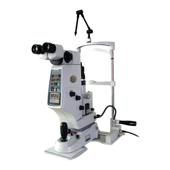
- Page 79 XYC16*RDA001A/E 8.3 Appearance Main body: Operator’s side view Eyepieces Fixation lamp Forehead rest Chinrest elevation control Eye level marker Control panel Base fixing knob Grips Main body: Top view Laser head connector Tonometer mount 8 - 9...
- Page 80 XYC16*RDA001A/E Main body: Patient’s side - Right side view Magnification Slit rotation control change control Chinrest Energy control Hole for mounting the fo- cusing rod Focus shift control Slit width control Aiming rotation control Illumination arm fixing knob Hand switch Microscope arm fixing knob Smart switch Grip...
- Page 81 XYC16*RDA001A/E 8.4 Error Message Table Error No. Symptom Cause Internal structure overheat Internal structure overheat Safety shutter malfunction or detection Safety shutter malfunction sensor failure Aiming shutter malfunction or detection Aiming shutter malfunction sensor failure Insufficient number of laser Failure of the YAG laser system or emissions detection circuit Excessive number of laser...
- Page 82 XYC16*RDA001A/E 8.6 Parameter Setting Tables Abbre Default Contents Setting ress viation Adjustment mode control 0: Normal mode 1: Adjustment mode Control of electric beeps at laser emission 0: Beeps 1: No beeps Unassigned at present Countdown timer Total counter function stop 0: Function 1: Stop Unassigned...
- Page 83 XYC16*RDA001A/E Abbre Default Contents Setting ress viation — Unassigned — Unassigned — Unassigned — Unassigned µ Focus shift value –500 µ Focus shift value –375 µ Focus shift value –250 µ Focus shift value –125 µ Focus shift value 0 µ...
- Page 84 XYC16*RDA001A/E Abbre Default Contents Setting ress viation Detection bit of the energy control Detection bit of the focus shift control Unassigned Unassigned Latency time of single (×10 msec) Value × (10 msec) Latency time of burst (×10 msec) Value × (10 msec) Latency time of others (×10 msec) Value ×...
- Page 85 XYC16*RDA001A/E Abbre Default Contents Setting ress viation 0: Function disabled 1: ENERGY DOWN 2: ENERGY UP 3: AIMING DOWN H01(R) SW functions 4: AIMING UP 5: READY 6: BURST 7: RESET 0: Function disabled 1: ENERGY DOWN 2: ENERGY UP 3: AIMING DOWN H02(L) SW functions...
- Page 86 XYC16*RDA001A/E 8 - 16...
Need help?
Do you have a question about the YC-1800 and is the answer not in the manual?
Questions and answers
My yag works fine but does not fire all the time.Moving the height makes it fire again,any answer?