
Related Manuals for Nidek Medical LM-600


Summary of Contents for Nidek Medical LM-600
- Page 1 AUTO LENSMETER LM-600/600P/600PD LM-600/600P/600PD Mode Mode l OPERATOR’S MANUAL OPERATOR’S MANUAL...
- Page 2 Original instructions NIDEK CO., LTD. : 34-14, Maehama, Hiroishi-cho, Gamagori, Aichi 443-0038, Japan (Manufacturer) Telephone: +81-533-67-6611 Facsimile: +81-533-67-6610 NIDEK CO., LTD : 3F Sumitomo Fudosan Hongo Bldg., 3-22-5, Hongo, (Tokyo Office) Bunkyo-Ku, Tokyo 113-0033, Japan Telephone: +81-3-5844-2641 Facsimile: +81-3-5844-2642 NIDEK INCORPORATED : 47651 Westinghouse Drive, Fremont, California 94539, U.
-
Page 3: Safety Precautions
Use this device properly and safely. BEFORE USE, READ THIS MANUAL. This operator’s manual includes operating procedures, safety precautions, and specifications for the NIDEK AUTO LENSMETER, LM-600/LM-600P/LM-600PD. Cautions for safety and operating procedures must be thoroughly understood before using the device. -
Page 4: Before Use
Usage precautions Before use • Do not use the device for other than the intended purpose. CAUTION NIDEK will not be responsible for accidents or malfunction caused by such misuse. • Never modify nor touch the internal structure of the device. This may result in electric shock or malfunction. -
Page 5: During Use
• Install the device in area where the outlet that the mains plug is inserted into is easily CAUTION accessible during use. In addition, ensure that the power cord can be disconnected without the use of a tool. Otherwise, it may interfere with disconnecting of the power from the input power source in case of abnormality. - Page 6 CAUTION electrical and electronic equipment that may disturb, or be disturbed by, other equipment. The LM-600/LM-600P/LM-600PD complies with these requirements as tabled on pages 113 to 116. Follow the guidance in the tables for use of the device in an electromagnetic environment.
-
Page 7: After Use
After use • While the device is not in use, turn it off. CAUTION • The LM-600P/LM-600PD uses a heat-sensitive printer paper. To keep the printed data for a long period of time, make copies of the printouts. The paper degrades over time and the printed data may become illegible. •... -
Page 9: Table Of Contents
Table of Contents 1. BEFORE USE ........1 1.1 Outline of Device . - Page 10 2.13 After Use ............. 75 2.14 Setting Parameters .
-
Page 11: Before Use
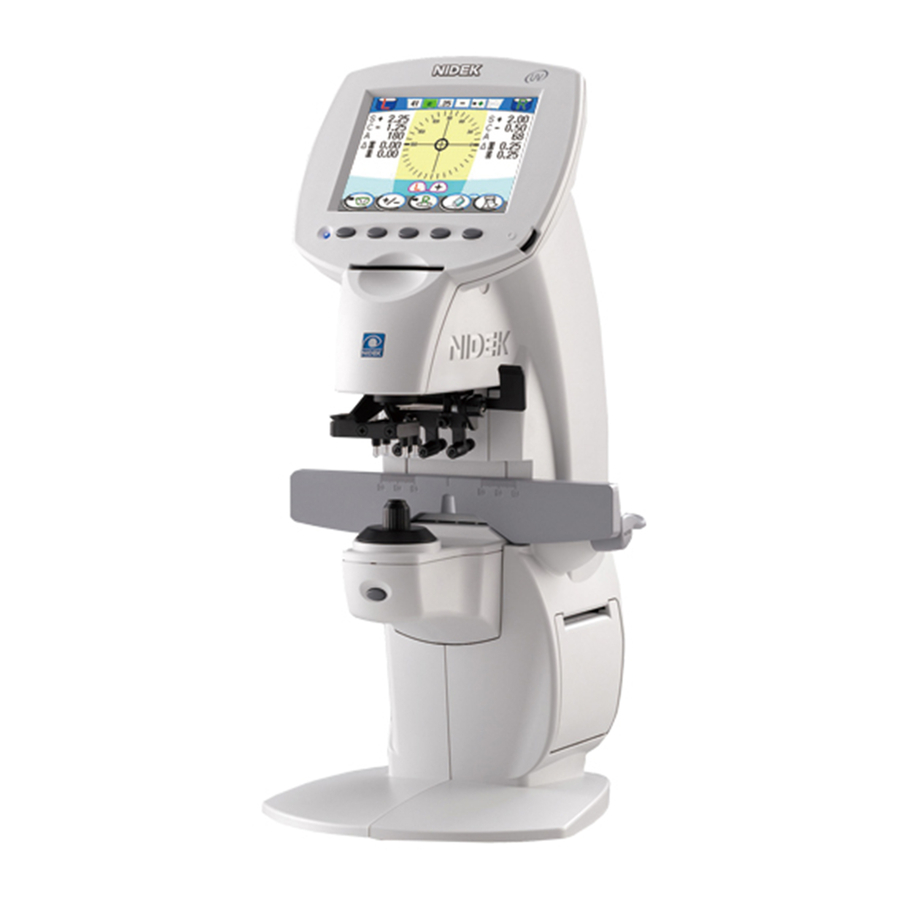
BEFORE USE Outline of Device The NIDEK AUTO LENSMETER LM-600/LM-600P/LM-600PD measures the optical performance of spectacle lenses such as single vision, bifocal (trifocal), and progressive power lenses or contact lenses. This device has a measuring unit and a display unit in front, and a printer unit on the right side (Only the LM-600P/LM-600PD is equipped with the printer). -
Page 12: Configuration
9. Marking lever 3. Function buttons 10. Lens table 4. Eye Care card slot 5. Lens holder lever 11. Lens table lever 6. Nosepiece 7. Read button 12. Printer cover [LM-600] [LM-600PD] 13. Nose slider The LM-600 has no printer. - Page 13 Used to save the measured data. Never remove the Eye Care card while it is being accessed. When the measured data is saved in the LM-600/LM-600P/LM-600PD memory and the Eye Care card is inserted, the data is automatically written. 5. Lens holder lever Used to move the lens holder.
- Page 14 BEFORE USE Configuration 10. Lens table Touched to the bottom of lens frames. The PD can be measured with the scale on the lens table. (LM- 600/LM-600P) Mount the lens frames so that their nosepads come into contact with the nosepiece while aligning the frame center. Bring the lens table close to the lens to read the single-eye PD.
- Page 15 BEFORE USE Configuration [Rear side] 14. Power switch 17. USB port 15. Printer cover lever 16. Power inlet * Remove the cap be- fore connection. 18. Interface connector 14. Power switch Used to turn on or off the power of the device. 15.
-
Page 16: Displays
BEFORE USE Displays Displays 1.4.1 Measurement screen There are four measurement screens, Auto measurement screen, Normal measurement screen, Pro- gressive power lens (PPL) measurement screen, and Contact lens (CL) measurement screen. The screen below shows the normal measurement screen to measure single vision lenses or bifocal (trifocal) lenses. - Page 17 BEFORE USE Displays 2. Setting indications Show each setting of the abbe number, wavelength, indication step, CYL mode, auto read, and state of the Eye Care card. Each setting is changed on the parameter screen. Abbe number Eye Care card Wavelength Auto read Indication step...
- Page 18 BEFORE USE Displays 4. Measurement mode/Lens indication Shows a measurement mode and whether the lens side is specified or not. The R/L indication on the top of the screen also shows the lens side. Normal measurement Measurement of single vision lenses or bifocal (trifocal) lenses PPL measurement When it is detected that a lens is placed in an inverted position, the icon changes to to call attention to it.
- Page 19 BEFORE USE Displays In the setting for measuring contact lenses only, the parameter button is displayed instead. Only when the Contact parameter is set to “Only”, this icon is displayed. When the Icon parameter is set to “Fixed”, the icon of the measurement selection button is displayed without toggle as follows: Changes the screen in the order of Auto measurement o Normal measurement o PPL measurement o CL measurement o Auto measurement...
- Page 20 Printing is not performed. NCP10 When the Eye Care card is inserted, the data is written. NCP20 Data is written to the Eye Care card. Printing and data transmission are not performed. LM-600 Parameters Functions Icons Com mode Printer Prints measured data using the printer of a connected AR, ARK or RKT.
- Page 21 BEFORE USE Displays { PD indications of the measurement screen (LM-600PD only) This is the measurement screen to measure the PD using the lens table and nose slider. The PD can be measured on the screen other than CL measurement screen. The PD of mounted lenses (binocular PD, RPD, LPD) is indicated in 0.5 mm increments.
- Page 22 BEFORE USE Displays { Contact Lens (CL) measurement screen This is the screen to measure contact lenses. SE value The auto read setting is not displayed on the setting indication. In CL measurement, auto read, auto R/L selection, and auto print do not work. A SE value is displayed in addition to lens measured data.
-
Page 23: Prism Layout Screens
BEFORE USE Displays 1.4.2 Prism layout screens Two screens are provided for blocking lenses for heterophoria prescriptions using the prism layout function: Prism entry screen used for entering prism prescriptions and measurement mode screen for measuring lenses. With the prism layout function, the on-screen position of the target is shifted based on the entered prism prescriptions. - Page 24 BEFORE USE Displays 2. Setting indications The indication representing the Auto read setting is not displayed. On the prism layout screens, Auto read is disabled regardless of the setting. The indications of the abbe number, wavelength, indication step, CYL mode, and state of the Eye Care card are displayed in the same manner as those on the measurement screen.
- Page 25 BEFORE USE Displays 7. UP/DOWN button Used to enter prism prescriptions. The indication of the buttons differs according to selection of the rectangular or polar coordinate. Each time the button is pressed, the preset prism data changes in a specified increment. The prism value changes continuously when the button is pressed and held.
- Page 26 BEFORE USE Displays { Measurement mode screen This screen is used for measuring and marking lenses in accordance with preset prism prescriptions entered on the prism entry screen. Enter the measurement mode screen through the prism entry screen. The cylinder +/- button and the print button function in the same manner as on the measurement screen.
-
Page 27: Uv Measurement Screen (Uv Model Only)
BEFORE USE Displays 1.4.3 UV measurement screen (UV model only) This is the screen to display the UV (ultraviolet rays) transmittance. This screen is displayed only when the UV display parameter is set to “Compare”. The UV measured result is displayed visually and emphatically. The UV protective effect can be com- pared after additional measurement. - Page 28 BEFORE USE Displays 5. Compare measurement button Used to compare with the UV transmittance of other lenses. The UV compare screen is displayed when the compare measurement button is pressed after the lens on the nosepiece is changed. The right side 2) is a result of the additional measurement. Additional measurement can be performed repeatedly.
-
Page 29: Parameter Screen
BEFORE USE Displays 1.4.4 Parameter screen This is the screen to set parameters related to each setting of the device. 1. Parameters 2. Parameter settings Page No. 3. Exit button 7. Selection button 4. Back page button 5. Forward page button 6. -
Page 30: Labels
BEFORE USE Labels Labels To call attention to operators, some labels and indications are provided on the device. If labels are curling up or characters fade and become barely legible, contact NIDEK or your autho- rized distributor. Indicates that caution must be taken. Refer to the operator’s manual before use. Indicates the state of the power switch. -
Page 31: Checking Contents
AUTOMATISCHER AUTOMATISCHER SCHEITELBRECHWERTMESSER FRONTOFOCÓMETRO AUTOMÁTICO SCHEITELBRECHWERTMESSER FRONTOFOCÓMETRO AUTOMÁTICO LM-600P LM-600 /LM-600PD Checking Contents Unpack the contents from the shipping carton and check them. The following is included in the standard configuration. • Main body • Nosepiece for contact lenses • Printer paper (3 rolls): LM-600P/LM-600PD only •... -
Page 32: Before First Use
BEFORE USE Before First Use Before First Use Put the device on a stable table and connect the power cord. Put the device on a stable table. Lay the device down gently. Connect the power cord to the power inlet. Power inlet •... - Page 33 BEFORE USE Before First Use Turn the power switch on ( The initial screen is displayed on the display and the device is initialized. Wait for a while until the screen is changed to the measurement screen. Initial screen Initial screen of UV model Make sure that the measurement screen is dis- played.
- Page 34 BEFORE USE Before First Use When the screen is too bright or too dark, adjust the brightness with the contrast knob. Contrast knob Set the supplied printer paper. (LM-600P/LM-600PD only) For details of the setting procedure, see “4.3 Replacing Printer Paper (LM-600P/LM-600PD only)”...
-
Page 35: Operating Procedure
OPERATING PROCEDURE Operation Flow Turning ON the device 2.2 Preparation for Measurement (page 26) Turn the power switch on and set measurement conditions. Measurement 2.3 Setting Lenses (page 29) 2.4 Measuring Single Vision Lenses (page 35) 2.5 Measuring Bifocal Lenses (page 38) 2.6 Measuring Progressive Power Lenses (page 43) 2.7 Measuring Prism Lenses (page 52) 2.8 Measuring Contact Lenses (page 54) -
Page 36: Preparation For Measurement
OPERATING PROCEDURE Preparation for Measurement Preparation for Measurement Make sure that the power switch is turned off ( ) and plug the power cord in the wall outlet. • The electrical outlet must be equipped with a grounding terminal. CAUTION Electric shock may occur in the event of trouble or power leak. - Page 37 OPERATING PROCEDURE Preparation for Measurement { Measurement screen at power-on According to the “Intl. screen” and “Contact” parameters, and the type of the attached nosepiece, the measurement screen displayed after initialization differs. • Settings of the Intl. screen parameter Parameter settings Measurement screen displayed at start-up Auto Normal measurement screen in auto measurement...
- Page 38 OPERATING PROCEDURE Preparation for Measurement • When the parameter is set to “Only”: Regardless of the setting of the Intl. screen param- eter, the CL measurement screen appears. Make sure that the nosepiece is for contact lenses. CL measurement screen { Details of target The target form displayed on the measurement screen can be selected with the Target parameter.
-
Page 39: Setting Lenses
• When a uncut lens is set, the lens table does not need to be used. • Set the lens with the upper side of the lens towards the operator. For the LM-600/LM-600P/LM-600PD, the zero degree direction of the prism base is on the opera- tor’s left as viewed from the front. - Page 40 OPERATING PROCEDURE Setting Lenses • Check that the nose slider is lifted upright Nose slider on the far left. Detection by the nose slider position has a higher priority to select R or L. In such a case, the R/L selection button is disabled.
-
Page 41: Setting Mounted Lenses
OPERATING PROCEDURE Setting Lenses 2.3.2 Setting mounted lenses • When measuring glasses in use or processed lenses, remove dusts and processing waste on the lens before measurement. Otherwise, foreign matters may be attached to the nosepiece or lens holder and damage the lenses. -
Page 42: Setting For Pd Measurement (Lm-600Pd Only)
OPERATING PROCEDURE Setting Lenses 2.3.3 Setting for PD measurement (LM-600PD only) For mounted lenses, the optical center distance between the right and left lenses can be measured. • Precise PD measurement may be difficult with glasses with cylinder-only lenses, high power lenses, or sharply warped frames. - Page 43 OPERATING PROCEDURE Setting Lenses Set the lens table. Pull the lens table lever towards the operator until it touches the bottom of the frames. • Touch the bottom of both frames onto the lens table. If the frames are off the lens table, an error may occur in the axis value. Fix the lens with the lens holder.
- Page 44 OPERATING PROCEDURE Setting Lenses { Message during measurement (LM-600PD) When either of the following operations is performed during R or L detection by the nose slider, a cau- tion message appears. During R or L detection: The R/L selection button is displayed blank •...
-
Page 45: Measuring Single Vision Lenses
OPERATING PROCEDURE Measuring Single Vision Lenses Measuring Single Vision Lenses Single vision lenses are measured on the auto measurement screen or normal measurement screen. Specify the lens side if necessary. Press the L-selection button or R-selec- tion button to specify the left-eye lens or right-eye lens. - Page 46 OPERATING PROCEDURE Measuring Single Vision Lenses • Fixing measured data After the measured data on the screen is fixed and the data is saved in the memory, the R/L indication is inverted. R/L indication when data is fixed Shows that measured data of the lens in the single state is saved in the memory. Shows that measured data of the left-eye lens is saved in the memory.
- Page 47 OPERATING PROCEDURE Measuring Single Vision Lenses { Changing CYL mode Pressing the cylinder +/- button switches the CYL mode between + and -. Pressing the button again returns to the preset mode. Shows that data is displayed in CYL the mode set with the parameter. (White) Shows that data (SPH, CYL, and AXIS) is displayed after reversing the CYL mode (Yellow)
-
Page 48: Measuring Bifocal Lenses
OPERATING PROCEDURE Measuring Bifocal Lenses Measuring Bifocal Lenses Bifocal lenses (or trifocal lenses) are measured sequentially in the order of the distance portion near portion (for trifocal lenses, distance portion intermediate portion near portion). Distance portion Intermediate portion Near portion Trifocal lens Bifocal lens Specify the lens side if necessary. - Page 49 OPERATING PROCEDURE Measuring Bifocal Lenses Display the near ADD power (Add: 1st ADD power). Pull the lens towards the operator to bring the near portion onto the nosepiece. When the ADD power is detected, the auto ADD measurement function places the device into ADD power measurement.
- Page 50 OPERATING PROCEDURE Measuring Bifocal Lenses Bring the near portion onto the nosepiece. The near ADD power (Ad2: 2nd ADD power) appears on the screen. When the measured prism value is not dis- played, “A2” is displayed. • It is not necessary to align the target. Press the read button.
- Page 51 OPERATING PROCEDURE Measuring Bifocal Lenses { Measuring ADD power more accurately These is the procedure for measuring the ADD power without including an error in the measured data made by the distance between the segment and nosepiece. It is especially effective when the base lens is thick. Set the distance portion with the concave side up as shown to the right.
- Page 52 OPERATING PROCEDURE Measuring Bifocal Lenses Press the read button. The measured data of the near ADD power (Add) is fixed. Auto read is disabled so press the read button to fix the measured data.
-
Page 53: Measuring Progressive Power Lenses
OPERATING PROCEDURE Measuring Progressive Power Lenses Measuring Progressive Power Lenses 2.6.1 Measuring uncut lenses Measure a lens at the marks of the distance portion and near portion printed on the lens in the same manner as “2.5 Measuring Bifocal Lenses” (page 38). Distance power measuring position Near power measuring position Horizontal reference line... - Page 54 OPERATING PROCEDURE Measuring Progressive Power Lenses Change the screen to the PPL measurement screen. Press the measurement selection button on the normal measurement screen to display the PPL measurement screen. To switch from the auto measurement screen to the PPL measurement screen, see “{ Screen change in auto measurement”...
- Page 55 OPERATING PROCEDURE Measuring Progressive Power Lenses 2) Move the lens in the horizontal direction to align the target with the vertical line of the crossline. 3) Slowly move the lens inward (upward on the screen) referring to the target to align it with the crossline.
- Page 56 OPERATING PROCEDURE Measuring Progressive Power Lenses Measure the near ADD power. 1) The target indicating the near portion appears. The arrow shows the direction in which the lens should be moved. 2) Move the lens slowly in the direction of the arrow (towards the operator).
- Page 57 OPERATING PROCEDURE Measuring Progressive Power Lenses • Whether to display the indicator for near portion ( ) can be set with the Indicator parameter. When the Indicator parameter is set to “Off”, align the lens referring to the target. When the vertical position is aligned, the arrow disappears.
- Page 58 OPERATING PROCEDURE Measuring Progressive Power Lenses • Auto R/L selection works after ADD power measurement. { Measurement screen in the single state When the lens side is not specified (single state), a round lens is displayed in form on the screen. The measurement procedure is the same as when the lens side is specified.
- Page 59 OPERATING PROCEDURE Measuring Progressive Power Lenses 2) The screen changes to the PPL measure- ment screen automatically. After lens measurement, pressing the print button or clear button returns the screen to the auto measurement screen (normal measurement). { Progressive power lenses for small vertical frame When the height of the processed lens is too small for the near portion to be included, the display changes to alert that the proper near power has not been measured.
- Page 60 OPERATING PROCEDURE Measuring Progressive Power Lenses When the height of the processed lens is small and near portion is lacked, the ADD power cannot be measured with the usual auto read function. The near portion is lacked from a lens shape. When the height of the When the height of the processed lens is sufficient...
- Page 61 OPERATING PROCEDURE Measuring Progressive Power Lenses { PPL measurement screen in PD measurement (LM-600PD only) When PD measurement is performed on the PPL measurement screen, messages such as “Conduct- ing distance measurement...”, “Distance measurement complete”, and “Near measurement complete” and the PD value is alternately displayed. While “Conducting near measurement...”...
-
Page 62: Measuring Prism Lenses
OPERATING PROCEDURE Measuring Prism Lenses Measuring Prism Lenses There is the procedure to measure prism power of mounted prism lenses. Set the Prism parameter in advance. The prism measured value is displayed by polar coordinates. BU/D BI/O The prism measured value is displayed by rectangular coordinates. The prism measured value is not be displayed. - Page 63 OPERATING PROCEDURE Measuring Prism Lenses Bring the eye point marked in Step 1 to the cen- ter of the nosepiece. • It is not necessary to align the target. Press the read button. The measured data is fixed. • When the “Measurement error” message appears, the mark may interrupt the measuring beam.
-
Page 64: Measuring Contact Lenses
OPERATING PROCEDURE Measuring Contact Lenses Measuring Contact Lenses Replace the nosepiece with the one for contact lenses. The top of the nosepiece for contact lenses is smaller than the standard one. Change the screen to the CL measurement screen. Press the measurement selection button on the PPL measurement screen to change the screen to the CL measurement screen. - Page 65 OPERATING PROCEDURE Measuring Contact Lenses Set a contact lens. Put the lens on the nosepiece with the convex side up. For soft contact lenses, set the lens after remov- ing moisture from the surface with a soft cloth. • Hold a contact lens with tweezers or fingers. Be careful not to damage the lens. CAUTION •...
- Page 66 OPERATING PROCEDURE Measuring Contact Lenses Remove the contact lens from the nosepiece. Measure the other lens if necessary. Press the L-selection button or R-selection button to specify the left-eye or right-eye lens. Follow the same steps as the first lens. Press the print button to print out the measured results (, transmit the data, or write the fixed data to Eye Care card.).
-
Page 67: Measuring Uv Transmittance (Uv Model Only)
OPERATING PROCEDURE Measuring UV Transmittance (UV model only) Measuring UV Transmittance (UV model only) A UV (ultraviolet rays) transmittance is measured with the central wavelength of 365 nm (UV-A) by percentage. The UV transmittance can be measured on all measurement screens. To measure the UV transmittance, set the UV, UV step, UV display, Auto correct parameters. - Page 68 OPERATING PROCEDURE Measuring UV Transmittance (UV model only) When the UV display parameter is set to “Compare”: The screen changes to the UV measurement screen and the measured result is displayed. Target indication The range of inside of the circle is within 2 Buttons on UV measurement screen Used to correct the UV transmittance to 100%.
- Page 69 OPERATING PROCEDURE Measuring UV Transmittance (UV model only) 2) The measured results of the two lenses are displayed on the UV compare screen simulta- neously. The left side 1) is original measured result and right side 2) is that of additional one. •...
-
Page 70: Marking
OPERATING PROCEDURE Marking 2.10 Marking 2.10.1 Marking at the optical center Marking is performed to indicate the optical center position and axis direction. • To measure the PD of mounted lenses, mark a lens at the optical center of both the right- eye and left-eye lenses. - Page 71 OPERATING PROCEDURE Marking • When marking a cylinder lens in the bus direction, adjust the axis to 180°. Mark the lens. Press down the marking lever to mark the lens. Three points in a line parallel to the lens table are marked.
-
Page 72: Marking For Prism Prescription (Prism Layout)
OPERATING PROCEDURE Marking 2.10.2 Marking for prism prescription (Prism Layout) This is the procedure to mark lenses for heterophoria prescription. The prism alignment function allows the operator to easily determine the marking point on the lens. Prism layout function Prior entry of the prism prescription causes the on-screen target to move opposite to the direction by the amount of the prism data. - Page 73 OPERATING PROCEDURE Marking Set the prism representation method with the coordinate system button in accor- dance with the prism representation method of the prism data on the prescription. Each the coordinate system button is pressed, the coordinate system toggles between the rectangular coordinate and polar coordinate systems.
- Page 74 With the LM-600/LM-600P/LM-600PD, the zero-degree direction of the prism base is on the operator’s left as viewed from the front. Be aware that the orientation of the lens set on the LM-600/LM-600P/LM-600PD is opposite in orientation of the lens set on a manual lensmeter or blocker.
- Page 75 OPERATING PROCEDURE Marking Hold the next screen button to return to the measurement screen. Extended pressing of the button changes the icon display to the exit button . Releas- ing the button returns to the measurement screen. { When measuring and marking lenses in a row Enter prism prescriptions according to Steps 1 to 7 of “{ Only when marking lenses”...
- Page 76 OPERATING PROCEDURE Marking As necessary, measure and mark the other lens. Change the selected lens with the L selection button or R selection button Measure and mark the lens in the same manner. Press the print button to print out the mea- sured result (, transmit the data, or write the fixed data to Eye Care card.).
-
Page 77: Marking For Prism Prescription (Measurement Screen)
If the lens is set with the wrong side towards the operator, the marked lens does not fol- low prescription. For the LM-600/LM-600P/LM-600PD, the zero degree direction is on the operator’s left. Be aware that the lens should be set with the upper side of the lens towards the operator, which is opposite in orientation of the lens with a manual lensme- ter or a blocker. - Page 78 If the lens is set with the wrong side towards the operator, the marked lens does not fol- low prescription. For the LM-600/LM-600P/LM-600PD, the zero degree direction is on the operator’s left. Be aware that the lens should be set with the upper side of the lens towards the operator, which is opposite in orientation of the lens with a manual lensme- ter or a blocker.
-
Page 79: Printing (Lm-600P/Lm-600Pd Only)
OPERATING PROCEDURE Printing (LM-600P/LM-600PD only) 2.11 Printing (LM-600P/LM-600PD only) Press the print button to print out the measured data. • Print the data out after making sure that the measured data is fixed. When the print button is pressed before the measured data is fixed, the measured data is fixed and printed out. -
Page 80: Connecting To The Ar, Ark Or Rkt And Setting Parameters
• Be sure to turn off each device before connecting the interface cable, etc. CAUTION Connecting the cable with power on may cause malfunction. Connect the AR, ARK or RKT to the interface connector of the LM-600/LM-600P/LM- 600PD with the interface cable (option: OPIF-6). Interface connector... - Page 81 OPERATING PROCEDURE Printing (LM-600P/LM-600PD only) { Setting procedure Set the following parameters on the LM-600/LM-600P/LM-600PD and AR, ARK or RKT. Set the following parameters related to communications on the LM-600/LM-600P/LM- 600PD: Parameter Settings Printer AR print Com Mode NIDEK Baud Rate...
-
Page 82: Data Save To The Eye Care Card
Even if data is attempted to be written, the data is not written. 2.12.1 Writing of fixed data to the Eye Care card { When the Eye Care card is inserted before measurement Insert the Eye Care card when the LM-600/LM- Eye Care card slot 600P/LM-600PD has no measured data in the internal memory. - Page 83 OPERATING PROCEDURE Data save to the Eye Care card • Never remove an Eye Care card while it is being accessed. While the card is being accessed, the icon is displayed in green. When trying to remove the card while it is being accessed, data is not written successfully and the Eye Care card may be irreparably damaged.
-
Page 84: Erasing Data On The Eye Care Card
OPERATING PROCEDURE Data save to the Eye Care card Indications of the Eye Care card icon The Eye Care card is not inserted. (White): The Eye Care card is inserted. (Yellow): The Eye Care card is being accessed. (Green): Never touch the card. An error occurs while the Eye Care card is being accessed. -
Page 85: After Use
OPERATING PROCEDURE After Use 2.13 After Use Turn the device off. When the measurement screen is displayed, turn the power switch off ( • Turning off the power when the parameter screen is displayed may not save the set parameter settings. Parameter settings are saved when the exit button , back page button , or forward... -
Page 86: Setting Parameters
OPERATING PROCEDURE Setting Parameters 2.14 Setting Parameters The LM-600/LM-600P/LM-600PD contains the function to change each parameter setting of the device according to your needs and preference. There are parameters related to the indication, measurement, printing, and communication. The procedure for changing and checking each parameter setting is described as follows. - Page 87 OPERATING PROCEDURE Setting Parameters Change the parameter setting with the selection button The contents within the frame are those currently selected for setting. For details of the parameter settings, see “2.14.1 Parameter tables” (page 78). In the parameters necessary for entering numerical values, the selection buttons are dis- played as follows.
-
Page 88: Parameter Tables
OPERATING PROCEDURE Setting Parameters 2.14.1 Parameter tables <Page 1> * Underlined options indicate factory settings. Parameter Settings Category Step 0.25, 0.12, 0.06, 0.01 (D) Measurement Cylinder +, +/-, - indication Prism Off, P-B, BU/D BI/O Abbe select A:, B:, C:, Com Standard of measurement Wavelength... - Page 89 OPERATING PROCEDURE Setting Parameters 6 : Prism layout This parameter is for switching the screen to the prism layout screen. <Page 2> * Underlined options indicate factory settings. Parameter Settings Category Auto R/L Off, On Off, Auto RD S Auto function Auto RD R/L Off, Dist.
- Page 90 OPERATING PROCEDURE Setting Parameters When the lens is aligned until the target changes to (cross) (or ), the measured data is automatically fixed without pressing the read button. After auto read, when alignment is performed again until the target changes to ), auto read is performed again.
- Page 91 AR print pressing the print button. Data transmission is also performed. • “On” is disabled with the LM-600. • When the Printer parameter is set to “AR print”, the parameters “Print density”, “Paper cut”, “Auto cutter”, and “Eco print” are disabled.
- Page 92 OPERATING PROCEDURE Setting Parameters 21 : Auto prt. S This is for selecting whether to print out the measured data by removing the lens after the data is fixed in the single state (R/L not specified). On the CL measurement screen, this function is disabled. 22 : Auto prt.
- Page 93 OPERATING PROCEDURE Setting Parameters <Page 4> * Underlined options indicate factory settings. Parameter Settings Category Intl. screen Auto, Normal, Progressive, Contact On-screen Target indication Guide Off, On Beep Off, Low, Mid, Hi Other function Auto off Off, 1, 3, 5, 10, 15, 30, 60 (min) Color Blue, Red, Green On-screen...
- Page 94 OPERATING PROCEDURE Setting Parameters <Page 5> * Underlined options indicate factory settings. Parameter Settings Category Com mode Off, NIDEK, PC, NCP10, NCP20 Baud rate 1200, 2400, 4800, 9600, 19200 (bps) Parity Off, Odd, Even Communication Data bits 7bit, 8bit function Stop bits 1bit, 2bit CR code...
- Page 95 OPERATING PROCEDURE Setting Parameters • In order to connect the LM-600/LM-600P/LM-600PD with external computers, ask your authorized distributor for the interface manual which explains the details of the communication protocols. PD parameter (LM-600PD only) The PD parameter is displayed on page 5 of the LM-600PD parameter screen.
- Page 96 Parameters No. 39 to 45 are the items when the Com mode parameter is set to “NCP20”. 39 : Source This is for setting the port number of the source (LM-600/LM-600P/LM-600PD) from 0 to 255. 40 : Destination This is for setting the port number of the destination (receiving device) from 0 to 255.
- Page 97 OPERATING PROCEDURE Setting Parameters <Page 7> (UV model only) Parameter Settings Category Off, On, With UV step 1, 5 (%) UV measurement function UV display Compare, Simple Auto correct Off, On, Silent 46 : UV This is for selecting whether to perform UV measurement UV measurement is not performed by extended pressing of the read button.
-
Page 98: Entering Comments
OPERATING PROCEDURE Setting Parameters 2.14.2 Entering comments The comments in communication print can be changed. (Factory setting: NIDEK LM-600/NIDEK LM- 600P/NIDEK LM-600PD). Display the parameter screen. Press and hold the measurement selection but- ton until the icon changes to and release the button. - Page 99 OPERATING PROCEDURE Setting Parameters Press the right switch or left switch to select the entry position. The cursor indicates the position where a char- acter is entered or changed. Up to 24 characters can be entered in two lines. Move the cursor in the entry position. Change the contents with the selection button and/or Move the cursor to the desired character in the...
- Page 100 OPERATING PROCEDURE Setting Parameters...
-
Page 101: Connecting To The Nidek Motorized Refractor (Rt) Or Computer
OPERATION WHEN PERIPHERAL DEVICES ARE CONNECTED The LM-600/LM-600P/LM-600PD transmits data to an external device such as the NIDEK motorized refractor, computer, and Eye Care card system. The optional foot switch can be used instead of the read button to read measured data. -
Page 102: Connecting Procedure
Interface cable (optional) To RT or computer { Connecting a computer with USB Connect the optional USB cable between the USB port of the LM-600/LM-600P/LM-600PD and the USB port of a computer. The USB driver included in the optional USB cable needs to be installed in the computer. -
Page 103: Operating Procedure
When the LM-600/LM-600P/LM-600PD is connected to a computer, it does not receive a Data No. (ID No.). The measured data is printed. When the LM-600/LM-600P/LM-600PD is connected to the RT, the data No. (ID No.) is also printed. • Disconnect the interface cable while pressing Button the button on the connector. -
Page 104: Connecting The Foot Switch
OPERATION WHEN PERIPHERAL DEVICES ARE CONNECTED Connecting the Foot Switch Connecting the Foot Switch The optional foot switch can be used instead of the read button to read measured data. In such cases when a number of lenses are mea- sured in the Lab system, the foot switch allows for measurement while holding lenses both hands. -
Page 105: Maintenance
MAINTENANCE Troubleshooting In the event that the device does not work correctly, correct the problem according to the following table before contacting your authorized distributor. Symptom Action • The power cord may not be correctly connected. The LCD does not turn on. Reconnect it securely. -
Page 106: Error Messages And Countermeasures
MAINTENANCE Error Messages and Countermeasures Error Messages and Countermeasures If a message appears on the lower part of the screen, take measures according to the table below. Should a service visit be necessary, please prepare the details of the message and symptom along with the serial number of the device. - Page 107 MAINTENANCE Error Messages and Countermeasures Error message Cause and countermeasure • Correct communication is not performed with other devices. Check the interface cable. Communication error Check that the connected device is turned on. Check that the parameters related to communication are correctly set. •...
-
Page 108: Replacing Printer Paper (Lm-600P/Lm-600Pd Only)
MAINTENANCE Replacing Printer Paper (LM-600P/LM-600PD only) Replacing Printer Paper (LM-600P/LM-600PD only) When a red line appears on the side of the printer paper, it means that the paper is running short. In such a case, stop using the printer and replace the roll with a new one. •... - Page 109 MAINTENANCE Replacing Printer Paper (LM-600P/LM-600PD only) Set a new printer paper.. Set the paper as shown in the figure to the right. Leave the end of the paper out from the cover. • When the roll is set upside down, the data is not printed correctly. •...
-
Page 110: Ink Refilling
MAINTENANCE Ink Refilling Ink Refilling 4.4.1 Ink cartridge When markings become faint, replace the ink cartridge. Use the specified cartridge for refills. Replace the optional red or blue ink cartridge in the same manner. Press the tip of the ink cartridge and remove the C-ring with tweezers. -
Page 111: Ink Pad Type (Optional)
MAINTENANCE Ink Refilling 4.4.2 Ink pad type (optional) When markings become faint, add some ink. Remove the ink pad. Push the pad to the right and pull it out of the holder. Add ink. Add some ink to the pad. •... -
Page 112: Cleaning The Protective Glass
MAINTENANCE Cleaning the Protective Glass Cleaning the Protective Glass When the “Dust detected. Please clean lens.” message appears at power-on, clean the protective glass. If dust settles on the protective glass, it may affect the measurement accuracy. • Clean the protective glass under the nosepiece with a blower brush. CAUTION The dust may include sharp particles. -
Page 113: Adjusting The Lens Table
MAINTENANCE Adjusting the Lens Table Adjusting the Lens Table Adjust the feel of the lens table lever movement to be heavy or light. Remove the lens table lever. Adjustable screw Pull it out straight. Setscrew Loosen the setscrew on the adjustable screw with a flatblade screwdriver. -
Page 114: Cleaning
MAINTENANCE Cleaning Cleaning 4.7.1 Cleaning the device exterior When the cover or panel of the device becomes dirty, wipe with a soft cloth. For severe stains, immerse the cloth in a neutral detergent, wring well, and wipe. Finally wipe with a dry and soft cloth. •... -
Page 115: Cleaning The Eye Care Card Slot
MAINTENANCE Cleaning 4.7.3 Cleaning the Eye Care card slot Following an extended period of use, grime may become adhered to the contacts of the Eye Care card slot. If left as is, the data may not be read or written properly. In such a case, clean the contacts with a contact cleaner Eye Care for contact-type IC card reader/writer. -
Page 116: List Of Replacement Parts
MAINTENANCE List of Replacement Parts List of Replacement Parts Part name Part number Note Printer paper 31001-E031 Width 58 mm, Length 25 m Ink cartridge (White) 31001-3373 White ink (3 packs), with C-ring Ink cartridge (Red) 31001-3371 Red ink (3 packs), with C-ring Ink cartridge (Blue) 31001-3372 Blue ink (3 packs), with C-ring... -
Page 117: Specifications And Accessories
SPECIFICATIONS AND ACCESSORIES Classifications [Classification of LED product] Class 1 The LM-600/LM-600P/LM-600PD (UV model only) is classified as a Class 1 LED Prod- uct. The Class 1 LED Product that is safe during use, including long-term direct intrabeam view- ing, even when exposure occurs while using optical viewing instruments (eye loupes or bin- oculars). -
Page 118: Specifications
SPECIFICATIONS AND ACCESSORIES Specifications Specifications { Measuring items • Spherical power (lens for glasses) -25.00 to +25.00 D 0.01/ 0.06/ 0.12/ 0.25 D increments [Accuracy] Measurable range (D) Accuracy (D) 0.06 ± ± 0.09 0.12 ± 0.18 ± ± 0.25 The accuracy specifications are based on the results of test lens measured in accordance with ISO 8598 (lensmeter). -
Page 119: Measurement Mode
The fixed data is automatically released by setting a new lens on the nosepiece. { Applicable lenses • Lens diameter Lenses for glasses:20 to 120 mm in diameter (LM-600/LM-600P) 20 to 100 mm in diameter (LM-600PD) Contact lenses: Larger than the inner diameter of the nosepiece (5 mm in diameter) •... - Page 120 SPECIFICATIONS AND ACCESSORIES Specifications • Power source AC 100 (±10%) to 240 (±10%) V, 50/60 Hz * Fuses (240 V, 4 A, two units) are included in the internal electrical power source.* • Power consumption 40 VA { Environmental conditions (during use) •...
-
Page 121: Standard Configuration
SPECIFICATIONS AND ACCESSORIES Standard Configuration Standard Configuration 5.3.1 Standard accessories • Power cord 1 unit • Dust cover 1 unit • Nosepiece for contact lenses 1 unit • Printer paper (LM-600P/LM-600PD only) 3 rolls • Operator’s manual 1 volume • Measuring Progressive Power lenses explanation sheet 1 sheet 5.3.2 Optional accessories... - Page 122 SPECIFICATIONS AND ACCESSORIES Standard Configuration...
-
Page 123: Emc (Electromagnetic Compatibility)
Guidance and manufacturer's declaration - electromagnetic emissions The LM-600/LM-600P/LM-600PD is intended for use in the electromagnetic environment specified below. The customer or the user of the LM-600/LM-600P/LM-600PD should assure that it is used in such an environment. Emissions test Compliance... - Page 124 Guidance and manufacturer's declaration - electromagnetic immunity The LM-600/LM-600P/LM-600PD is intended for use in the electromagnetic environment specified below. The customer or the user of the LM-600/LM-600P/LM-600PD should assure that it is used in such an environment. Immunity test IEC 60601 test level...
- Page 125 Guidance and manufacturer's declaration - electromagnetic immunity The LM-600/LM-600P/LM-600PD is intended for use in the electromagnetic environment specified below. The customer or the user of the LM-600/LM-600P/LM-600PD should assure that it is used in such an environment. Immunity test IEC 60601 test level...
- Page 126 Recommended separation distances between portable and mobile RF communications equipment and the LM-600/LM-600P/LM-600PD The LM-600/LM-600P/LM-600PD is intended for use in an electromagnetic environment in which radiated RF disturbances are controlled. The customer or the user of the LM-600/LM-600P/LM-600PD can help prevent...
-
Page 127: Index
INDEX Measurement mode screen •••••••••••••••••••••••••••••••••• 16 Measurement selection button ••••••••••••••••••••••••••••••••8 Alignment circle •••••••••••••••••••••••••••••••••••••••••••••••••• 8 Auto read •••••••••••••••••••••••••••••••••••••••••••••••••••••••••• 7 AXIS bar ••••••••••••••••••••••••••••••••••••••••••••••••••••••••••• 8 Next screen button ••••••••••••••••••••••••••••••••••••••••••••• 14 Nose slider •••••••••••••••••••••••••••••••••••••••••••••••••••••• 32 Nosepiece •••••••••••••••••••••••••••••••••••••••••••••••••••••••••3 Back page button •••••••••••••••••••••••••••••••••••••••••••••• 19 Parameter settings ••••••••••••••••••••••••••••••••••••••••••••• 19 Clear button •••••••••••••••••••••••••••••••••••••••••••••••••••••••... - Page 128 INDEX...
Need help?
Do you have a question about the LM-600 and is the answer not in the manual?
Questions and answers
how do you change marker pins on the lm600p