Table of Contents
Advertisement
Quick Links
Advertisement
Table of Contents

Related Manuals for Vertiv Liebert NXC 0060kTJ1AFN02000


Summary of Contents for Vertiv Liebert NXC 0060kTJ1AFN02000
- Page 1 Liebert® NXC 0kVA User Manual...
- Page 2 NXC 60kVA UNINTERRUPTIBLE POWER SUPPLY USER MANUAL 10H52246UM60 - rev. 1...
- Page 3 SAFETY PRECAUTION All rights, including rights of translation, reproduction in any form or other usage of this document, or any part of it, are reserved. Transgressors will be liable for damages. All rights, including rights created by patent grant or registration of utility model or design, are reserved.
-
Page 4: Product Safety
Near sources of heat or strong electromagnetic interference Disclaimer Vertiv disclaims any and all responsibility or liability for defects or malfunctions caused by: Application range or operating environment outside the specified limits Unauthorized modification, improper installation or operation ... -
Page 5: Safety Precaution
This manual contains information explaining how to install and operate single UPS modules and parallel systems consisting of Vertiv NXC 60kVA UPS. Read this manual thoroughly before installing, using and servicing the UPS. Important This UPS has been designed for commercial and industrial applications in the second environment (see product standard IEC/EN 62040-2:2006). - Page 6 SAFETY PRECAUTION Warning The UPS upstream distribution protection equipment shall be selected in accordance with the details in 3.1.4 Selecting the UPS I/O Switch and shall comply with the local electrical regulations. General safety precautions (For users) Like other types of large power equipment, the UPS and battery circuit breaker box/battery cabinet contain high voltages. Because components with high voltage can be accessed only by opening the front door (which must be kept locked), the risk of contact with high voltage has been minimized.
- Page 7 This Manual Describes The Following Equipment Product Model Liebert NXC 60kVA NXC 0060kTJ1AFN02000 User Manual 10H52246UM60 - Rev. 1 - 01/2017...
-
Page 8: Table Of Contents
CONTENTS Contents Chapter 1 Overview ....................................10 1.1 Features ....................................10 1.2 Design Concept ..................................10 1.2.1 System Design ............................... 10 1.2.2 Bypass ................................11 1.2.3 System Control Principle ..........................11 1.2.4 UPS Power Supply Switch Configuration ......................12 ... - Page 9 CONTENTS 4.2.2 Main Screen ..............................38 4.2.3 Default Screen ..............................38 4.3 Detailed Description Of Menu Items ............................39 4.4 Prompt Window ..................................41 4.5 Alarm List ....................................41 Chapter 5 UPS Operation Introduction ..............................44 ...
- Page 10 CONTENTS Chapter 8 Options ....................................67 8.1 Brief Description of Options ..............................67 8.1.1 Bypass Load Sharing Inductor Kit ........................67 8.1.2 Internal Battery Kit ............................70 8.1.3 Battery Temperature Compensation Kit ......................74 8.1.4 IS-UNITY-DP Card ............................
-
Page 11: Chapter 1 Overview
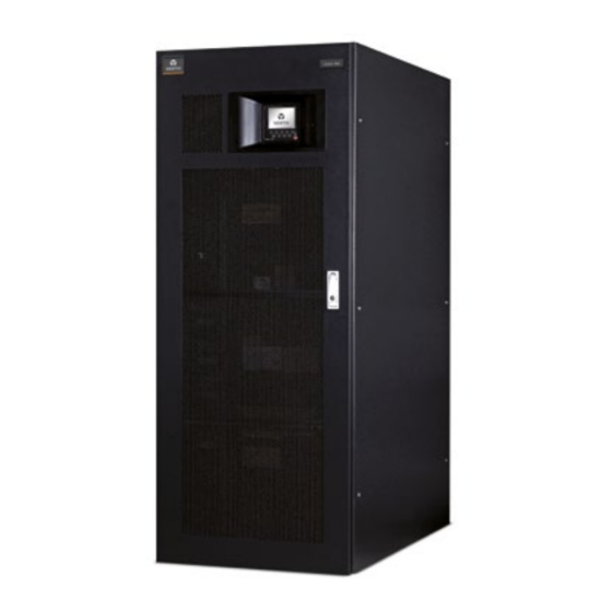
OVERVIEW Chapter 1 Overview This chapter provides a brief introduction to the features, appearance and components, design concept, parallel system, operating mode, battery management and battery protection of the Liebert NXC 60kVA UPS (UPS for short). 1.1 Features The UPS is connected between a mains power source and a critical load (e.g. a computer) in order to provide a high quality power supply for the latter. -
Page 12: Bypass
In the event of an inverter failure, an automatic inverter switching failure, a blown output fuse or a bypass STS failure, the load is transferred automatically to the bypass supply line, without interrupting the power supply to the loads. If any of these fault conditions occur, please contact your local Vertiv customer service center for technical support. -
Page 13: Ups Power Supply Switch Configuration
OVERVIEW power to the loads. The maintenance bypass can be manually selected using the maintenance bypass switch, and disconnected by turning the switch to OFF. Warning If the UPS system consists of two or more UPS modules, and the load capacity exceeds the single module capacity, do not use the internal maintenance bypass switch. -
Page 14: Operating Modes
EOD voltage, when the mains is restored, the UPS will restart automatically after a certain delay. This function, and the automatic restart type, can be set-up by Vertiv authorized service engineers. During the automatic restart delay period, the UPS will charge the battery to protect the load against the risk of power interruptions in the event of a new mains failure. - Page 15 OVERVIEW Static switch UPS output Bypass input Output switch Bypass input switch Figure 1-5 Schematic diagram of bypass mode Maintenance mode As illustrated in Figure 1-6, if it is necessary to service the UPS or carry out maintenance work on it, the manual maintenance bypass switch may be used to transfer the load to maintenance bypass, with no interruption in power to the load.
-
Page 16: Battery Management
(set to "OFF") in order to disable static bypass operation, and the battery becomes optional, depending on whether battery mode is required, or not. 1.5 Battery Management The following battery management functions are set-up by the service engineer by modifying the Vertiv software settings. 1.5.1 Normal Function 1. -
Page 17: Battery Temperature Compensation
BCB alarm The BCB alarm occurs when the external BCB opens, if the UPS is fitted with the Vertiv BCB option. The external battery is connected to the UPS via the BCB. The BCB is manually closed and tripped by the UPS control circuit. -
Page 18: Chapter 2 Mechanical Installation
MECHANICAL INSTALLATION Chapter 2 Mechanical Installation This chapter provides a brief introduction to the UPS mechanical installation procedure, including the precautions, pre-installation inspection, environmental and mechanical requirements and the installation diagram. 2.1 Precautions The following paragraphs describe the environmental and mechanical requirements, and the mechanical considerations that must be taken into account when planning the positioning and cabling of the UPS equipment. -
Page 19: Unpacking
MECHANICAL INSTALLATION Table 2-1 Tools Name Drawing Name Drawing Electric hand drill Adjustable wrench Flat blade screwdriver Cross head screwdriver Stepladder Forklift Drill Wire cutting pliers Claw hammer Diagonal cutting pliers Insulating shoes Antistatic gloves Electrician's knife Cable tie Insulating tape Insulating gloves Crimping pliers Heat shrinkable tube... - Page 20 MECHANICAL INSTALLATION Figure 2-3 Removing side panels and top cover 2. Remove and store the bolts that secure the UPS to the pallet (see Figure 2-4). Then, use the forklift (inserting the forks in the direction indicated in Figure 2-4) to move the cabinet to the place where it is to be installed. Inserting direction Fixing bolt Bottom pallet...
-
Page 21: Initial Inspection
MECHANICAL INSTALLATION Foot Foot fixing piece Figure 2-5 Diagram illustrating how to raise the feet 2.5 Initial Inspection Before installing the UPS, carry out the following inspections: 1. Ensure that the UPS installation environment meets the environmental requirements indicated in the product technical specifications, especially the ambient temperature, ventilation conditions and the dust levels. -
Page 22: Mechanical Requirements
MECHANICAL INSTALLATION charging process, connect the UPS to the mains temporarily and activate the battery by recharging it. 2.7 Mechanical Requirements 2.7.1 Moving the UPS Warning 1. Ensure any any equipment used ot lift or move the UPS has sufficient lifting capacity. 2. - Page 23 MECHANICAL INSTALLATION 1433 Top view (door open) inlet inlet outlet outlet 1528 Left side view Right side view Front view Ф36 signal cable inlet Cable access area Ф11 foot installation hole Bottom view Figure 2-7 Top/front/side/bottom view of the UPS (unit: mm) User Manual 10H52246UM60 - Rev.
-
Page 24: Chapter 3 Electrical Installation
Earth cable Battery 60kVA (3-in 3-out) If the user’s cable CSA exceeds the value recommended in Table 3-2, please contact Vertiv service engineers. 3.1.4 Selecting the UPS I/O Switch Note The specified upstream breakers below are required to obtain the conditional short-circuit current rating, Icc at 10kA symmetrical rms. -
Page 25: Distance Between The Ups Connection Point And The Floor
ECLECTRICAL INSTALLATION port capacity of input Capacity capacity of output external switch external switch 60kVA Terminal 125A (3P), bypass 10kA DC 200A (4P) Terminal blcok 125A (3P) (3-in 3-out) block 125A (3P) 3.1.5 Distance Between The UPS Connection Point And The Floor See Table 3-4 for details. -
Page 26: Power Cable Connection Procedure
ECLECTRICAL INSTALLATION The RCCB symbols are shown in Figure 3-1. Figure 3-1 RCCB symbols The UPS has an internal EMC filter, therefore the protective earth cable leakage current is 0 ~ 1000mA. We recommend verifying the RCD sensitivity of the upstream input distribution and the downstream distribution (to the load). - Page 27 ECLECTRICAL INSTALLATION Step 3 Step 1 Cover panel of switch area Step 4 Step 2 Note: Step 1: Remove the left top cover, lead battery input cable and PE input cable into the cabinet, and route them along left side panel to cabinet base. Step 2: Remove the cover panel of switch area, respectively connect cables to battery input terminals and PE input terminal.
- Page 28 ECLECTRICAL INSTALLATION Step Bottom plate Note: Step: Remove the bottom plate, lead cables into the cbainet and connect them to corresponding terminals. Figure 3-4 Power cables wiring route (bottom cable access) Warning Before connecting the cables, make sure that all external power switches are off, and position the necessary warning signs in order to prevent inadvertent operation of the switches.
- Page 29 ECLECTRICAL INSTALLATION Connecting the system input 1. 3-in 3-out, common input configuration (factory default) Refer to Figure 3-5, connect the AC input cables to the bypass input terminals (bA-bB-bC) in the cabinet, and ensure that the three copper shorting bars are connected between the rectifier input terminals (mA-mB-mC) and the corresponding bypass input terminals.
-
Page 30: Signal Cable Wiring
ECLECTRICAL INSTALLATION 2. 3-in 3-out, split bypass configuration Refer to Figure 3-6, remove the three shorting copper bars between the rectifier input terminals (mA-mB-mC) and the bypass input terminals (bA-bB-bC). Connect the rectifier input cables to the rectifier input terminals (mA-mB-mC) in the cabinet, and connect the bypass input cables to the bypass input terminals (bA-bB-bC) in the cabinet. -
Page 31: Input Dry Contact Port
ECLECTRICAL INSTALLATION controlled by the communication box in the UPS. As shown illustrated in Table 3-7, the communication box provides the following ports: RS232 LBS 1 PARA 1 INTELLISLOT 1 INTELLISLOT 2 INTELLISLOT 3 RS485-1 RS485-2 LBS 2 PARA 2 Note: LBS communication port Parallel communication port... -
Page 32: Bcb Port
ECLECTRICAL INSTALLATION Table 3-5 Description of input dry contact ports J1 and J5 Silkscreen Port Pin No. Pin name Meanings Generator is connected. Shorted between 1.1 and 1.2: Generator generator mode; open between 1.1 and 1.2: normal mode mode input External maintenance bypass switch state. -
Page 33: Remote Epo Input Port
ECLECTRICAL INSTALLATION Table 3-7 Description of backfeed protection dry contact port J3 Silkscreen Port Pin No. Pin name Meanings Rectifier/bypass backfeed normally open BFP_O contact. Open when there is no backfeed Rectifier/Bypass BFP_S Rectifier/bypass backfeed common contact backfeed output Rectifier/bypass backfeed normally closed BFP_C contact. -
Page 34: Intellislot Port
ECLECTRICAL INSTALLATION Table 3-9 Pins definition of RS485 communication port 1, 2 3, 6 4, 5 Definition Connect to monitoring host Figure 3-12 Cable connection diagram of RS485 communication port 3.2.10 Intellislot Port The Intellislot ports are used for installing optional cards on site, including IS-UNITY-DP card, IS-Relay card, IS-485L card, IS-WEBL card. - Page 35 ECLECTRICAL INSTALLATION Step 1 Top cover Step 2 Note: Step 1: Remove the top cover, lead cables into the cabinet. Step 2: Connect cables to corresponding terminals. Figure 3-13 Signal cables wiring route (top cable access) User Manual 10H52246UM60 - Rev. 1 - 01/2017...
- Page 36 ECLECTRICAL INSTALLATION Step Cable inlet (one for left and one for right) Note: Step: Take priority selection of the right side cable inlet, lead cables into the cabinet and route them along the cabinet inside, then connect them to corresponding terminals. Figure 3-14 Signal cables wiring route (bottom cable access) User Manual 10H52246UM60 - Rev.
-
Page 37: Chapter 4 Operator Control And Display Panel
OPERATOR CONTROL AND DISPLAY PANEL Chapter 4 Operator Control And Display Panel This chapter describes the functions and use of the elements on the UPS operator control and display panel, provides LCD display information, including the LCD screen types, detailed menu messages, prompt windows and the UPS alarm list. -
Page 38: Audible Alarm (Buzzer)
OPERATOR CONTROL AND DISPLAY PANEL 4.1.2 Audible Alarm (Buzzer) UPS activity is accompanied by the two different sounds, as listed in Table 4-3. Table 4-3 Description of audible alarm Alarm sound Meaning Alarm generated in the event of a general fault, for example, overload, battery disconnected, fan failure, parallel load sharing failure and battery discharge Beep every other second pre-alarm, etc. -
Page 39: Lcd Screen Type
OPERATOR CONTROL AND DISPLAY PANEL 4.2 LCD Screen Type 4.2.1 Start Screen Upon UPS start, the UPS executes a self-test, and the start screen appears and remains approximately 25 seconds, as shown in Figure 4-2. Figure 4-2 Start screen 4.2.2 Main Screen After the self-test has been completed, the main screen appears, as shown in Figure 4-3. -
Page 40: Detailed Description Of Menu Items
OPERATOR CONTROL AND DISPLAY PANEL Figure 4-4 Default screen 4.3 Detailed Description Of Menu Items The description that follows refers to the LCD main screen, as shown in Figure 4-4. System information window The system information window displays the current time, UPS name, configuration and alarm silencing state. This window requires no actions on the part of the user. - Page 41 OPERATOR CONTROL AND DISPLAY PANEL Table 4-7 escription of menu window and data window items Menu Item Explanation L-N voltage (V) Phase voltage L-N current (A) Phase current Mains Frequency (Hz) Input frequency L-L voltage (V) Line voltage Power factor Power factor L-N voltage (V) Phase voltage...
-
Page 42: Prompt Window
OPERATOR CONTROL AND DISPLAY PANEL Menu Item Explanation Perform a full discharge of the battery to obtain an accurate battery capacity Battery capacity test measurement. Load must be between 20% and 80% UPS self-test. When the user activates this function, a window appears about System test 5s later to show the test result Manually stop a battery maintenance test, battery capacity test or system... - Page 43 OPERATOR CONTROL AND DISPLAY PANEL Alarm Explanation At least one mains input phase voltage is within 132V ~ 176V, therefore the load should be Mains undervoltage derated Mains freq. abnormal The mains frequency is outside specifications and results in rectifier shutdown Mains phase reversed The AC input phase rotation is reversed Input feedback...
- Page 44 2. If the alarm is generated as the result of a software value set-up by an Vertiv authorized engineer, and you wish to change the setting, please contact your local Vertiv customer service center.
-
Page 45: Chapter 5 Ups Operation Introduction
UPS OPERATION INTRODUCTION Chapter 5 UPS Operation Introduction This chapter describes the UPS operating precautions and operating methods in detail. 5.1 Brief Introduction 5.1.1 Precautions Important The user must wait until the authorized engineer has carried out the first power on and test before carrying out any of the operations described in this chapter. -
Page 46: Startup Procedures In Eco Mode
5.2.2 Startup Procedures In ECO Mode 1. If ECO mode is required, contact an Vertiv service engineer in order to set it up using the settings configuration software. If you wish to set it by yourself, use the sub-menu under 'Settings' on the LCD screen. -
Page 47: Procedures For Transfer Between Operation Modes
UPS OPERATION INTRODUCTION Battery cold start button Figure 5-2 Battery cold start button 5.3 Procedures For Transfer Between Operation Modes 5.3.1 Transfer From Normal Mode To Battery Mode Open the external rectifier input power switch to isolate the mains power and transfer the UPS to battery operating mode. -
Page 48: Transfer From Maintenance Mode To Normal Mode
At this point, the load has transferred to UPS normal mode. 5.4 Battery Test Procedures The battery test function is disabled by default. If you require this function, please contact your Vertiv customer service engineer. Battery test type and preconditions 1. -
Page 49: Ups Self-Test Procedures
UPS OPERATION INTRODUCTION The load must be between 20% and 80% of the rated UPS capacity and must be stable (battery capacity test) The battery must have been float charging for 5 hours or more before carrying out the battery capacity test ... -
Page 50: Procedures For Completely Shutting Down The Ups While Maintaining The Power Supply To The Load
FAULT CLEAR key for two seconds, followed by the ON key for two seconds. Note During the automatic restart process, manual startup is disabled. Automatic restart must be set by the Vertiv authorized service engineer using the Vertiv configuration software. -
Page 51: Changing The Current Date And Time
UPS OPERATION INTRODUCTION 2. Press the F5 (enter) key to move the cursor to the screen data window. 3. Press the F3 (up) or F4 (down) key to select the desired language. 4. Press the F5 (enter) key to confirm. 5. -
Page 52: Chapter 6 Battery
BATTERY Chapter 6 Battery This chapter provides introductory information about the battery, including battery safety, installation and maintenance information, the battery protection function, as well as the optional BCB box installation procedure. 6.1 Introduction The UPS battery string consists of a number of batteries connected in series and provides rated DC input voltage for the UPS inverter. - Page 53 BATTERY Warning: hazardous battery voltage present behind covers c) Batteries are very heavy. Please use the correct procedures when lifting and moving batteries, in order to prevent injuries and avoid damaging the batteries. Severe damage to batteries may cause fire. d) Do not subject the battery connecting terminal to any force, such as the pulling or twisting forces exerted by the cable, otherwise, the internal connection of the battery may be damaged.
-
Page 54: Ups Battery
BATTERY 6.3 UPS Battery The UPS normally uses valve-regulated batteries. 'Valve-regulated' or 'sealed type' batteries correspond to the old 'maintenance free' type. Valve-regulated batteries are not completely sealed; in fact they are designed to permit a small quantity to escape, especially when they are over-charged. -
Page 55: Number Of Batteries
2.2Vdc/Cell ~ 2.3Vdc/Cell, 2.27V/cell recommended 6.6 Battery Protection The UPS is fitted with a fused switch to protect the internal battery. We recommend installing the optional Vertiv BCB in order to protect the external battery. The external battery is connected to the UPS via the BCB; the BCB can be closed manually and is also fitted with an electronic tripping device that is controlled by the UPS control circuit. -
Page 56: Battery Connection
BATTERY 3. Leave sufficient vertical clearance between the top of the batteries and the layer installed above them to enable personnel to monitor and service them. 4. Install the batteries starting from the bottom layer and working up, so as to avoid situations where the center of gravity is too high. -
Page 57: Bcb Box (Optional)
The BCB box contains a BCB and a BCB control board. Vertiv provides the BCB box and BCB signal cables (length: 30m) for use when the UPS uses external batteries. In this situation, The BCB box is installed as close as possible to the battery and connected to the UPS. Refer to Figure 6-3 and Table 6-4 for a description of the BCB box and its components. - Page 58 BATTERY UPS- UPS N UPS+ BAT+ BAT- BAT N Figure 6-3 BCB box Table 6-4 Description of BCB box components Component Battery connection terminal (+/N/-) UPS connection terminal (+/N/-) Battery switch control board Battery switch Cable opening Wall-mounting holes Grounding bar Insulating plate Base plate Inspection cover...
-
Page 59: Bcb Reference Current And Connection
BATTERY External battery string X100 X103 Battery OUT-P 220Vdc input OUT-N X104 AUX1 terminal AUX2 X105 X106 Auxiliary contactor BCB control board Communication X101 X107 X108 X102 GND1 Note: 1. See Table 6-5 for definition of port X102. 2. X101-Hazardous Voltage: Do not conncet this port to the battery unless a permission given by the service engineer. 3. -
Page 60: Battery Maintenance
BATTERY Table 6-6 BCB rated current and battery max. discharge current at full load (recommended) UPS rating (kVA) Item Unit 60kVA 30-block Max. battery discharge current at full load battery Reference rated current of BCB 32-block Max. battery discharge current at full load battery Reference rated current of BCB Max. -
Page 61: Chapter 7 Parallel System And Lbs System
Warning In order achieve coordinated operation of the modules in the parallel system, it is necessary to configure each module separately using the Vertiv configuration software. This must be done by Vertiv service personnel. 7.2.2 Cabinet Installation Place the UPS modules side by side and interconnect them as shown in Figure 7-1. The output distribution mode (Q1EXT, Q2EXT must be configured) shown in Figure 7-1 is recommended, in order to simplify maintenance and system testing. -
Page 62: Parallel Cable
PARALLEL SYSTEM AND LBS SYSTEM The bypass and rectifier input supplies must use the same neutral line input terminal. If the input is fitted with a current leakage protective device, it must be installed upstream of the neutral line input terminal. Note The power cables (including the bypass input cables and UPS output cables) of each UPS module should be of the same length and specifications to facilitate load sharing. -
Page 63: Parallel System Operating Procedures
PARALLEL SYSTEM AND LBS SYSTEM Note: Figure 7-3 illustrates two alternative EPO dry contact wiring diagrams, the top one is the Normally Open type, and the bottom one is the Normally Closed type. 7.3 Parallel System Operating Procedures Warning If an RCD is installed on the UPS input line, the differential switch must only be used on the system bypass mains supply line. At the moment of electrical connection, the current may not be separated immediately, which may cause the RCCB to trip. -
Page 64: Procedures For Isolating One Ups Module In A Parallel System
7.3.3 Procedures for Isolating One UPS Module in a Parallel System Important These procedures may only be carried out Vertiv service personnel or under their guidance. Warning Before carrying out the following operation, confirm that the system redundancy capacity is sufficient to avoid system shutdown due to overload. -
Page 65: Procedures For Reintegrating An Isolated Ups Module Into A Parallel System
7.3.4 Procedures for Reintegrating an Isolated UPS Module into a Parallel System Important These procedures may only be carried out Vertiv service personnel or under their guidance. The following procedures are used to reintegrate a UPS module that has been previously isolated from the parallel system: 1. -
Page 66: External Protective Device
PARALLEL SYSTEM AND LBS SYSTEM Bypass Bypass Rectifier Rectifier Q2 Q3 To load Figure 7-4 LBS system (UPS module) Bypass Bypass Rectifier Rectifier Rectifier Rectifier UPS 1 ..UPS 4 UPS 1 ..UPS 4 Q2 Q3 Q2 Q3 Q2 Q3 Parallel Parallel cable... - Page 67 PARALLEL SYSTEM AND LBS SYSTEM UPS 1 UPS 2 UPS 2 UPS 1 PARA 1 LBS 1 PARA 1 LBS 1 LBS 2 LBS 2 PARA 2 PARA 2 LBS cable LBS cable Figure 7-6 Typical LBS system connections (UPS module) UPS 2 UPS 2 UPS 3...
-
Page 68: Chapter 8 Options
OPTION Chapter 8 Options This chapter provides a list of the UPS options, a functional description and information on how to install and configure them. 8.1 Brief Description of Options 8.1.1 Bypass Load Sharing Inductor Kit Install the bypass load sharing inductors for the parallel system consisting of two or more UPS modules, in order to ensure correct parallel system bypass output load sharing. - Page 69 OPTION A Amplified view Cable connection terminal Sems screw Base plate Inductors A/B/C Figure 8-2 Position of bypass load sharing inductors There are 12 installation holes on the base plate of the UPS cabinet for fixing the three inductors, four installation holes for each inductor.
- Page 70 OPTION Figure 8-4 Inductor connections (2) d) Use the M6 × 16 SEMS screws to connect the other end of W34 to one end of the disconnected cable, W01, at insulating terminal PA, the torque value is 4.8N.m. Then connect W35 and W02 together at insulating terminal PB, and W36 and W03 at insulating terminal PC.
-
Page 71: Internal Battery Kit
OPTION 8.1.2 Internal Battery Kit Vertiv can supply two different types of internal battery kits for the users that require internal UPS battery solutions or corresponding kits: - A factory installed, 40-block internal battery kit - A site installed kit including battery cables, battery trays, screws, cable ties, protective caps and battery fuses. - Page 72 OPTION Holes for cables binding W21(+) W20 (N) W19 (-) Holes for cables binding Hex sems screw M6*16 Torque value: 4.8N.m Figure 8-6 Installing internal battery fuse and battery cables (front view) 3. Open the cabinet front door, remove the screws in order to open the battery compartment door (see Figure 8-7), and keep them.
- Page 73 OPTION and to secure the cables to the battery terminals; the torque value is 4.8 N.m. Note that the protective caps should be fitted on the battery terminals (red for +, black for -). Use straps to secure the batteries to the battery trays. Note that the straps must pass through the slots on both sides of the battery tray.
- Page 74 OPTION Limiting baffle plate Hex sems screw M5*12 Torque value:3N.m A Amplified view Figure 8-10 Securing the battery trays 7. As shown in Figure 8-9, connect the positive terminal of battery tray 1 to the cabinet positive terminal; connect the neutral line terminal of battery tray 3 to the cabinet neutral line terminal, and connect the negative terminal of battery tray 5 to the cabinet negative terminal.
-
Page 75: Battery Temperature Compensation Kit
OPTION Column reinforcement Hex sems screw M5*12 Figure 8-11 Installing the column reinforcements (front view) 9. Reinstall the side panel and back door of the cabinet, and then close the front door. For more information of the battery, refer to Chapter 6 Battery. 8.1.3 Battery Temperature Compensation Kit This option consists of a sensor, which is installed next to the battery and used to measure the battery temperature. - Page 76 OPTION Figure 8-12 Connection between UF-RS485 card and battery temperature sensor 3. As illustrated in Figure 8-13, set the temperature sensor DIP switch 5 to 'ON', so that the bottom left corner of the temperature sensor display LCD screen indicates 01 (or 02). If two temperature sensors are used together, their DIP switch settings must not be the same.
-
Page 77: Is-Unity-Dp Card
OPTION 8.1.4 IS-UNITY-DP Card Important When using the 485 port, it is important to use the shielded braid cables, and ensure that the shield is connected securely to the UPS chassis. Figure 8-15 IS-UNITY-DP card For more information about the IS-UNITY-DP card, refer to the specific Liebert IntelliSlot Unity Card Web, SNMP, Modbus, BACnet, YDN23 User Manual. -
Page 78: Is-Relay Card
OPTION 8.1.6 IS-Relay Card Figure 8-17 IS-Relay card The UPS IS-Relay card option enables the user to use the dry contact signal to monitor the UPS. The IS-Relay card functions are listed in Table 8-3. Table 8-3 Function of UPS IS-Relay card Function Operation Common-Low Battery... -
Page 79: Is-485L Card
OPTION 8.1.7 IS-485L Card Figure 8-18 IS-485L card The IS-485L card can be used to convert the UPS internal protocol to Modbus RTU protocol, enabling the user can use the Modbus RTU protocol to manage the UPS, acquire the UPS parameters, operating status and fault types for UPS monitoring purposes. -
Page 80: Transformers
OPTION 8.1.11 Transformers Liebert NXC Input Transformer Version This UPS includes an isolation transformer at the UPS input. This transformer provides electrical isolation between the load and the input mains utility. Figure 8-19 UPS with input isolating transformer Liebert NXC Output Transformer Version This UPS includes an isolation transformer at the UPS output. -
Page 81: Chapter 9 Communication
9.1 SNMP Protocol Communication If you need to monitor the UPS via a network, you may select the IS-WEBL card supplied by Vertiv. The IS-WEBL card is a network management card that supports the SNMP protocol and can be used to convert the UPS into a fully compatible network device. -
Page 82: Chapter 10 Service And Maintenance
SERIVCE AND MAINTENANCE Chapter 10 Service And Maintenance The UPS system (including battery) requires regular service and maintenance in order to guarantee a long working life. This section provides information about service life, regular inspections, maintenance and replacing key UPS components. -
Page 83: Replacing Fuses
SERIVCE AND MAINTENANCE To replace the air filters, proceed as follows: 1. Open the front door of the UPS to reveal the air filter on the back of the front door. 2. Remove a fixing bar on one side and loosen the screws that retain the fixing bar on the other side; it is not necessary to remove this fixing bar. -
Page 84: Chapter 11 Specifications
SPECIFICATION Chapter 11 Specifications This chapter lists the UPS specifications. 11.1 Conformance And Standards The UPS has been designed to comply with the European and international standards listed in Table 11-1. Table 11-1 European and international standards Item Normative reference General safety requirements for UPS IEC/EN 62040-1+A1:2013/AS62040-1 EMC requirements for UPS *... -
Page 85: Electrical Specifications (Intermediate Dc Circuit)
EOD voltage V/cell (VRLA) 1.60 ~ 1.85 *: When the model is 40kVA and the battery cell is 30, the Vertiv authorized personnel shall set the EOD voltage value to 1.75 V/cell. 11.6 Electrical Specifications (Inverter Output) Table 11-6 Inverter output (to critical load) -
Page 86: Electrical Specifications (Bypass Input)
SPECIFICATION 11.7 Electrical Specifications (Bypass Input) Table 11-7 Bypass input Rated power (kVA) Item Unit 60kVA 380/400/415, 3-phase 4-wire, sharing neutral with the rectifier input and providing Rated AC voltage neutral reference to the output, (3-in 3-out) 91 (3-in 3-out) 380V Rated 400V... -
Page 87: Appendix 1 Disposal Of Old Appliances
Follow local municipal waste ordinances for proper disposal provisions in order to reduce the environmental impact of waste electrical and electronic equipment (WEEE). For information about scrapping of this equipment please contact your local Vertiv Representative. User Manual 10H52246UM60 - Rev. 1 - 01/2017... -
Page 88: Appendix 2 Glossary
GLOSSARY Appendix 2 Glossary Alternating current Battery circuit breaker Cross sectional area Direct current External interface board Electromagnetic compatibility Electromagnetic interference End-of-discharge Emergency power off Input/output IGBT Integrated gate bipolar transistor Load bus synchronizer Liquid crystal display Light-emitting diode Personal computer Protective earth RCCB Residual current circuit breaker... -
Page 89: Appendix 3 Hazardous Substances Or Elements Statement
SJ/T-11363-2006 Vertiv is committed to designing and manufacturing environmentally friendly products. It is currently implementing a rigorous research and design program with the final aim of eliminating all hazardous substances from its products. However, due to the limits imposed by current... - Page 90 © 2017 Vertiv Co. All rights reserved. Vertiv, the Vertiv logo and Vertiv Liebert DSE are trademarks or registered trademarks of Vertiv Co. All other names and logos referred to are trade names, trademarks or registered trademarks of their respective...
Need help?
Do you have a question about the Liebert NXC 0060kTJ1AFN02000 and is the answer not in the manual?
Questions and answers