Table of Contents
Advertisement
Advertisement
Table of Contents
Troubleshooting

Subscribe to Our Youtube Channel
Related Manuals for Vertiv Liebert GXT5-5000MVRT4UXLN


Summary of Contents for Vertiv Liebert GXT5-5000MVRT4UXLN
- Page 1 Liebert® GXT5 UPS 208 V Input, 208 V Output, L1-L2-G Installer/User Guide...
- Page 2 Vertiv. This document is the property of Vertiv and contains confidential and proprietary information owned by Vertiv. Any copying, use or disclosure of it without the written permission of Vertiv is strictly prohibited. Names of companies and products are trademarks or registered trademarks of the respective companies.
-
Page 3: Table Of Contents
2�2�1� Installation Clearances �����������������������������������������������������������������������������������������������������������������������������������������������������������������������������������������17 2�3� Installing the UPS ����������������������������������������������������������������������������������������������������������������������������������������������������������������������������������������������������������������������������������������������������18 2�3�1� Tower Installation ����������������������������������������������������������������������������������������������������������������������������������������������������������������������������������������������������� 18 2�3�2� Rack Installation ������������������������������������������������������������������������������������������������������������������������������������������������������������������������������������������������������� 18 2�4� Installing External Battery Cabinets ����������������������������������������������������������������������������������������������������������������������������������������������������������������������19 2�5� Installing a Power distribution Box ������������������������������������������������������������������������������������������������������������������������������������������������������������������������ 21 Vertiv | Liebert® GXT5 | Installer/User Guide... - Page 4 3�6� Shutting-down the UPS Completely �������������������������������������������������������������������������������������������������������������������������������������������������������������������� 35 3�7� Remote Emergency Power-off (REPO) ����������������������������������������������������������������������������������������������������������������������������������������������������������� 35 Chapter 4: Operation and Display Panel ����������������������������������������������������������������������������������������������������������������������� 37 4�1� LED Indicators �������������������������������������������������������������������������������������������������������������������������������������������������������������������������������������������������������������������������� 39 4�2� LCD Menu and Screens �������������������������������������������������������������������������������������������������������������������������������������������������������������������������������������������������� 39 Vertiv | Liebert® GXT5 | Installer/User Guide...
- Page 5 5�6�1� Updating Firmware with RDU101 Card Connection ���������������������������������������������������������������������������������������������������������������66 5�7� Updating DSP Firmware via RDU101 ������������������������������������������������������������������������������������������������������������������������������������������������������������������69 5�8� Updating Firmware with a CLI Connection ����������������������������������������������������������������������������������������������������������������������������������������������������71 Chapter 6: Troubleshooting �������������������������������������������������������������������������������������������������������������������������������������������������������75 6�1� Symptoms that Require Troubleshooting �������������������������������������������������������������������������������������������������������������������������������������������������������������������75 6�2� Audible Alarm (Buzzer) �������������������������������������������������������������������������������������������������������������������������������������������������������������������������������������������������������������������75 Vertiv | Liebert® GXT5 | Installer/User Guide...
- Page 6 6�2�1� Faults ����������������������������������������������������������������������������������������������������������������������������������������������������������������������������������������������������������������������������������� 76 6�3� Troubleshooting UPS Issues ������������������������������������������������������������������������������������������������������������������������������������������������������������������������������������� 76 Chapter 7: Specifications �������������������������������������������������������������������������������������������������������������������������������������������������������������� 77 7�1� Battery Run Times ������������������������������������������������������������������������������������������������������������������������������������������������������������������������������������������������������������������ 81 Appendix I: Open Source Software Legal Notices ��������������������������������������������������������������������������������������������85 Appendix II: Technical Support ����������������������������������������������������������������������������������������������������������������������������������������������87 Vertiv | Liebert® GXT5 | Installer/User Guide...
-
Page 7: Important Safety Information
IMPORTANT! This manual contains important safety instructions that must be followed during the installation and maintenance of the UPS and batteries. Read this manual thoroughly and the safety and regulatory information, available at https://www.vertiv.com/ComplianceRegulatoryInfo, before attempting to install, connect to supply, or operate this UPS. - Page 8 This page is intentionally left blank� Important Safety Information...
-
Page 9: Chapter 1: Gxt5 Description
MODEL NUMBER NOMINAL POWER RATING @ 208 V INPUT GXT5-3KL620RT2UXL 3000 VA/2700 W GXT5-3KL630RT2UXL 3000 VA/3000 W GXT5-6KL630RT5UXLN 4900 VA/4900 W GXT5-5000HVRT5UXLN 5000 VA/5000 W GXT5-8000HVRT5UXLN 8000 VA/8000 W GXT5-10KHVRT5UXLN 10000 VA/10000 W Vertiv | Liebert® GXT5 | Installer/User Guide... -
Page 10: 1�2� Front Panels
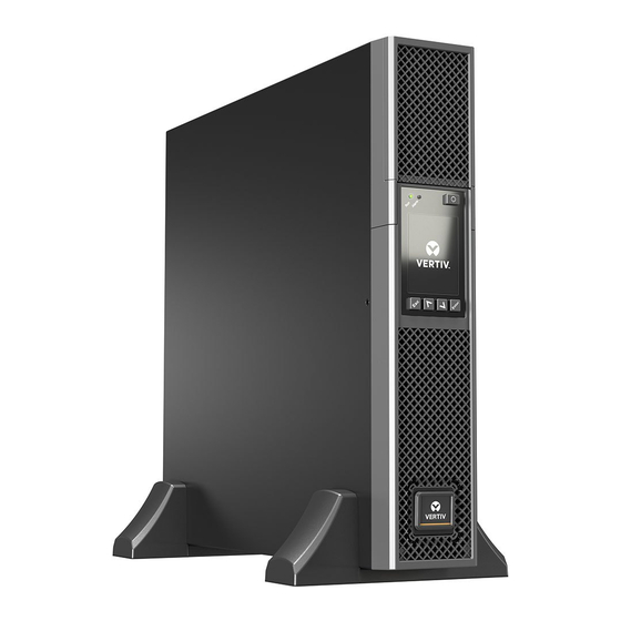
1.2. Front Panels The various GXT5 models have the same general appearance, with the main difference being the receptacle types on the rear panel� Figure 1-1 below, shows the 5-kVA to 10-kVA model in a tower and a rack configuration� Figure 1-1 Front View ITEM DESCRIPTION... -
Page 11: 1�3� Rear Panels
Output circuit-breaker reset buttons, 15-A Output cables, L6-15R USB port Terminal-block communication ports RS-232 port - RJ-45/RJ-11 connection used for command line interface RS-485 port - RJ-45 connection used for external temperature sensors Vertiv | Liebert® GXT5 | Installer/User Guide... - Page 12 Figure 1-3 GXT5-3KL630RT2UXL Rear Panel ITEM DESCRIPTION Liebert® IntelliSlot™ port Ventilation Hole External-battery-cabinet connector Input power cable, L6-30P Output circuit-breaker reset button, 20-A Output cable, L6-30R Output circuit-breakers, 15-A Output cables, L6-15R USB port Terminal-block communication ports RS-232 port - RJ-45/RJ-11 connection used for command line interface RS-485 port - RJ-45 connection used for external temperature sensors GXT5 Description...
- Page 13 Programmable outlet maintenance bypass breaker Maintenance-bypass breaker Input circuit breaker Removable junction box with knockouts for hardwire I/O L6-30R output receptacle (2x) L6-30R output breaker Programmable L6-20R output breaker Programmable L6-20R output receptacle (2x) Vertiv | Liebert® GXT5 | Installer/User Guide...
- Page 14 Figure 1-5 GXT5-6KL630RT5UXLN Rear Panel ITEM DESCRIPTION Liebert® IntelliSlot™ port Terminal-block communication connectors RS-485 port - RJ-45 connection used for external temperature sensors USB port RS-232 port - RJ-45/RJ-11 connection used for command line interface REPO connector L6-30R output breaker External-battery-cabinet connector Programmable outlet maintenance bypass breaker Programmable outlet maintenance bypass breaker...
- Page 15 Programmable outlet maintenance bypass breaker Maintenance-bypass breaker Input circuit breaker Removable junction box with knockouts for hardwire I/O L6-30R output receptacle (2x) Programmable L6-20R output breaker Programmable L6-20R output receptacle (2x) L6-30R output breaker Vertiv | Liebert® GXT5 | Installer/User Guide...
-
Page 16: 1�4� Removable Power Distribution Box
1.4. Removable Power Distribution Box The 5-kVA and 10-kVA models ship with the POD installed� The features for each POD are detailed in the following figures� Figure 1-7 PD5-CE6HDWRMBSU for GXT5-5000HVRT5UXLN ITEM DESCRIPTION POD Panel view (on rear of unit) POD inner-surface view Quick connect Figure 1-8 PD5-CE10HDWRMBSU for GXT5-8000/10KHVRT5UXLN... -
Page 17: 1�5� Internal Battery Packs
The internal battery packs for 5-10 kVA GXT5 HV models, shown in Figure 1-10 below, are located behind the access door on the front of the UPS� 3KVA models use a smaller battery pack� Figure 1-10 Internal Battery Pack ITEM. DESCRIPTION Handle Connector Vertiv | Liebert® GXT5 | Installer/User Guide... -
Page 18: 1�6� Major Internal Components And Operating Principle
1.6. Major Internal Components and Operating Principle Figure 1-11 on the next page, shows the UPS operating principle� Table 1-2 on the next page, describes the function of the major components in the UPS� NOTE: Figure 1-11 below, is one example of basic operation� The actual I/O connections for the various models may be divided into different types�... -
Page 19: 1�7� Ups States And Operating Modes
(green) is ON, the alarm indicator is OFF, and the buzzer is silent� Figure 1-12 shows the diagram of normal mode� Figure 1-12 Normal-mode Operation ITEM DESCRIPTION Mains/Utility input (by-pass input) Rectifier/PFC Inverter Battery charger Battery Bypass static switch UPS output Vertiv | Liebert® GXT5 | Installer/User Guide... -
Page 20: 1�7�2� Bypass Mode
1.7.2. Bypass Mode Bypass mode supplies power to the load from the bypass source (utility power) if an overload or fault occurs during normal operation� On the front-panel display, the run indicator (green) is ON, the alarm indicator (yellow) is ON, and the buzzer beeps once each seconds�... -
Page 21: 1�7�4� Eco Mode
UPS will transfer to Normal Mode. However, if a notification showing bypass failure or abnormal bypass voltage appears when the output is overloaded, the UPS will shut down the bypass and therefore the load will shut down. Vertiv | Liebert® GXT5 | Installer/User Guide... -
Page 22: 1�7�5� Maintenance Bypass Mode
NOTE: The UPS has no user-serviceable parts. If the UPS malfunctions and requires service, visit http://www. Vertiv.com/en-us/support/ or contact your local Vertiv representative. Figure 1-15 Maintenance Bypass-mode Operation ITEM DESCRIPTION... -
Page 23: Chapter 2: Installation
• Inspect the UPS for shipping damage� If any shipping damage is found, report it to the carrier and your local Vertiv representative immediately� • Check the accessories included against the packing list� If there is any discrepancy, contact your local Vertiv representative immediately�... -
Page 24: 2�3� Installing The Ups
2.3. Installing the UPS The UPS may be installed as a tower or in a rack, depending on available space and use considerations� Determine the type of installation and follow the appropriate instructions� See Tower Installation Rack Installation on next page�... -
Page 25: 2�4� Installing External Battery Cabinets
61. Take proper precautions when lifting them. To install the EBC(s): 1� Inspect the EBC for freight damage� Report damage to the carrier and your local dealer or Vertiv representative� 2� For tower installation: • An additional set of support-base extensions ships with each EBC�... - Page 26 Figure 2-2 EBCs connected to the UPS ITEM DESCRIPTION EBC-detection dry-contact port (See Table 2-2 page 23, for details�) EBC connector EBC-detection port External battery cabinet External battery cabinet Installation...
-
Page 27: 2�5� Installing A Power Distribution Box
Figure 2-4 on the next page, shows a diagram of the circuit breakers� Vertiv | Liebert® GXT5 | Installer/User Guide... - Page 28 Observe the following guidelines and specifications when making the hard-wire input and output connections: • Provide circuit-breaker protection according to local codes� The mains disconnect should be within sight of the UPS or have an appropriate lock-out� • Maintain service space around the UPS or use flexible conduit� •...
-
Page 29: 2�6�2� Terminal-Block Connections
Refer to the details in Terminal-block Connections page 23, when making the connections� Figure 2-4 Terminal Block 5 kVA, 8 kVA, and 10 kVA Models ITEM DESCRIPTION Output Input Vertiv | Liebert® GXT5 | Installer/User Guide... -
Page 30: 2�7� Communication Connections
2� Insert the card into the slot, and secure with the screws that held the cover plate� To make connections to the card, refer to the Installer/User Guide for the appropriate IntelliSlot card available at www�vertiv�com� 2.7.2. Connecting to the Dry-contact Port The UPS includes a dry-contact port�... - Page 31 NC, Pins 11 and 12 are opened when the fault occurs� Output 6 11, 12 Remote Fault Alert 6 Options are: • Low battery • On battery • On bypass • UPS fault (default) Vertiv | Liebert® GXT5 | Installer/User Guide...
-
Page 32: 2�7�3� Connecting A Remote Emergency Power-Off (Repo) Switch
2.7.3. Connecting a Remote Emergency Power-off (REPO) Switch The UPS includes an EPO connection in the dry-contact port� See the appropriate figure for your model in Rear Panels page 4, for the location of the port� UPS ships with a REPO jumper installed, allowing the UPS to operate as a normally-closed switch system (fail-safe)� Opening the circuit disables the UPS�... -
Page 33: 2�7�4� Connecting A Usb Cable
Power Assist from www�vertiv�com� 2.7.5. Connecting CLI Communication Cables The UPS supports the Vertiv command-line interface for operation with Vertiv ACS and other third-party monitoring protocols� The RJ-45 port (labeled “R232”) is used for CLI connection� See the appropriate figure for... - Page 34 NOTE: 8-kVA models do not support paralleling at this time. NOTE: You must use Vertiv parallel cables for the connection. NOTE: If a fault occurs during parallel-system operation, shut-off the system and make sure the cables are...
-
Page 35: 2�8�1� First-Time Start-Up Of A Parallel System
2� Wait about 30 seconds to allow the rectifier start-up to finish, then at each UPS, set the parallel parameters as follows: NOTE: If the “Parallel Comm Fail” Alarm displays, clear it and proceed. Communication should not fail after the parallel settings are synchronized. Vertiv | Liebert® GXT5 | Installer/User Guide... -
Page 36: 2�8�2� Commissioning Parallel System
• On the display, press Enter to display the Main Menu, then use the arrow buttons to select Settings, and press Enter� NOTE: To adjust the settings, you must enter a password. See Editing Display and Operation Settings page 58, for details on entering the password and editing the setting parameters. •... -
Page 37: 2�8�3� Adding A Single Ups To The Parallel System
4� On the added UPS, close the input and output breakers, wait about 30 seconds to allow the rectifier start-up to finish, then power-on the inverter� 5� Make sure that there are no alarms and that the UPS and the parallel system are operating normally� Vertiv | Liebert® GXT5 | Installer/User Guide... - Page 38 This page is intentionally left blank�...
-
Page 39: Chapter 3: Operating The Ups
8� If this is the first-time start-up of the UPS, the Start-up Guidance wizard opens to set the basic parameters of the UPS� Follow the prompts� For detailed description of UPS display functions and settings, see Operation and Display Panel page 29� Vertiv | Liebert® GXT5 | Installer/User Guide... -
Page 40: 3�3� Transferring To Battery Mode
3.3. Transferring to Battery Mode The UPS operates in Normal mode unless the mains/utility power fails or it is performing a battery self test, then it automatically transfers to Battery mode for the back-up time available or the mains/utility power is restored� Once input power is restored, the UPS returns to Normal mode�... -
Page 41: 3�6� Shutting-Down The Ups Completely
To manually power-off in an emergency, disconnect the terminal connecting the REPO port on the rear of the UPS� If mains/utility power is present, the UPS control circuit remains active even though output power is disabled� To remove all mains/utility power, disconnect the external input circuit breaker� Vertiv | Liebert® GXT5 | Installer/User Guide... - Page 42 This page is intentionally left blank�...
-
Page 43: Chapter 4: Operation And Display Panel
Run indicator LED, see LED Indicators page 39� Alarm indicator LED, see LED Indicators page 39� Power button, see Table 4-1 on the next page� Menu keys, see Table 4-1 on the next page� LCD panel� Vertiv | Liebert® GXT5 | Installer/User Guide... - Page 44 Table 4-1 Display-panel Button Functions and Descriptions BUTTON FUNCTION DESCRIPTION Enter Confirm or enter selection� Move to previous page, increase value, move left� Down Move to next page, decrease value, move right� Escape Go back� Power Power-on the UPS, power-off the UPS, transfer to Bypass Mode� NOTE: While the UPS is operating, the LCD will dim and display a screen saver if there is no active alarm or user interaction for two minutes, see Figure...
-
Page 45: 4�1� Led Indicators
Use the function keys to navigate through the menu, and view statuses or select settings in the screens� 4.2.1. Start-up and Flow Screens At start-up, the UPS executes a system test and displays the Vertiv logo screen for about 10 seconds, shown Figure 4-1 page 37�... -
Page 46: 4�2�2� Main Menu
53� About Product and network information, see About Screen page 55� Maintenance Service-only, service-password protected page for use only by Vertiv service representatives� Figure 4-4 Main Menu ITEM DESCRIPTION ECO-mode indicator Ambient Temperature Date and Time Operation and Display Panel... -
Page 47: 4�2�3� Status Screen
Input Status Options L-N voltage (V) Line-neutral voltage of input power� L-N current (A) Line-neutral current of input power� Frequency (Hz) Frequency of input of input power� Power Factor Power factor of the input power� Vertiv | Liebert® GXT5 | Installer/User Guide... - Page 48 Energy (kWh) Input power� Input black count The number times that the input voltage was lost or dropped below 60 VAC (black out)� Resets to 0 when UPS is powered down� Input brown count The number of times that the input voltage was too low to support the load and the UPS was forced to switch to battery power (brown out)�...
- Page 49 Output power� Load Status Options Sout (kVA) Apparent output power� Pout (kW) Active output power� Power Factor Power factor of output power� Load percent (%) Percentage of recent power rated to output power� Vertiv | Liebert® GXT5 | Installer/User Guide...
-
Page 50: 4�2�4� Settings Submenu
4.2.4. Settings Submenu The settings screen consists of tabs that list UPS settings for configuration and adjusting parameters with tabs for: • Output • Battery • Monitor • System NOTE: Do not change parameter settings or reset to factory defaults when powering-off the UPS. To modify UPS settings: 1�... - Page 51 • Normal = Connected load is always powered through the UPS inverter� ECO mode is disabled (default) • ECO mode = ECO mode is enabled� The UPS inverter is bypassed, and the connected load is powered by utility/mains power within the selected ECO voltage and frequency tolerances Vertiv | Liebert® GXT5 | Installer/User Guide...
- Page 52 Sets the number of attached external battery cabinets or allows the number of EBCs to be detected automatically with Autodetect� Autodetect is used only for Vertiv EBCs� If more than 6 Vertiv EBCs are connected, autodetect does not function and this must be set manually� For third-party external batteries, set this option to 0 and use “External battery AH”...
- Page 53 • Disable (default) Replace battery Activates newly-installed battery packs after replacement and reset all battery statistics for new battery packs� • Provides a confirmation window with Yes/No options to confirm replacement of batteries� Vertiv | Liebert® GXT5 | Installer/User Guide...
- Page 54 Monitor Settings Options Language Selects the language of the display, see Selecting the Display Language page 59� • English (default) • French • Portuguese • Spanish • Chinese • German • Japanese • Russian Date Selects the current date for the UPS display, YYYY-MM-DD� See Setting the Date and Time page 60�...
- Page 55 Automatically restart the UPS after an “Any mode shutdown” signal is received� When the UPS is shut down via dry-contact inputs 1 or 2, it will restart automatically if this option is enabled� • Enable • Disable (default) Vertiv | Liebert® GXT5 | Installer/User Guide...
- Page 56 Output contact NO/NC Selects the states of the dry contact outputs 5 and 6� • Normally open (default) • Normally closed Input contact NO/NC Selects the states of the dry contact inputs 1 and 2� • Normally open (default) • Normally closed� Dry contact 5 (Output) Selects the output of dry-contact 5�...
- Page 57 Sets the time of day to power off the UPS on the selected day� This option is only shown when sleep mode is enabled� • 00:00 - 23:59 (default 00:00) IT system compatibility When this option is enabled, the “Input phase reversed” and “Input ground lost” alarms are disabled� • Enable • Disable (default) Vertiv | Liebert® GXT5 | Installer/User Guide...
-
Page 58: 4�2�5� Control Screen
4.2.5. Control Screen The Control screen offers UPS-control options� To adjust the UPS controls: 1� At the main menu, select the Control icon, and press Enter� 2� Use the arrow buttons to move the cursor to the option, then press Enter to select the control� Figure 4-6 Control Screen Control Options Turn on/off/to bypass... -
Page 59: 4�2�6� Log Screen
Table 4-4 Alarm Messages MESSAGE DESCRIPTION Aux� power fault UPS internal auxiliary power voltage fault� Contact Vertiv Technical Support� Battery cabinet More than 10 external battery cabinets are connected to the UPS� Disconnect excess battery cabinets� connect abnormal The battery has reached the end of discharge and mains/utility power is unavailable� Restore the mains power� The UPS will Battery EOD power off if it is not restored�... - Page 60 The inverter is off due to DC bus voltage out of acceptable range� The load will transfer to bypass if the bypass is available DC bus abnormal because the bus voltage is outside of the acceptable range� The discharger is faulty, because the bus voltage exceeds the range when the discharger starts� Contact Vertiv Technical DC/DC fault Support�...
-
Page 61: 4�2�7� About Screen
A short has occurred on the output� Check the output cables and for any equipment that may have shorted� The rectifier is off because the bus voltage is out of the acceptable range when the rectifier starts� Contact Vertiv Technical Rectifier fault Support�... - Page 62 Figure 4-8 About Screen Tabs ITEM DESCRIPTION About screen tabs with Efficiency tab selected� Note: The tab shown in the figure is an example of the graph and does not represent the actual capacity values for your UPS model� Product Information Product Type UPS model number�...
- Page 63 Battery recommended replacement date This shows the date that it is recommend to replace the battery� It is 5 years from the time the battery was installed� SOH (%) This shows the current SOH percentage� Vertiv | Liebert® GXT5 | Installer/User Guide...
-
Page 64: 4�3� Editing Display And Operation Settings
4.3. Editing Display and Operation Settings You may adjust the display settings and UPS configuration via the LCD� The display and operation settings are password protected� The default password is 111111 (six ones)� NOTE: We recommend that you change the password to protect your system and equipment and record the new password and store it in an accessible location for later retrieval. -
Page 65: 4�3�2� Changing The Password
4� Use the down arrow to highlight Language, then press Enter� 5� Use the up/down arrows to select the language, then press Enter� All the LCD elements will now display in the selected language� Vertiv | Liebert® GXT5 | Installer/User Guide... -
Page 66: 4�3�4� Setting The Date And Time
4.3.4. Setting the Date and Time To adjust the date and time: 1� At the main menu, select the Settings icon, and press Enter� 2� At the password prompt, use the up-arrow to select the first digit, press the down-arrow to move to the next digit, repeat for each digit, then press Enter to access the settings�... -
Page 67: Chapter 5: Maintenance
• Do not lay tools or metal parts on top of batteries� • Disconnect input power prior to connecting or disconnecting battery terminals� • If the battery kit is damaged in any way or shows signs of leakage, contact your Vertiv representative immediately�... - Page 68 5� Compare the new and old battery pack to make sure they are the same type and model� If so, proceed with step 6� If they are different, stop and contact your Vertiv representative, or Technical Support, http://www� V ertiv�com/ en-us/support/�...
-
Page 69: 5�2� Charging Batteries
Log Screen page 53� 4� Check the flow screen to ensure the UPS is operating in Normal mode� If the UPS is operating in Bypass mode, contact Vertiv Technical Support� Vertiv | Liebert® GXT5 | Installer/User Guide... -
Page 70: 5�4� Cleaning The Ups
5� Check the flow screen to see if batteries are discharging (operating in Battery mode) while utility power is normal� If so, contact Vertiv Technical Support� 5.4. Cleaning the UPS WARNING! Risk of electric shock Can cause injury or death. Disconnect all local and remote electric power supplies before working with the UPS. - Page 71 Figure 5-2 below, shows an example on the 5-kVA model. Figure 5-2 Maintenance-bypass Breaker Cover and Captive Screws ITEM DESCRIPTION Captive screws for POD Connector-cover screws Maintenance-bypass breaker Programmable outlet maintenance bypass breaker Vertiv | Liebert® GXT5 | Installer/User Guide...
-
Page 72: 5�6� Firmware Updates
The name and password may have been changed from the default. NOTE: For detailed operating instructions for the card, refer to the Liebert® IntelliSlot™ RDU101 Communications Card Installer/User Guide, available at www.Vertiv.com. Updating MCU Firmware via RDU101 NOTE: Do not update firmware while the UPS is on Battery mode. - Page 73 You can check the firmware version, select the System folder in the tab-menu pane on the left-hand side of the page, and check the Firmware Version field, see Figure 5-4 on the next page� Vertiv | Liebert® GXT5 | Installer/User Guide...
- Page 74 Figure 5-3 File Transfer on the RDU101 User Interface ITEM DESCRIPTION "UPS" tab, typically the UPS model number File Transfer folder Choose File button Transfer File button Status of file transfer Figure 5-4 Firmware Version on the RDU101 User Interface Maintenance...
-
Page 75: 5�7� Updating Dsp Firmware Via Rdu101
On the file-transfer page, click Choose File, and select the DSP upgrade file, then click Transfer file� c� Enter the Username and Password, then click Login� The factory-defaults: Username : Liebert (case-sensitive) Password: Liebert (case-sensitive) Vertiv | Liebert® GXT5 | Installer/User Guide... - Page 76 NOTE: The name and password may have been changed from the default. Be sure to obtain the user name and password from an administrator. The status of the transfer displays in the File Transfer Status section� After about 2 minutes, the UPS restarts and the web page refreshes�...
-
Page 77: 5�8� Updating Firmware With A Cli Connection
Figure 5-7 Firmware Version on the RDU101 User Interface 5.8. Updating Firmware with a CLI Connection You can use the Vertiv command-line interface to update firmware with a computer connected to the R232 (RJ- 45) port on the rear of the UPS�... - Page 78 • Select 115200 for the connection speed� • Open the emulator session� 4� On the CLI, enter the username and password: • Default username = user • Default password = 123456 5� On the command line, enter update, then press d on the keyboard, see Figure 5-8 on the next page 6�...
- Page 79 The status of the transfer displays in a status dialog� After about 2 minutes, the UPS restarts and the CLI exits update mode� NOTE: The transfer process takes about 2 minutes. Do not close the status dialog. a� You can check the firmware version by entering status system in the command line� Vertiv | Liebert® GXT5 | Installer/User Guide...
- Page 80 Figure 5-10 File Transfer with the CLI Maintenance...
-
Page 81: Chapter 6: Troubleshooting
NOTE: When an alarm is indicated, an alarm message is logged. Table 4-4 page 42, describes the alarm messages you may see. When a fault is indicated, front-panel display list the fault, which are described in Table below. Vertiv | Liebert® GXT5 | Installer/User Guide... -
Page 82: 6�2�1� Faults
Vertiv Technical Support� Visit the GXT5 product page at www�vertiv�com for contact information� When reporting a UPS issue to Vertiv, include the UPS model and serial number� These are located in several places for your ease of location: • On the top panel (rack mount orientation) •... -
Page 83: Chapter 7: Specifications
Battery Mfr�/Part # LEOCH DJW12-9�0 Back-up time Battery Run Times page 81� Upper-limit selections +10%, +15%, +20%; default +10%� Lower-limit selections -10%, -15%, -20%; default -15% Disable-bypass operation When the input frequency prevents synchronous operation Vertiv | Liebert® GXT5 | Installer/User Guide... - Page 84 Table 7-1 UPS Specifications, 5-kVA to 10-kVA models (continued) MODEL GXT5- 5000HVRT5UXLN 8000HVRT5UXLN 10KHVRT5UXLN RATING 5000 VA/5000 W 8000 VA/8000 W 10000 VA/10000 W Environmental Operating Temperature, °F (°C) 32 to 104 (0 to 40) (no derating) Storage Temperature, °F (°C) 5 to 104 (–15 to 40) Relative Humidity 0 –...
- Page 85 EN 62040-2:2006 EN61000-4-2 EN 61000-3-2:2014 EN61000-4-3 EN 61000-3-3:2013 EN61000-4-4 Transportation ISTA Procedure 1A ISTA Procedure 1E ANSI C62�41 Category B (6kV/3kA) Surge Immunity IEC 61000-4-5 RFI/EMI CISPR22 Class A FCC Part 15 (Class A) Vertiv | Liebert® GXT5 | Installer/User Guide...
- Page 86 Table 7-3 Power-distribution Specifications PD5-CE6HDWRMBS PD5-CE10HDWRMBS MODEL NUMBER PD5-CE6HDWRMBSU PD5-CE10HDWRMBSU Amp Rating 50 A 63 A Input Power Connection Single-phase (L1-L2-G) hard-wired Output Power Connection Single-phase (L1-L2-G) hard-wired Two IEC320 C19 16A/250V Sockets Four IEC320 C19 16A/250V Sockets, Includes Six C13 10A/250V Sockets Four C13 10A/250V Sockets Input Branch Circuit Breaker, 50 A...
-
Page 87: 7�1� Battery Run Times
103�7 129�1 154�0 180�3 205�0 231�3 258�2 2700 2700 4�0 22�2 43�1 67�0 89�3 113�6 136�7 159�4 181�7 203�7 226�8 3000 3000 3�3 19�1 38�7 57�9 80�9 101�5 121�0 137�8 157�2 177�0 196�7 Vertiv | Liebert® GXT5 | Installer/User Guide... - Page 88 Table 7-7 Battery Run Time in Minutes Model: GXT5-5000HVRT5UXLN NUMBER OF EXTERNAL BATTERY CABINETS INTERNAL LOAD BATTERY ONLY Minutes 120�0 272�5 427�5 582�5 737�5 892�5 1047�5 1202�5 1357�5 1512�5 1667�5 1000 1000 59�0 129�0 211�0 294�0 377�0 460�0 543�0 625�5 708�5 791�5 874�5...
- Page 89 36�0 45�5 55�5 64�5 74�0 83�5 93�0 9000 9000 2�5 8�0 15�0 22�5 30�5 39�5 48�0 56�5 65�0 73�0 81�5 10000 10000 2�0 7�0 13�0 19�5 26�5 34�5 42�0 50�0 57�5 65�0 72�5 Vertiv | Liebert® GXT5 | Installer/User Guide...
- Page 90 This page is intentionally left blank�...
-
Page 91: Appendix I: Open Source Software Legal Notices
Appendix I: Open Source Software Legal Notices The GXT5 product links the FreeRTOS software with Vertiv Group Corporation’s proprietary modules that communicate with the FreeRTOS software solely through the FreeRTOS API interface� This use is an exception to the FOSS GPLv2 license� The user is free to redistribute the FreeRTOS software and/or modify it under the terms of the GNU General Public License as published by the Free Software Foundation�... - Page 92 This page is intentionally left blank�...
-
Page 93: Appendix Ii: Technical Support
Toll +39 02 98250222 In the United States Technical support e: liebert�upstech@vertiv�com p: 1-800-222-5877 menu option 1 Monitoring support e: liebert�monitoring@vertiv�com p: 1-800-222-5877 menu option 2 Warranty support e: microups�warranty@vertiv�com p: 1-800-222-5877 menu option 3 Vertiv | Liebert® GXT5 | Installer/User Guide... - Page 94 © 2020 Vertiv Group Corp. All rights reserved. Vertiv™ and the Vertiv logo are trademarks or registered marks of Vertiv Group Corp. All other names and logos referred to are trade names, trademarks, or registered trademarks of their respective owners. While every precaution has been taken to ensure accuracy and completeness herein.
Need help?
Do you have a question about the Liebert GXT5-5000MVRT4UXLN and is the answer not in the manual?
Questions and answers