Grizzly G0568 Owner's Manual
24" industrial bandsaw
Hide thumbs
Also See for G0568:
- User manual (17 pages) ,
- Machine data sheet (2 pages) ,
- Instruction manual (88 pages)
Table of Contents
Advertisement
Quick Links
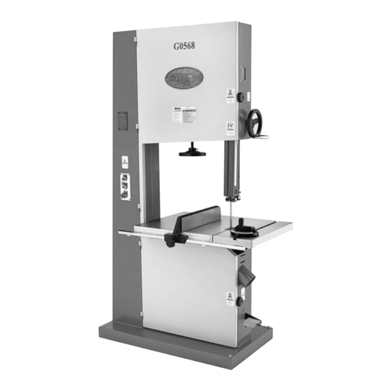
MODEL G0568/G0569
24" INDUSTRIAL BANDSAW
OWNER'S MANUAL
(For models manufactured since 10/11)
COPYRIGHT © AUGUST, 2004 BY GRIZZLY INDUSTRIAL, INC. REVISED JUNE, 2018 (MN)
WARNING: NO PORTION OF THIS MANUAL MAY BE REPRODUCED IN ANY SHAPE
OR FORM WITHOUT THE WRITTEN APPROVAL OF GRIZZLY INDUSTRIAL, INC.
V2.06.18
CA6450# PRINTED IN TAIWAN
Advertisement
Table of Contents

Related Manuals for Grizzly G0568


Summary of Contents for Grizzly G0568
- Page 1 OWNER'S MANUAL (For models manufactured since 10/11) COPYRIGHT © AUGUST, 2004 BY GRIZZLY INDUSTRIAL, INC. REVISED JUNE, 2018 (MN) WARNING: NO PORTION OF THIS MANUAL MAY BE REPRODUCED IN ANY SHAPE OR FORM WITHOUT THE WRITTEN APPROVAL OF GRIZZLY INDUSTRIAL, INC.
- Page 2 This manual provides critical safety instructions on the proper setup, operation, maintenance, and service of this machine/tool. Save this document, refer to it often, and use it to instruct other operators. Failure to read, understand and follow the instructions in this manual may result in fire or serious personal injury—including amputation, electrocution, or death.
-
Page 3: Table Of Contents
Foot Brake ........... 40 Identification ........... 3 Key Switch ........... 40 Controls & Components ......... 4 Guide Post ........... 41 G0568 Machine Data Sheet ......7 Ripping ............41 G0569 Machine Data Sheet ......9 Crosscutting ..........42 Resawing ............. 42 SECTION 1: SAFETY ........ -
Page 4: Introduction
Blade guides on both sides of the cutting area keep the blade from flexing or being pushed off the wheels from the horizontal pressure of the workpiece while cutting. Model G0568/G0569 (Mfd. Since 10/11) -
Page 5: Identification
Identification Figure 2. G0568 rear, top-side of the bandsaw. M. Guide Post Lock Knob N. Blade Tension Lever O. Blade Tracking Knob Figure 1. G0658 front view. A. Blade Tension Indicator B. Key Switch, Start & Stop Buttons C. Rip Fence D. -
Page 6: Controls & Components
Twist clockwise to reset. H. Tracking Control Knob: Adjusts tilt position of upper wheel to set/control blade tracking (refer to Page 25 for more information). Tracking Control Lock Lever: Secures position of blade tracking control knob. Model G0568/G0569 (Mfd. Since 10/11) -
Page 7: Guide Post
O. Foot Brake: Stops blade wheels and turns motor OFF. IMPORTANT: After the foot brake is pressed, press the ON button to restart the machine. The Emergency Stop button does not have to be reset. Model G0568/G0569 (Mfd. Since 10/11) - Page 8 U. Miter Gauge: Typically used for cross cuts. Adjustable from 0°–60° left or right, and has R. Table Tilt Handwheel: Adjusts angle of table stops at 45°L and 45°R. tilt. V. Fence Lock Handle: Secures fence position. Model G0568/G0569 (Mfd. Since 10/11)
-
Page 9: G0568 Machine Data Sheet
MACHINE DATA SHEET Customer Service #: (570) 546-9663 · To Order Call: (800) 523-4777 · Fax #: (800) 438-5901 MODEL G0568 24" INDUSTRIAL BANDSAW 5 HP SINGLE‐ PHASE Product Dimensions: Weight................................836 lbs. Width (side-to-side) x Depth (front-to-back) x Height..............48 x 32 x 83-1/2 in. - Page 10 The information contained herein is deemed accurate as of 6/19/2018 and represents our most recent product specifications. Model G0568 PAGE 2 OF 3 Due to our ongoing improvement efforts, this information may not accurately describe items previously purchased. Model G0568/G0569 (Mfd. Since 10/11)
-
Page 11: G0569 Machine Data Sheet
The information contained herein is deemed accurate as of 6/19/2018 and represents our most recent product specifications. Model G0569 PAGE 1 OF 3 Due to our ongoing improvement efforts, this information may not accurately describe items previously purchased. Model G0568/G0569 (Mfd. Since 10/11) - Page 12 The information contained herein is deemed accurate as of 6/19/2018 and represents our most recent product specifications. Model G0569 PAGE 2 OF 3 Due to our ongoing improvement efforts, this information may not accurately describe items previously purchased. -10- Model G0568/G0569 (Mfd. Since 10/11)
-
Page 13: Section 1: Safety
Everyday ery. Never operate under the influence of drugs or eyeglasses are NOT approved safety glasses. alcohol, when tired, or when distracted. -11- Model G0568/G0569 (Mfd. Since 10/11) - Page 14 EXPERIENCING DIFFICULTIES. If at any time debris. Make sure they are properly installed, you experience difficulties performing the intend- undamaged, and working correctly BEFORE ed operation, stop using the machine! Contact our operating machine. Technical Support at (570) 546-9663. -12- Model G0568/G0569 (Mfd. Since 10/11)
-
Page 15: Additional Safety For Bandsaws
DO NOT try to stop or slow blade with your This machine is NOT designed to cut metal, hand or the workpiece. glass, stone, tile, etc. -13- Model G0568/G0569 (Mfd. Since 10/11) -
Page 16: Section 2: Power Supply
To reduce the risk of these hazards, avoid over- Current Carrying Prongs loading the machine during operation and make sure it is connected to a power supply circuit that Figure 12. Typical L6-30 plug and receptacle. meets the specified circuit requirements. -14- Model G0568/G0569 (Mfd. Since 10/11) -
Page 17: Extension Cords
(isolated) from the power supply when required. This installation must be performed by an electrician in accordance with all applicable electrical codes and ordinances. -15- Model G0568/G0569 (Mfd. Since 10/11) -
Page 18: 440V Conversion
Disconnect Switch power source. If, at any time during this procedure Power you need help, call Grizzly Tech Support at (570) Source Machine 546-9663. To rewire the Model G0569 for 440V operation:... -
Page 19: Section 3: Setup
Use this and have resolved any issues between Grizzly or the other machinery with caution and respect. shipping agent. You MUST have the original pack- Failure to do so could result in serious per- aging to file a freight claim. -
Page 20: Inventory
Open End Wrench 17 x 19 ......1 tic bags and packing materi- Miter Gauge ..........1 als to eliminate choking/suf- K. Handwheel Handle ........1 focation hazards for children and animals. Figure 16. Main inventory. -18- Model G0568/G0569 (Mfd. Since 10/11) -
Page 21: Hardware Recognition Chart
Hardware Recognition Chart USE THIS CHART TO MATCH UP HARDWARE DURING THE INVENTORY AND ASSEMBLY PROCESS. Flat Head Screw -19- Model G0568/G0569 (Mfd. Since 10/11) -
Page 22: Cleanup
Figure 18. T23692 Orange Power Degreaser. Repeat Steps 2–3 as necessary until clean, then coat all unpainted surfaces with a quality metal protectant to prevent rust. -20- Model G0568/G0569 (Mfd. Since 10/11) -
Page 23: Site Considerations
Only install in an Shadows, glare, or strobe effects that may distract access restricted location. or impede the operator must be eliminated. 30" 47" Figure 19. Minimum working clearances. -21- Model G0568/G0569 (Mfd. Since 10/11) -
Page 24: Lifting & Placing
Note: If you are concerned about your forklift forks hitting the tension handwheel, remove the handwheel before positioning the forks, then rein- stall it after lifting. Figure 20. Lifting the bandsaw. Remove pallet and slowly set bandsaw into position. -22- Model G0568/G0569 (Mfd. Since 10/11) -
Page 25: Anchoring To Floor
Riser blocks, shown in Figure 23, are included Diameter of Mounting Hardware ....⁄ " with the Model G0568/G0569 to match the height of the table to your personal preference or needs. This added feature, when installed, lifts the work- Anchoring machinery to the floor prevents tipping ing table height from 32 "... -
Page 26: Assembly
Handle Hex Nut Figure 26. Handwheel correctly installed. Figure 24. Fence handle components. Tighten the cap screw in the handwheel securely. Thread the handle in to the handwheel and tighten with the 14mm wrench. -24- Model G0568/G0569 (Mfd. Since 10/11) -
Page 27: Dust Collection
Tug each hose to make sure it does not come are adjusted away from the blade (see Page off. Note: A tight fit is necessary for proper 34). performance. Figure 27. Dust hoses attached to dust port. -25- Model G0568/G0569 (Mfd. Since 10/11) - Page 28 Be careful when turning the wheels by NOTICE hand. Changes in the blade tension may change the blade tracking. -26- Model G0568/G0569 (Mfd. Since 10/11)
-
Page 29: Power Connection
Only: Shut off the main power at the power source circuit breaker and attach the wires to the locking shut-off switch. Model G0569 3-Phase, 220V Operation: Connect the power cord with an L15-30 plug to an L15-30 receptacle. -27- Model G0568/G0569 (Mfd. Since 10/11) -
Page 30: Test Run
3) the stop button safety feature works correctly. Figure 32. G0568 switch disabling key and ON/ If, during the test run, you cannot easily locate OFF switch. the source of an unusual noise or vibration, stop Press the OFF button to stop the machine. - Page 31 Stop the machine, disconnect the power source, then swap any two of the three power wires that connect to the machine. Figure 34. Upper door limit switch. -29- Model G0568/G0569 (Mfd. Since 10/11)
-
Page 32: Adjusting Table Stop
Align the tip of the pointer with the 0˚ mark on lever. the table tilt scale, then tighten the screw to secure the setting. -30- Model G0568/G0569 (Mfd. Since 10/11) -
Page 33: Aligning Table
Figure 38. Cap screws securing table to trun- nion. Place an accurate straightedge along the blade. The straightedge should lightly touch both the front and back of the blade. Note: Make sure the straightedge does not go across a tooth. -31- Model G0568/G0569 (Mfd. Since 10/11) -
Page 34: Aligning Fence
31). Mount the fence next to the miter slot, then loosen the hex bolts, lock washers, and flat washers that secure the fence rail to the table. -32- Model G0568/G0569 (Mfd. Since 10/11) -
Page 35: Pointer Calibration
Loosen the screw that secures the angle pointer and adjust the pointer to the 0˚ mark on the scale. Retighten the screw that secures the angle pointer. Figure 42. Fence pointer adjustment screw. Tighten the pointer adjustment screw. -33- Model G0568/G0569 (Mfd. Since 10/11) -
Page 36: Tensioning Blade
Page 25). DISCONNECT BANDSAW FROM POWER! Turn the bandsaw ON. Slowly release the tension one quarter of a turn at a time. When you see the bandsaw blade start to flutter, stop decreasing the tension. -34- Model G0568/G0569 (Mfd. Since 10/11) - Page 37 -35- Model G0568/G0569 (Mfd. Since 10/11)
-
Page 38: Adjusting Support Bearings
Note: The lateral adjustment rod screw and guide block assembly screws are located Support Bearing below the table tilt lock lever (see Figure 48). Figure 49. Illustration of blade set perpendicular (90˚) to the support bearing face. -36- Model G0568/G0569 (Mfd. Since 10/11) - Page 39 0.016" away from the back of the blade, as locked in place. illustrated in Figure 50, or use a dollar bill, as shown in Figure 51. Tighten the bolt to keep the support bearing locked in place. -37- Model G0568/G0569 (Mfd. Since 10/11)
-
Page 40: Section 4: Operations
Read books/magazines or get formal training before beginning any proj- ects. Regardless of the content in this sec- tion, Grizzly Industrial will not be held liable for accidents caused by lack of training. -38- Model G0568/G0569 (Mfd. Since 10/11) -
Page 41: Workpiece Inspection
On the contrary, a workpiece supported on the bowed side will rock during a cut and could cause kickback or severe injury. -39- Model G0568/G0569 (Mfd. Since 10/11) -
Page 42: Foot Brake
Foot Brake Key Switch The Model G0568/G0569 is equipped with a foot One of the most useful safety features of the brake (see Figure 53). Use the brake only in Model G0568/G0569 is the key switch (see Figure 54). To disable the ON and OFF controls emergency situations to disconnect power to the motor and bring the blade to a halt. -
Page 43: Guide Post
In the event that something unexpected happens, your hands or fingers may slip into the blade. ALWAYS use a push stick when ripping narrow pieces. Failure to fol- low these warnings may result in serious personal injury! -41- Model G0568/G0569 (Mfd. Since 10/11) -
Page 44: Crosscutting
Figure 57. Example of crosscutting operation pressure against the fence and table, and with miter gauge. slowly feed the workpiece into the moving blade until the blade is completely through the workpiece (see Figure 58). -42- Model G0568/G0569 (Mfd. Since 10/11) -
Page 45: Cutting Curves
'' ........⁄ Repeat Steps 1-4 until the blade cuts ⁄ '' ........1 ⁄ straight. ⁄ '' ........2 ⁄ ⁄ '' ........3 ⁄ Tighten the table bolts. ⁄ '' ........5 ⁄ -43- Model G0568/G0569 (Mfd. Since 10/11) -
Page 46: Stacked Cuts
Secure the table tilt lock lever. Follow "Positive Stop" instructions on Page Figure 61. Typical stacked cut. 30 for resettting the stop bolt and table for horizontal (0º) operations. -44- Model G0568/G0569 (Mfd. Since 10/11) -
Page 47: Blade Information
When selecting blades, another option to con- the distance between wheels. The Model G0568/ sider is the shape, gullet size, teeth set and teeth G0569 is designed for blades that are 179"–182"... -
Page 48: Blade Breakage
Dirty or gummed up blades pass through the cutting material with much more resistance • Continuously running the bandsaw when not than clean blades. This extra resistance also in use. causes unnecessary heat. -46- Model G0568/G0569 (Mfd. Since 10/11) -
Page 49: Blade Changes
Adjust tension as described on Page 34. wheels. Adjust tracking if needed (see Page 25). Slide the blade through the slot in the table. Adjust the upper/lower guide bearings and the support bearings (see Page 34). Close the wheel covers. -47- Model G0568/G0569 (Mfd. Since 10/11) -
Page 50: Section 5: Accessories
T20451—"Kirova" Clear Safety Glasses To reduce this risk, only install accessories T20452—"Kirova" Anti-Reflective S. Glasses recommended for this machine by Grizzly. T20456—DAKURA Safety Glasses, Black/Clear NOTICE T20502 Refer to our website or latest catalog for additional recommended accessories. - Page 51 Base must be replaced with the D2246A Extension gauge and adjusts the angle of cut to the scribed line, ensuring a uniform thickness without put- Bars to accommodate the length of the G0568 G0569 bandsaws. ting undue strain on the blade. This includes the ⁄...
-
Page 52: Section 6: Maintenance
Clean the components in this section with an oil/ grease solvent cleaner or mineral spirits before applying lubrication. Cleaning the Model G0568/G0569 is relatively easy. Vacuum excess wood chips and sawdust, All bearings are sealed and permanently lubri- and wipe off the remaining dust with a dry cloth. - Page 53 Apply a thin coat of light all-purpose grease to the rack. Move the blade guide up and down several Figure 72. Tension adjustment assembly times and remove any excess grease to help locations (top wheel removed for clarity). prevent sawdust buildup. -51- Model G0568/G0569 (Mfd. Since 10/11)
- Page 54 Move the table down and then back up to dis- tribute the grease, then wipe off any excess grease from the trunnions. Figure 73. Example of lubricating table tilt rack and pinion assembly. -52- Model G0568/G0569 (Mfd. Since 10/11)
-
Page 55: Section 7: Service
8. Motor connection wired incorrectly. 8. Wire motor correctly. Refer to inside junction box cover or Page 65 (G0568) or Page 66 (G0569). 9. Test all legs for power, test field coil, and fix contacts 9. Contactor has poor contacts or is at fault. - Page 56 2. Positive stop bolt not set correctly. Table does not tilt 1. Pointer or scale calibrated incorrectly. 1. Calibrate pointer/scale at true 45 degrees. to 45 degrees. 2. Machine component blocking path. 2. Remove component blocking table. -54- Model G0568/G0569 (Mfd. Since 10/11)
- Page 57 1. Clogged dust port. 1. Clean out dust port. inside cabinet. 2. Low CFM (airflow) from dust collection 2. Repair ducting for leaks or clogs, move dust collector system. closer to machine, install a stronger dust collector. -55- Model G0568/G0569 (Mfd. Since 10/11)
- Page 58 8. Fence or miter slot out of alignment with 8. Align table miter slot and fence with blade. blade. 9. Blade guide alignment at fault. 9. Adjust blade guide bearings for correct blade support. -56- Model G0568/G0569 (Mfd. Since 10/11)
-
Page 59: Checking And Tensioning V-Belts
If the deflection is more than ⁄ ", repeat Step 4. When the V-belt tension is correct, tighten the motor adjustment bolts, and close the wheel covers. Deflection Bandsaw Wheel Figure 75. V-belt deflection. -57- Model G0568/G0569 (Mfd. Since 10/11) -
Page 60: Replacing V-Belt
Tighten the bolt/nuts to secure each brush in V-belts over the motor pulley, and turn the place. tension bolt clockwise to tighten the V-Belt tension. When the tension is correct, tighten the motor hinge bolt and close the lower wheel cover. -58- Model G0568/G0569 (Mfd. Since 10/11) -
Page 61: Adjusting Tension Lever
Adjust the table square with the blade using the table tilt handwheel, then secure it with the table tilt lock lever. Figure 79. Example of quick release tension lever adjustment screw. Tighten the jam nut. -59- Model G0568/G0569 (Mfd. Since 10/11) - Page 62 Go to Step 7. Remove the screws that secure the guide post guard and move it up and out of the way. -60- Model G0568/G0569 (Mfd. Since 10/11)
- Page 63 —If the measurements are not equal, con- tinue adding shims as needed until guide post rack to blade distance is the same at the top and bottom. Reinstall the guide post guard with the screws removed in Step 3. -61- Model G0568/G0569 (Mfd. Since 10/11)
-
Page 64: Wheel Alignment
Wheels used during operation. Adjustment Place your gauge up against both wheels in the positions shown in Figure 86. Figure 86. Checking for coplanarity. -62- Model G0568/G0569 (Mfd. Since 10/11) - Page 65 Tilt Tilt Bottom Tilt Figure 87. Lower wheel adjustment control. Parallel, Not Not Parallel Adjust Coplanar Coplanar Not Coplanar Tracking Knob Coplanarity Gauge Contacts Top And Bottom of Both Wheels Figure 88. Coplanarity diagram. -63- Model G0568/G0569 (Mfd. Since 10/11)
-
Page 66: Section 8: Wiring
Technical Support at (570) 546-9663. The photos and diagrams included in this section are best viewed in color. You can view these pages in color at www.grizzly.com. -64- Model G0568/G0569 (Mfd. Since 10/11) -
Page 67: G0568 Wiring Diagram
CONTROL PANEL (viewed from behind) L1/1 L2/3 NO13 L3/5 NC15 MA-18 NC16 T1/2 T2/4 T3/6 NO14 MAG SWITCH MOTOR Start Ground Capacitor 300MFD FOOT BRAKE 250VAC Capacitor 45UF 450VAC READ ELECTRICAL SAFETY -65- Model G0568/G0569 (Mfd. Since 10/11) ON PAGE 64! -
Page 68: G0569 Wiring Diagram 220V
LIMIT SWITCH (NC) Ground CONTROL PANEL (viewed from behind) L1/1 L2/3 L3/5 NO13 NC15 MA-18 NC16 NO14 T1/2 T2/4 T3/6 MAG SWITCH FOOT BRAKE W1 W5 V1 V5 Ground READ ELECTRICAL SAFETY -66- Model G0568/G0569 (Mfd. Since 10/11) ON PAGE 64! -
Page 69: G0569 Wiring Diagram 440V
(if used) LIMIT SWITCH (NC) Ground CONTROL PANEL (viewed from behind) L1/1 L2/3 NO13 L3/5 NC15 MA-18 NC16 T1/2 T2/4 T3/6 NO14 MAG SWITCH FOOT BRAKE Ground READ ELECTRICAL SAFETY -67- Model G0568/G0569 (Mfd. Since 10/11) ON PAGE 64! -
Page 70: Section 9: Parts
SECTION 9: PARTS Main G0568 G0569 G0568 23V3-1 23V3-6 23V3-5 23V3-2 23V3-7 23V3-8 23V3-10 23V3-3 23V3-9 23V3-11 23V3-4 G0569 23-7 23-1 23-2 BUY PARTS ONLINE AT GRIZZLY.COM! -68- Model G0568/G0569 (Mfd. Since 10/11) Scan QR code to visit our Parts Store. -
Page 71: Main Parts List
P0568061 COMPRESSION SPRING 1 X 8 X 40 P0568022 CORD CLAMP 1/2" P0568062 ROLL PIN 3 X 12 23V3 P0568023V3 MOTOR 5HP 220V 1-PH V3.07.13 (G0568) P0568063 MOVING PLATE 23V3-1 P0568023V3-1 FAN COVER P0568064 TAP SCREW M4 X 10 23V3-2... - Page 72 RISER BAR P0568129 BALL BEARING 6306-2RS P0568322 PRESS PLATE P0568130 LOWER WHEEL 25" P0568323 PHLP HD SCR M6-1 X 8 P0568131 BUSHING BUY PARTS ONLINE AT GRIZZLY.COM! -70- Model G0568/G0569 (Mfd. Since 10/11) Scan QR code to visit our Parts Store.
-
Page 73: Table
FLAT WASHER 8MM P0568169 MICRO ADJUSTING RING P0568332 LOCK WASHER 8MM P0568170 CAP SCREW M8-1.25 X 20 P0568333 HEX BOLT M8-1.25 X 20 BUY PARTS ONLINE AT GRIZZLY.COM! -71- Model G0568/G0569 (Mfd. Since 10/11) Scan QR code to visit our Parts Store. -
Page 74: Guide Post
CAP SCREW M8-1.25 X 20 P0568246 PINION GEAR 15T P0568215 LOCK WASHER 8MM P0568287 SET SCREW M5-.8 X 5 P0568216 SUPPORT PLATE BUY PARTS ONLINE AT GRIZZLY.COM! -72- Model G0568/G0569 (Mfd. Since 10/11) Scan QR code to visit our Parts Store. -
Page 75: Blade Guides
SUPPORT BRACKET V2.09.06 P0568261 SET SCREW M6-1 X 10 P0568280 HEX BOLT M6-1 X 16 262A P0568262A UPPER SPACING SLEEVE V2.12.05 BUY PARTS ONLINE AT GRIZZLY.COM! -73- Model G0568/G0569 (Mfd. Since 10/11) Scan QR code to visit our Parts Store. -
Page 76: Label Placement
3. Always wear approved eye protection and respirator. Blade Length: 181" 4. Properly ground machine—connect to permanently grounded WITHOUT WRITTEN APPROVAL! Grizzly will not accept labels changed without approval. Blade Width Range: 1/4" – 1-1/2" metal wiring system or an equipment-grounding conductor. -
Page 77: Warranty Card
Would you recommend Grizzly Industrial to a friend? _____ Yes _____No Would you allow us to use your name as a reference for Grizzly customers in your area? Note: We never use names more than 3 times. _____ Yes _____No 10. - Page 78 FOLD ALONG DOTTED LINE Place Stamp Here GRIZZLY INDUSTRIAL, INC. P.O. BOX 2069 BELLINGHAM, WA 98227-2069 FOLD ALONG DOTTED LINE Send a Grizzly Catalog to a friend: Name_______________________________ Street_______________________________ City______________State______Zip______ TAPE ALONG EDGES--PLEASE DO NOT STAPLE...
-
Page 79: Warranty & Returns
WARRANTY & RETURNS Grizzly Industrial, Inc. warrants every product it sells for a period of 1 year to the original purchaser from the date of purchase. This warranty does not apply to defects due directly or indirectly to misuse, abuse, negligence, accidents, repairs or alterations or lack of maintenance.
Need help?
Do you have a question about the G0568 and is the answer not in the manual?
Questions and answers