Grizzly G0561 Owner's Manual
7" x 12" metal cutting bandsaw
Hide thumbs
Also See for G0561:
- Owner's manual (52 pages) ,
- Owner's manual (52 pages) ,
- Owner's manual (60 pages)
Table of Contents
Advertisement
Quick Links
MODEL G0561
7" x 12" METAL CUTTING BANDSAW
OWNER'S MANUAL
(For models manufactured since 01/08)
COPYRIGHT © MAY, 2006 BY GRIZZLY INDUSTRIAL, INC., REVISED JULY, 2015 (MN)
WARNING: NO PORTION OF THIS MANUAL MAY BE REPRODUCED IN ANY SHAPE
OR FORM WITHOUT THE WRITTEN APPROVAL OF GRIZZLY INDUSTRIAL, INC.
#PC8297 PRINTED IN CHINA
V2.11.14
Advertisement
Table of Contents

Related Manuals for Grizzly G0561


Summary of Contents for Grizzly G0561
- Page 1 OWNER'S MANUAL (For models manufactured since 01/08) COPYRIGHT © MAY, 2006 BY GRIZZLY INDUSTRIAL, INC., REVISED JULY, 2015 (MN) WARNING: NO PORTION OF THIS MANUAL MAY BE REPRODUCED IN ANY SHAPE OR FORM WITHOUT THE WRITTEN APPROVAL OF GRIZZLY INDUSTRIAL, INC.
- Page 2 This manual provides critical safety instructions on the proper setup, operation, maintenance, and service of this machine/tool. Save this document, refer to it often, and use it to instruct other operators. Failure to read, understand and follow the instructions in this manual may result in fire or serious personal injury—including amputation, electrocution, or death.
-
Page 3: Table Of Contents
Wiring Safety Instructions ......46 Inventory ............13 Electrical Components ......... 47 Cleanup ............14 G0561 110V & 220V Wiring Diagrams ..48 Site Considerations ........15 SECTION 9: PARTS ........49 Shipping Bracket .......... 16 Cabinet & Base ..........49 Work Stop ............ -
Page 4: Introduction
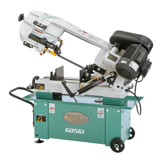
INTRODUCTION Machine Description Manual Accuracy The Model G0561 Metal Cutting Bandsaw has We are proud to provide a high-quality owner’s a flexible continuous blade that is used to make manual with your new machine! straight cuts in metal stock. We made every effort to be exact with the instruc- The clamping vise adjusts for cuts between 0°... -
Page 5: Identification
Motor ON/OFF Switch D. Blade Guides Vise Handwheel E. 1 HP Motor K. Automatic Shut-Off Tab Feed Rate Control Knob Blade Tracking Controls To reduce your risk of serious injury, read this entire manual BEFORE using machine. Model G0561 (Mfd. Since 01/08) -
Page 6: Machine Data Sheet
MACHINE DATA SHEET Customer Service #: (570) 546-9663 · To Order Call: (800) 523-4777 · Fax #: (800) 438-5901 MODEL G0561 7" X 12" METAL CUTTING BANDSAW Product Dimensions: Weight................................330 lbs. Width (side-to-side) x Depth (front-to-back) x Height................48 x 16 x 40 in. - Page 7 The information contained herein is deemed accurate as of 7/10/2017 and represents our most recent product specifications. Model G0561 PAGE 2 OF 2 Due to our ongoing improvement efforts, this information may not accurately describe items previously purchased. Model G0561 (Mfd. Since 01/08)
-
Page 8: Section 1: Safety
Everyday ery. Never operate under the influence of drugs or eyeglasses are NOT approved safety glasses. alcohol, when tired, or when distracted. Model G0561 (Mfd. Since 01/08) - Page 9 EXPERIENCING DIFFICULTIES. If at any time debris. Make sure they are properly installed, you experience difficulties performing the intend- undamaged, and working correctly BEFORE ed operation, stop using the machine! Contact our operating machine. Technical Support at (570) 546-9663. Model G0561 (Mfd. Since 01/08)
-
Page 10: Additional Safety For Metal Bandsaws
No list of safety guidelines can be complete. Every shop environment is different. Like all machines there is danger associated with the Model G0561. Accidents are frequently caused by lack of familiarity or failure to pay attention. Use this machine with respect and caution to lessen the possibility of operator injury. -
Page 11: Section 2: Power Supply
Nominal Voltage ..208V, 220V, 230V, 240V meets the specified circuit requirements. Cycle ............60 Hz Phase ........... Single-Phase Power Supply Circuit ......15 Amps Plug/Receptacle ......NEMA 6-15 Model G0561 (Mfd. Since 01/08) -
Page 12: Extension Cords
The plug must only be inserted into a matching receptacle (see following figure) that is properly installed and grounded in accordance with all local codes and ordinances. -10- Model G0561 (Mfd. Since 01/08) -
Page 13: Voltage Conversion
13A 125-250V • Wire Stripper ......As Needed Figure 5. Motor wires repositioned for 220V. To convert Model G0561 to 220V: 220V Wiring Diagram Connect the wires on the coolant motor as shown in Figure 5 at the center terminal nut. -
Page 14: Section 3: Setup
Helpers ............3 you are completely satisfied with the machine and • Phillips Head Screwdriver #2 ..... 1 have resolved any issues between Grizzly or the • Level ............1 shipping agent. You MUST have the original pack- aging to file a freight claim. It is also extremely helpful if you need to return your machine later. -
Page 15: Inventory
Hose Clamp ⁄ " (Coolant Hose) ....1 • Hex Bolts ⁄ "-18 x 1" (Motor) ..... 4 • Hex Nuts ⁄ "-18 (Motor) ......2 • Flat Washers ⁄ " (Motor) ......2 -13- Model G0561 (Mfd. Since 01/08) -
Page 16: Cleanup
Figure 7. T23692 Orange Power Degreaser. off the rest with the rag. Repeat Steps 2–3 as necessary until clean, then coat all unpainted surfaces with a quality metal protectant to prevent rust. -14- Model G0561 (Mfd. Since 01/08) -
Page 17: Site Considerations
Only install in an Shadows, glare, or strobe effects that may distract access restricted location. or impede the operator must be eliminated. 48" 16" Figure 8. Minimum working clearances. -15- Model G0561 (Mfd. Since 01/08) -
Page 18: Shipping Bracket
Shipping Bracket Stop Rod Figure 10. Work stop installed. Slide work stop over rod. Measuring from outside of blade, tighten thumbscrew to set work stop at desired length. Figure 9. Location of shipping bracket. -16- Model G0561 (Mfd. Since 01/08) -
Page 19: Wheels & Leveling Feet
Figure 12. Hex Nut & Flat Washer Leveling Feet Figure 12. Leveling feet attached. Adjust the feet to level bandsaw as needed. -17- Model G0561 (Mfd. Since 01/08) -
Page 20: Motor
(2) ⁄ "-18 x 1" hex bolts with ⁄ " flat washers into motor mount bracket (see Figure 16. Coolant hose installed. Figure 15). Figure 15. Motor mounting fasteners installed. -18- Model G0561 (Mfd. Since 01/08) -
Page 21: V-Belt
You MUST install the pul- ley cover before operat- Retension belt. Apply enough tension so belt ing or severe injury may deflects about ⁄ " with moderate pressure occur. when pinched together between center of pulleys. -19- Model G0561 (Mfd. Since 01/08) - Page 22 Slide pulley cover over pulleys (see Figure 19). Knob Figure 20. Secured pulley cover lid. Figure 19. Pulley cover installed. Align holes and secure with fasteners you removed in Step 2 (see Figure 19). -20- Model G0561 (Mfd. Since 01/08)
-
Page 23: Vertical Assembly
Set a square on table to side of blade, as shown in Figure 23, and adjust table bracket to square table to blade. The Model G0561 can be set up for vertical cut- ting operations. Square Components and Hardware Needed: Vertical Work Table ..........1... -
Page 24: Inspections & Adjustments
Turn machine ON. Verify motor operation, and then turn machine OFF. The motor should run smoothly and without unusual problems or noises. -22- Model G0561 (Mfd. Since 01/08) -
Page 25: Section 4: Operations
Read books/magazines or get formal training before beginning any proj- ects. Regardless of the content in this sec- tion, Grizzly Industrial will not be held liable for accidents caused by lack of training. -23- Model G0561 (Mfd. Since 01/08) -
Page 26: Vise
Use scale as a guide to set your angle, or a machinist's square to square blade to vise. Tighten lock nut. Lock Nut Figure 29. Vise jaw lock nut. Tighten vise against workpiece. -24- Model G0561 (Mfd. Since 01/08) -
Page 27: Blade Terminology
G. Tooth Pitch: Distance between tooth tips. H. Blade Back: Distance between bottom of gullet and back edge of blade. TPI: Number of teeth per inch measured Figure 30. Bandsaw blade terminology. from gullet to gullet. -25- Model G0561 (Mfd. Since 01/08) -
Page 28: Blade Selection
⁄ " bandsaw blades. not cut fast and generate more heat than other Grizzly is proud to offer a variety of selections types while cutting. that can be found in the current catalog and in SECTION 5: ACCESSORIES on Page 36. -
Page 29: Choosing Blade Tpi
Figure 33. Structural workpieces positioned in vise for cut. Material Width Teeth Per Inch TOOTH SELECTION 10-14 8-12 6-10 1.4-2.5 inch ⁄ ⁄ ⁄ ⁄ Figure 34. Material width and recommended teeth per inch. -27- Model G0561 (Mfd. Since 01/08) -
Page 30: Choosing Blade Cutting Speeds
(62) (26) (98) Alloy Tool Steel Steel Cast Iron 203~213 Copper 229~482 85-203 Oil-Hardened CR Stainless Plastics (62) (65) Alloy (70) (147) (26) (62) Tool Steel Steel (67) Figure 35. Recommended cutting speed chart. -28- Model G0561 (Mfd. Since 01/08) -
Page 31: Changing Blade Speed
Figure 37. Location of blade guide knob. Figure 36. Illustration of V-belt placement for FPM selection. Slide rear blade guide as close to workpiece as possible. Tension V-belt as described in the V-Belt section on Page 19 Tighten knob. -29- Model G0561 (Mfd. Since 01/08) -
Page 32: Cutting Fluid System
NEVER operate Pump Toggle pump with reservoir below low mark or you Switch will over-heat pump and void warranty! Figure 38. Identification of coolant components. Fill reservoir to "High" mark with cutting fluid. -30- Model G0561 (Mfd. Since 01/08) -
Page 33: Cutting Fluid
Spring equipment when handling Adjustment Nut cutting fluid and dispose by following federal, state, Figure 40. Location of adjustment nut. fluid manufacturer requirements to properly Clamp workpiece in table vise. dispose of cutting fluid. -31- Model G0561 (Mfd. Since 01/08) -
Page 34: Blade Breakage
This will dull times during cutting. your blade rapidly. — The best cut and feed rate will give you evenly shaped spiraled curls with very little color change, if any at all. -32- Model G0561 (Mfd. Since 01/08) -
Page 35: Blade Care
Dirty or gummed up blades pass through material. the cutting material with much more resistance than clean blades. This extra resistance also Use Chip Inspection Chart on Page 35 to causes unnecessary heat. check blade efficiency for metal cutting. -33- Model G0561 (Mfd. Since 01/08) -
Page 36: Operation Tips
• Adjust blade guides as close as possible to workpiece to minimize side-to-side blade Figure 42. Correct blade starting position. movement. Loosen blade tension at end of each day to prolong blade life. -34- Model G0561 (Mfd. Since 01/08) -
Page 37: Chip Inspection Chart
& curled tightly powdery Figure 43. Chip inspection chart. thin & curled tightly powdery thin & curled tightly powdery thin & curled tightly thin & curled tightly thin & curled tightly thin & curled tightly -35- Model G0561 (Mfd. Since 01/08) -
Page 38: Section 5: Accessories
PSI. serious personal injury or machine damage. To reduce this risk, only install accessories recommended for this machine by Grizzly. NOTICE Refer to our website or latest catalog for additional recommended accessories. - Page 39 Features stainless steel, shock-resistant construction and a dust D2273 D2274 proof display. Figure 49. D2273 and D2274 Single and 5- Figure 51. Grizzly dial calipers. Roller Stands. www.grizzly.com 1-800-523-4777 order online at or call -37- Model G0561 (Mfd. Since 01/08)
-
Page 40: Section 6: Maintenance
SECTION 6: MAINTENANCE Cleaning To reduce risk of shock or accidental startup, always Cleaning the Model G0561 is relatively easy. Use disconnect machine from a brush and a shop vacuum to remove chips and power before adjustments, other debris from the machine. Keep the non- maintenance, or service. -
Page 41: Lubrication
Re-install gearbox cover removed in Step 1. Use mineral spirits and a brush to clean exist- ing grease and debris off of vise leadscrew shown in Figure 52. Allow leadscrew to dry. Vise Leadscrew Figure 52. Location of vise leadscrew. -39- Model G0561 (Mfd. Since 01/08) -
Page 42: Section 7: Service
2. Blade is at fault. 2. Replace/resharpen blade. 3. Gearbox is at fault. 3. Rebuild gearbox for bad gear(s)/bearing(s). 4. Change blade and/or speed. 4. Wrong blade and/or speed too slow. -40- Model G0561 (Mfd. Since 01/08) -
Page 43: Bandsaw Operations
4. Refer to Blade Change on Page 42 and replace 4. Blade is dull. blade. 5. Blade speed is wrong. 5. Refer to Changing Blade Speed on Page 29, and adjust as required. -41- Model G0561 (Mfd. Since 01/08) -
Page 44: Blade Change
Figure 56. Blade teeth facing workpiece. blade. When blade is around both wheels, adjust so back of blade is against shoulder of wheels. Complete blade change by following steps in Blade Tension & Tracking. -42- Model G0561 (Mfd. Since 01/08) -
Page 45: Blade Tension & Tracking
Proper blade tension is essential to long blade life, straight cuts, and efficient cutting. The Model The blade tracking has been properly set at G0561 features a blade tension indicator to assist the factory. The tracking will rarely need to be you with blade tensioning. -
Page 46: Squaring Blade
Place a square on table bed and against edge of blade (see Figure 58), and check different points along length of table between blade guides. Cap Screw Figure 58. Square placed on table bed against edge of blade. -44- Model G0561 (Mfd. Since 01/08) -
Page 47: Blade Guide Bearings
(although they will be stiff) with your fingers. The backing bearing is not adjustable and should make light contact with blade. -45- Model G0561 (Mfd. Since 01/08) -
Page 48: Section 8: Wiring
Technical Support at (570) 546-9663. The photos and diagrams included in this section are best viewed in color. You can view these pages in color at www.grizzly.com. -46- Model G0561 (Mfd. Since 01/08) -
Page 49: Electrical Components
Electrical Components Figure 60. Main motor and capacitor (110V). Figure 62. Pump motor (110V). Figure 63. Coolant pump ON/OFF switch. Figure 61. Power switch. READ ELECTRICAL SAFETY -47- Model G0561 (Mfd. Since 01/08) ON PAGE 46! -
Page 50: G0561 110V & 220V Wiring Diagrams
G0561 110V & 220V Wiring Diagrams Main Motor Coolant Motor HY29H Power Switch (Viewed From Behind) Start Capacitor 400 MF 125 VAC CBB61 Run Capacitor 450VAC HY29H KUOYUH Coolant Switch Circuit Breaker (Viewed From Behind) 13A 125-250V 110V Wiring Diagram... -
Page 51: Section 9: Parts
SECTION 9: PARTS Cabinet & Base 84V2 57V2 77-1 -49- Model G0561 (Mfd. Since 01/08) - Page 52 HEX BOLT 5/16-18 X 1-1/4 57V2 P0561057V2 TOGGLE SWITCH KEDU HY29H V2.01.08 P0561411 LEVELING FOOT 3/8-16 x 3 P0561059 PHLP HD SCR 10-24 X 3/8 P0561420 HEX NUT 3/8-16 P0561065 DRAIN SCREEN P0561421 FLAT WASHER 3/8 -50- Model G0561 (Mfd. Since 01/08)
-
Page 53: Bow & Motor
Please Note: We do our best to stock replacement parts whenever possible, but we cannot guarantee that all parts shown here are available for purchase. Call (800) 523-4777 or visit our online parts store at www.grizzly.com to check for availability. - Page 54 POWER CORD 14G 3W 84" 5-15 V3.01.08 P0561271 BEARING SHAFT ASSY, FRONT P0561318 POWER SWITCH CORD 14G 3W 54" P0561279 BLADE COVER, FRONT P0561357 FLAT WASHER 5/16 P0561280 PHLP HD SCR 8-32 X 1/4 P0561358 HEX BOLT 5/16-18 X 1 -52- Model G0561 (Mfd. Since 01/08)
-
Page 55: Gearbox
GEARBOX GASKET 202-3 P0561202-3 BALL BEARING 6003ZZ 201-9 P0561201-9 GEARBOX COVER 202-5 P0561202-5 KEY 5 X 5 X 30 201-10 P0561201-10 FLAT HD SCR 1/4-20 X 1/2 202-6 P0561202-6 SET SCREW 5/16-18 X 1/2 -53- Model G0561 (Mfd. Since 01/08) -
Page 56: Labels
UNPLUG BANDSAW LABEL P0561413 MACHINE WARNING LABEL P0561418 GRIZZLY NAMEPLATE, SMALL P0561414 SAFETY GLASSES LABEL P0561419 MODEL NUMBER LABEL P0561415 READ MANUAL LABEL P0561422 GRIZZLY GREEN TOUCH-UP PAINT P0561416 ELECTRICITY LABEL P0561423 GRIZZLY PUTTY TOUCH-UP PAINT -54- Model G0561 (Mfd. Since 01/08) -
Page 57: Warranty Card
Would you recommend Grizzly Industrial to a friend? _____ Yes _____No Would you allow us to use your name as a reference for Grizzly customers in your area? Note: We never use names more than 3 times. _____ Yes _____No 10. - Page 58 FOLD ALONG DOTTED LINE Place Stamp Here GRIZZLY INDUSTRIAL, INC. P.O. BOX 2069 BELLINGHAM, WA 98227-2069 FOLD ALONG DOTTED LINE Send a Grizzly Catalog to a friend: Name_______________________________ Street_______________________________ City______________State______Zip______ TAPE ALONG EDGES--PLEASE DO NOT STAPLE...
-
Page 59: Warranty & Returns
WARRANTY & RETURNS Grizzly Industrial, Inc. warrants every product it sells for a period of 1 year to the original purchaser from the date of purchase. This warranty does not apply to defects due directly or indirectly to misuse, abuse, negligence, accidents, repairs or alterations or lack of maintenance.
Need help?
Do you have a question about the G0561 and is the answer not in the manual?
Questions and answers