Table of Contents
Advertisement
Quick Links
Download this manual
See also:
User Manual
Advertisement
Table of Contents

Subscribe to Our Youtube Channel
Related Manuals for Microchip Technology RN4870


Summary of Contents for Microchip Technology RN4870
- Page 1 RN4870/71 PICtail™/PICtail Plus Daughter Board User’s Guide 2016 Microchip Technology Inc. DS50002547A...
- Page 2 Serial EEPROMs, microperipherals, nonvolatile memory and analog products. In addition, Microchip’s quality system for the design Germany II GmbH & Co. KG, a subsidiary of Microchip Technology and manufacture of development systems is ISO 9001:2000 certified. Inc., in other countries.
- Page 3 For information regarding the exclusive, limited warranties applicable to Microchip products, please see Microchip’s standard terms and conditions of sale, which are printed on our sales documentation and available at www.microchip.com. Signed for and on behalf of Microchip Technology Inc. at Chandler, Arizona, USA. 2016 Microchip Technology Inc.
- Page 4 RN4870/71 PICtail™/PICtail Plus Daughter Board User’s Guide NOTES: 2016 Microchip Technology Inc. DS50002547A-page 4...
-
Page 5: Table Of Contents
3.2 Connecting the RN4870/71 PICtail/PICtail Plus Daughter Board to a Host PC ..................... 19 3.3 Changing Settings Using ASCII Commands ..........21 3.4 Connecting to the RN4870/71 Using SmartDiscover App ......22 3.5 Creating Custom GATT Services ..............24 3.6 Accessing GATT Service Using UART Commands and SmartDiscover App .................. - Page 6 RN4870/71 PICtail™/PICtail Plus Daughter Board User’s Guide B.4 RN4871 PICtail Schematic ................49 B.5 RN4871 PICtail BOM ................... 50 B.6 RN4870 Sensor Board Schematic ............... 52 B.7 RN4870 Sensor Board BOM ................ 52 Appendix C. Bluetooth Low Energy Primer C.1 GAP Roles: Peripheral and Central ............. 53 C.2 GATT Service: Client and Server ..............
-
Page 7: Preface
GATT services, and how to read the Sensor Board Peripheral IO ports. • Chapter 4. “RN4870 Sensor Board” – This chapter describes the procedure to set up the RN4870 to use the various sensors on the Sensor board and also 2016 Microchip Technology Inc. DS50002547A-page 7... - Page 8 • Chapter 5. “PIC Configuration Library” – This chapter provides information on how to use the Configuration Library to configure the RN4870/71 module using a host MCU over UART. • Appendix A. “Updating PICtail Firmware” – This appendix shows the steps to update the firmware on the RN4870/71PICtail/PICtail Plus Daughter board.
-
Page 9: Conventions Used In This Guide
Curly brackets and pipe Choice of mutually exclusive errorlevel {0|1} character: { | } arguments; an OR selection Ellipses... Replaces repeated text var_name [, var_name...] Represents code supplied by void main (void) user { ... 2016 Microchip Technology Inc. DS50002547A-page 9... -
Page 10: Recommended Reading
RN4870/71 PICtail™/PICtail Plus Daughter Board User’s Guide RECOMMENDED READING This user's guide describes how to use the RN4870/71 PICtail™/PICtail Plus Daughter Board. Other useful documents are listed below. The following Microchip documents are recommended as supplemental reference resources. ® RN4870/71 Bluetooth 4.2 Low Energy Module Data Sheet (DS50002489) -
Page 11: Customer Support
Technical support is available through the website at: http://www.microchip.com/support. DOCUMENT REVISION HISTORY Revision A (December 2016) This is the initial release of this document. 2016 Microchip Technology Inc. DS50002547A-page 11... - Page 12 RN4870/71 PICtail™/PICtail Plus Daughter Board User’s Guide NOTES: 2016 Microchip Technology Inc. DS50002547A-page 12...
-
Page 13: Chapter 1. Overview
The RN4870/71 PICtail/PICtail Plus Daughter board provides rapid prototyping and developing for Bluetooth data applications for Bluetooth Low Energy. It can be powered via USB host or through the Microchip PICtail Plus interface. The RN4870/71 PICtail/PICtail Plus Daughter board uses the RN4870/71 module, a fully certified Blue- tooth 4.2 Low Energy module. -
Page 14: Features
• +2 dBm maximum TX power • On-Board Dual In-Line Package (DIP) switch block to set operating modes • PICtail Plus and PICtail interfaces to fully access RN4870 pins using the external PIC MCU • Embedded MCP2200 USB-UART converter to enable Application mode and pro- gramming interface to update firmware and configuration settings ... -
Page 15: Chapter 2. Interface Description
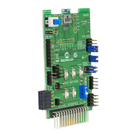
Sensor Board RN4870 PICtail/PICtail PLUS DAUGHTER BOARD Figure 2-1 shows the interfaces of the RN4870 PICtail/PICtail Plus Daughter board. The PICtail board can be used in Standalone mode powered from either an external ® USB host, coin-cell battery, or from the PIC Explorer Development board. - Page 16 Configuration mode to update firmware or configuration settings 22. Ground Test Connector (J2) CN1, CN2 and CN3 are header pins to the RN4870 module pins. The headers are used either to connect the Sensor board to the PICtail board or as test points.
-
Page 17: Rn4871 Pictail/Pictail Plus Daughter Board
The RN4871 PICtail uses the RN4871 BLE module as shown in Figure 2-2. Due to its smaller footprint, the RN4871 has less IO pins than the full size RN4870 module. For ® the specific pinouts of the RN4870 and the RN4871 modules, refer to the “ Bluetooth 4.2 Low Energy Module Data Sheet”... -
Page 18: Sensor Board
The Sensor board is an accessory designed for the RN4870 PICtail/PICtail Plus Daughter board to demonstrate digital and analog IO capabilities over Bluetooth Low Energy connections. In order to use the Sensor board with the RN4870, it must be con- figured as described in Chapter 4. -
Page 19: Chapter 3. Quick Start Guide
Chapter 3. Quick Start Guide OVERVIEW The simplest method to access the RN4870/71 is to connect it to a PC host that supports USB CDC virtual COM (serial) ports. Simple ASCII commands can be sent to the RN4870/71 module by using a terminal emulator application. - Page 20 COM PORT SETTINGS FOR TERMINAL EMULATOR 4. Enter Command mode by sending the command escape sequence $$$. Press- ing the dollar sign ($) three times puts the RN4870/71 into Command mode and CMD> prompt is displayed. When interacting directly with the RN4870/71 using terminal emulator, enable local echo feature on the RN4870/71.
-
Page 21: Changing Settings Using Ascii Commands
RESULTS OF “D” TO DISPLAY BASIC CONFIGURATION CHANGING SETTINGS USING ASCII COMMANDS The RN4870/71 PICtail is shipped with a default configuration not including GATT ser- vices as noted by the result of the previous command D (display basic configuration). The services value is set to Services=00. The RN4870 module can be discovered ®... -
Page 22: Connecting To The Rn4870/71 Using Smartdiscover App
RN4870/71 PICtail™/PICtail Plus Daughter Board User’s Guide 3. After any Set commands issued, the RN4870/71 module needs a device reboot (R,1) for the changes to take effect. To verify the configuration settings, perform the following steps: a) Type $$$ to enter Command mode... - Page 23 SmartDiscover App on an iOS device. FIGURE 3-7: SMART DISCOVER (iOS) 4. Verify that the RN4870/71 device name, BLE-b1b0, is displayed. In this exam- ple, the device name is BLE-C071 as shown in Figure 3-7.
-
Page 24: Creating Custom Gatt Services
The cut and paste method saves time and minimizes keyboard entry errors. The configuration text files are included in the RN4870 Sensor board Support package that can be downloaded from the product web page at www.microchip.com/RN4870. -
Page 25: Accessing Gatt Service Using Uart Commands And Smartdiscover App
1. To write a value to the GATT Server characteristic C501, use the Server Handle Write (SHW) and the Server Handle Read (SHR) commands with reference 0072 as first parameter, following by hex-byte values as shown in Figure 3-11. 2016 Microchip Technology Inc. DS50002547A-page 25... - Page 26 GATT characteristic C501. In steps 1 and 2, tap on the name of your device (BLE-C071 >), on the UUID (BF3FBD80063F11E59E690002A5D5C501 and on Read in step 3. The charac- teristic value is read from the RN4870/71 into the Smart Discover App. FIGURE 3-12: USING SMARTDISCOVER TO READ GATT CHARACTERISTIC VALUE ...
-
Page 27: Reading Sensor Board Peripheral Io Ports Using Uart Commands
• Type $$$ to enter Command mode • Enter SF,1 and verify that the module reboots after the command is entered. 3. Type the following sequence of commands to set the RN4870 IO pin into the con- figuration as illustrated in Figure 3-13: •... - Page 28 RN4870/71 PICtail™/PICtail Plus Daughter Board User’s Guide FIGURE 3-13: RN4870 PINS USED BY SENSOR BOARD INTERFACE 4. After the IO ports are configured and the module is rebooted, perform the com- mands shown in Figure 3-14 to read and write peripheral IO.
-
Page 29: Chapter 4. Rn4870 Sensor Board
OVERVIEW The RN4870 must be configured to enable the Sensor Board peripherals, and to enable the BLESensor App to communicate with the RN4870. The following is the con- figuration procedure: 1. Configure Peripheral IO port to sensors using command SW. -
Page 30: Sensor Board Gatt Service
RN4870 MODULE SETTINGS CONFIGURATION SENSOR BOARD GATT SERVICE The data from the RN4870 peripheral IO are stored in the characteristics of a custom GATT service accessed by the Sensor Board BLE Client App. To create the Sensor Board GATT Service, enter the following commands while in Command mode: 1. - Page 31 SENSOR BOARD GATT SERVICE DECLARED IN RN4870 Figure 4-2 illustrates that a custom GATT service has been created in the RN4870 module. A 16-bit handle is assigned to each characteristic where each characteristic has a value in the handle and a property handle. The characteristic value and the prop- erties are accessed by a short and more efficient 16-bit handle instead of the 128-bit UUID value.
-
Page 32: Transferring Sensor Data Into Gatt Service Using Scripting
Press OK to load the script into the RN4870. e) After the script is pasted into the RN4870, exit Script Entry mode by pressing the <ESC> key. An AOK response is sent to the terminal. The script entry is... - Page 33 FIGURE 4-4: COMPLETED SENSOR BOARD SCRIPT Enter command R,1 to reboot the RN4870 module. After the reboot, the Sensor board is ready to use. The script event handlers can be seen on the TeraTerm display as shown in Figure 4-5.
-
Page 34: Blesensorapp Smartphone App
RN4870/71 PICtail™/PICtail Plus Daughter Board User’s Guide BLESENSORAPP SMARTPHONE APP The RN4870 Sensor board is a BLE Peripheral that advertises a GATT service to BLE Central devices. In this demonstration, the BLE Central device is a smartphone appli- cation named BLESensorApp. It is available for iOS and Android platforms via iTunes AppSTORE, and Google Play Store, respectively. - Page 35 In the Sensor board demo, slider control is used on the App to select a blink rate value. The value is written to the GATT characteristic in the RN4870. The sensor script monitors the Characteristic for incoming data then extracts the value which is subse- quently written to the Pulse-With Modulation (PWM) output peripheral to control LED blink rate.
-
Page 36: Provision Utility
(SW7 must in be in position 1: Application mode) 3. Connect the RN4870 to the host PC using the micro USB cable and verify that LED1 blinks blue with long interval. 4. Wait for the RN4870 board to successfully enumerate as a Serial Port device. - Page 37 7. Ensure that the RN4870 board is still connected to the Windows PC and suc- cessfully enumerated. Click Scan button to scan for all the UART COM ports available on the Windows PC. Note: Ensure that the COM port on which the RN4870 board is enumerated is not opened by another application like a Serial Terminal application.
- Page 38 RN4870/71 PICtail™/PICtail Plus Daughter Board User’s Guide FIGURE 4-11: CONFIGURATION UTILITY: CONFIGURING MODULE 10. After the provisioning process is completed, an information dialog window pops up to inform about the successful provisioning of the RN4870 module. Refer to Figure 4-12. Note: After the provisioning is successful, the RN4870 automatically reboots and retains the provisioned configuration.
-
Page 39: Chapter 5. Pic Configuration Library
The RN4870/71 module uses the UART interface for configuration and data transfer. The RN4870/71 Configuration and Events are defined as Command and Response protocol packets. A Command packet is sent to the RN4870/71 over UART to update a parameter. A Response packet is received from the RN4870/71 over UART for the command issued. - Page 40 RN4870/71 PICtail™/PICtail Plus Daughter Board User’s Guide 3. Optionally, a debug UART port can be connected to a PC terminal emulator program. Note: On the Explorer 16 Development board, the debug UART is available on the DB9 UART serial connector P1. On the PIC18 Explorer board, the debug UART needs to be manually tapped from pins RG1/TX2 and RG2/RX2 on the J5 header using external wiring.
- Page 41 “ Bluetooth Low Energy Module User’s Guide” (DS50002466). 7. Once connected, the data can be transmitted from the RN4870/71 through the debug UART port to the BtChat app over Bluetooth link. 8. Enable Show Rx Text option in the BtChat app setting. The BtChat app can resend data to the RN4870/71 that is later received through the debug UART.
- Page 42 RN4870/71 PICtail™/PICtail Plus Daughter Board User’s Guide NOTES: 2016 Microchip Technology Inc. DS50002547A-page 42...
-
Page 43: Appendix A. Updating Pictail Firmware
Appendix A. Updating PICtail Firmware OVERVIEW Firmware for the RN4870/71 PICtail can be updated using a PC Tool isupdate.exe over the USB port. The latest RN4870/71 firmware images and the isupdate.exe tool are available from the product web page at www.microchip.com/RN4870. - Page 44 RN4870/71 PICtail™/PICtail Plus Daughter Board User’s Guide 6. Click the Connect button and verify the “Port connect -> COMxx” is displayed in the text box. 7. Verify firmware update is successfully completed. The “End of Write Memory” message is displayed.
-
Page 45: Appendix B. Schematics And Bom
This appendix provides the schematics and the Bill of Materials (BOM) for the RN487x PICtail™/PICtail Plus Daughter board: • RN4870 PICtail Schematic • RN4870 PICtail BOM • RN4871 PICtail Schematic • RN4871 PICtail BOM • RN4870 Sensor Board Schematic • RN4870 Sensor Board BOM 2016 Microchip Technology Inc. DS50002547A-page 45... -
Page 46: Rn4870 Pictail Schematic
RN4870 PICtail SCHEMATIC Figure B-1 shows the schematic for the RN4870 PICtail™/PICtail Plus Daughter board. FIGURE B-1: RN4870 PICtail SCHEMATIC VBAT Coin Cell USB_5V RN4870 MODULE USB_3V3 USB_3V3 USB to UART Converter 300R PIC_3V3 PIC_3V3 Configuration MODE Power Source Option 2.2k... -
Page 47: Rn4870 Pictail Bom
ERJ-3GEYJ472V SMD 0603 R10, R11, R13 RES TKF 2.2k 1% 1/10W Panasonic ERJ-2RKF2201X SMD 0402 RES TKF 10k 5% 1/8W SMD Panasonic ERJ-6GEYJ103V 0805 RES TKF 470R 5% 1/8W Panasonic ERJ-6GEYJ471V SMD 0805 2016 Microchip Technology Inc. DS50002547A-page 47... - Page 48 RN4870/71 PICtail™/PICtail Plus Daughter Board User’s Guide TABLE B-1: RN4870 PICtail BOM Reference Description Manufacturer Manufacturer Part Number RES TKF 1k 5% 1/8W SMD Panasonic ERJ-6GEYJ102V 0805 RES TKF 4.7K 1% 1/16W KOA Speer RK73H1ETTP4701F 0402 BATT HOLDER COIN 1 TH...
-
Page 49: Rn4871 Pictail Schematic
RN4871 PICtail SCHEMATIC Figure B-2 shows the schematic for the RN4871 PICtail™/PICtail Plus Daughter board. FIGURE B-2: RN4871 PICtail SCHEMATIC USB to UART Configuration USB_5V 300R Power Source Option MODE 47uF Test Mode 4.7k Micro USB DIP 1 SPST TANT-C APP Mode 0603 0805... -
Page 50: Rn4871 Pictail Bom
RN4870/71 PICtail™/PICtail Plus Daughter Board User’s Guide RN4871 PICtail BOM TABLE B-2: RN4871 PICTAIL BOM Reference Description Manufacturer Manufacturer Part Number C8, C10 CAP CER 4.7 µF 10V 10% KEMET C0603C475K8PACTU X5R SMD 0603 CAP TANT 47 µF 16V 10%... - Page 51 MCHP RF BLUETOOTH Microchip Technology Inc. RN4871-V/RM118 RN4871 Microchip Bluetooth module U2, U11 MCHP ANALOG LDO 3.3V Microchip Technology Inc. MCP1700T-3302E/TT MCP1700T-3302E/TT SOT-23-3 MCHP INTERFACE USB Microchip Technology Inc. MCP2200-I/SS-ND UART MCP2200-I/SS SSOP-20 2016 Microchip Technology Inc. DS50002547A-page 51...
-
Page 52: Rn4870 Sensor Board Schematic
RN4870/71 PICtail™/PICtail Plus Daughter Board User’s Guide RN4870 SENSOR BOARD SCHEMATIC Figure B-3 shows the schematic for the RN4870 Sensor board. FIGURE B-3: RN4870 SENSOR BOARD SCHEMATIC TP LOOP Black TP LOOP Black PDV_P8104 100R 0603 PTS645SM43SMTR92 LFS 0.010uF 0.010uF... -
Page 53: Appendix C. Bluetooth Low Energy Primer
GATT client to GATT server Read 0x02 Read value of characteristic. Value is sent from GATT server to GATT client Broadcast 0x01 Broadcast value of characteristic Note 1: These features are supported in future firmware releases 2016 Microchip Technology Inc. DS50002547A-page 53... - Page 54 GATT client using Write, Read, Indication and Notifications. Write-REQ enables the GATT client to update characteristic values on the Peripheral's GATT server. The write requests can be performed using RN4870 CHW and CUW com- mands. Refer to Section 3.6 “Accessing GATT Service Using UART Commands and SmartDiscover App”...
-
Page 55: Appendix D. Sensor Board Configuration Command Text
This appendix provides an example for configuration commands to use all the sensors in the Sensor board in a GATT service. • RN4870 Module Settings • RN4870 Sensor Board GATT Service • Sensor Board Script D.1.1 RN4870 Module Settings S-,RN4870... - Page 56 RN4870/71 PICtail™/PICtail Plus Daughter Board User’s Guide D.1.3 Sensor Board Script To configure the Sensor board, enter the following sequence of commands: @PW_ON IA,Z SM,2,0000 SM,1,0002 %0078=?FUNC1 ?FUNC1 [,1,1,$PM1,$PM2 @DISCON SM,1,0000 SM,2,0000 SM,3,0000 @CONN SM,1,0000 SM,2,0000 SM,3,001A @TMR1 IA,Z IA,FF,CD00FE14AD11CF40063F11E5BE3E0002A5D5C51B000C000D...
-
Page 57: Worldwide Sales And Service
Thailand - Bangkok Tel: 408-735-9110 Sweden - Stockholm Tel: 86-29-8833-7252 Tel: 66-2-694-1351 Tel: 408-436-4270 Tel: 46-8-5090-4654 Fax: 86-29-8833-7256 Fax: 66-2-694-1350 Canada - Toronto UK - Wokingham Tel: 905-695-1980 Tel: 44-118-921-5800 Fax: 905-695-2078 Fax: 44-118-921-5820 2016 Microchip Technology Inc. DS50002547A-page 57 11/07/16... - Page 58 Mouser Electronics Authorized Distributor Click to View Pricing, Inventory, Delivery & Lifecycle Information: Microchip RN-4870-SNSR RN-4871-PICTAIL...
Need help?
Do you have a question about the RN4870 and is the answer not in the manual?
Questions and answers