
Related Manuals for Aalborg Command Module


Summary of Contents for Aalborg Command Module
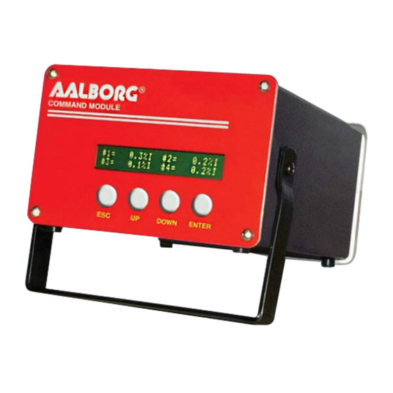
- Page 1 Technical Data Sheet No. TD9704M Rev F Date of Issue: August 2010 OPERATING MANUAL SDPROC COMMAND MODULES...
- Page 2 Aalborg is a registered trademark of Aalborg Instruments & Controls. NOTE: Aalborg reserves the right to change designs and dimensions at its sole discretion at any time without notice. For certified dimensions please contact Aalborg...
-
Page 3: Table Of Contents
TABLE OF CONTENTS UNPACKING THE SDPROC COMMAND MODULE........Inspect Package for External Damage............Unpack the Command Module..............Returning Merchandise for Repair............... INSTALLATION..................... Location of Installation................Electrical Connections................. b.2.1 Connecting Flow Transducers..............b.2.2 Power Input....................b.2.3 Applying Power to the SDPROC.............. - Page 4 e.2.9 Program Settings Display................e.2.9.1 Batch Program Settings Display..............e.2.9.2 Timer Program Settings Display..............e.2.10 Status Check....................Multi Channel SDPROC................... e.3.1 Start up Display.................... e.3.2 Main Display....................e.3.3 Channel Select....................e.3.4 Set Point Display.................... e.3.5 Control Mode Display..................e.3.6 Totalizer/Alarm Status Display............... e.3.7 Setup Channel Display..................
- Page 5 NETWORK COMMUNICATION INTERFACE (OPTIONAL)......0Base-T RJ-45 Pinout................Network Protocols..................i.2.1 DHCP......................i.2.2 DNS......................i.2.3 IP Address....................Configuration....................Operation Using the SDPROC Web Page............Operation Using the SDPROC Telnet Console..........TROUBLESHOOTING..................Common Conditions..................Troubleshooting Guide..................Technical Assistance..................APPENDIX 1 COMPONENT DIAGRAM..............APPENDIX 2 DIMENSIONAL DRAWINGS............
-
Page 7: (A) Unpacking The Sdproc Command Module
(a) UNPACKING THE SDPROC COMMAND MODULE a.1 Inspect Package for External Damage Your SDPROC Command Module was carefully packed in a sturdy cardboard carton, with anti static cushioning materials to withstand shipping shock. Upon receipt, inspect the package for possible external damage. In case of external damage to the package contact the shipping company immediately. -
Page 8: Electrical Connections
b.2 Electrical Connections b.2.1 Connecting Flow Transducers Attach the 15 pin “D” connector cable(s) between the interface panel on the rear of the SDPROC and the Flow Meter/Controller transducer(s). (Number of channels will vary from one to four in accordance with configuration and options purchased.) Figure b-1, Interface Panel for SDPROC. -
Page 9: Power Input
Use of the SDPROC in a manner other than that specified in this manual or in writing from Aalborg7, may impair the protection provided by the equipment. Figure b-2, Pin out chart for CHANNEL l/2/3/4 “Flow Transducers” connector. b.2.2 Power Input Make sure the POWER switch on the back of the SDPROC is OFF. -
Page 10: Relays Interface
RS-232 serial communication interface is standard for all models and sup- ported via a 9 pin “D”-connector at the back panel of the Command Module. RS-232 Software interface commands set allows communications with the unit using either a custom software program or a “dumb terminal”... -
Page 11: Ce Compliance
RELAYS PORT CABLE: Optional shielded cable with female 25 pin “D” connector to connect to command module relays port. DATA PORT CABLE: Optional shielded cable with male 25 pin “D” connector to con- nect to command module data port. [Cable length may not exceed 9.5 feet (3 meters)]. d.1 CE Compliance Any SDPROC are in compliance with the below stated test standards currently accepted. -
Page 12: (E) Operating Instructions
(e) OPERATING INSTRUCTIONS There are four buttons on the front panel of the SDPROC from which all functions can be controlled or set. These are labeled “ESC”, “UP”, “DOWN”, and “ENTER”. Figure e-1, Control Panel for SDPROC. e.1 Preparation and Warm Up It is assumed that the SDPROC and the Mass Flow Meter(s) and/or Controller(s) have been correctly installed as described in this and the AFM/AFC/DFC/GFM/GFC manuals. -
Page 13: Control Mode Status
The Main Display will indicate the following info: = “F” current flow rate in % F.S. (NOTE: An “I” is indicated on the display immediately following the displayed flow when the SDPROC is set for internal reference and “E” for external reference.) = “S”... -
Page 14: Totalizer/Alarm Display
Set Point Display for 1 channel SDPROC The UP button under the “+” and DOWN button under the “-” will increase and decrease the set point respectively. Once set, press the ENTER button under EXIT on the display to return to the Main Display. This set point is only applicable when the SDPROC is used in INTERNAL REFERENCE mode. -
Page 15: Internal/External/Program Reference
Setup Channel screen allows to configure: = General device settings: Int./Ext. Reference, Gas density, Engineering Units, Full Scale Flow in L/Min and Relays assignment. = Alarm Properties: Mode, High and Low settings in % F.S., Delay Time, Action. = Totalizer Properties: Mode, Start Flow, Stop Volume, Action. = Program Properties: Batch parameters and Timer Settings. -
Page 16: Setup Engineering Units Display
e.2.6.3 Setup Engineering Units Display Press the UP or DN button, to change current engineering units. The following engi- neering units are supported: %F.S., SLPM, SLPH, SCCM, SCCH, SCFM, SCFH, SCMM, SCMH, LBPM, LBPH, GRPM, GRPH. If no more settings are required, press the ENTER button under EXIT on the display, to go back to the Main Display. -
Page 17: Setup Alarm Display
The following display will appear. Press ESC button under NEXT on the display or the ENTER button under EXIT on the dis- play, to go back to the Main Display. e.2.7 Setup Alarm Display Before enabling the Alarm make sure all alarm settings are configured properly. High and Low alarm values have to be entered in %F.S. -
Page 18: Setup Alarm Delay Display
e.2.7.4 Setup Alarm Delay Display Alarm Delay specifies the time interval in seconds the Alarm conditions have to be True (without any interruption) before Alarm will be activated. If zero value is set, the Alarm will be activated immediately after Alarm conditions are met. Pressing (+) or (-) will increment or decrement Alarm Delay settings per 1 second respectively. -
Page 19: Setup Totalizer Mode Display
e.2.8.1 Setup Totalizer Mode Display To change Totalizer Mode in ENABLED or DISABLED, press the button (UP, DOWN respectively) directly below the mode shown on the display. To return to the Main Display, press the ENTER button under EXIT on the display. Press the ESC button under NEXT on the display to go to the Totalizer Start settings. -
Page 20: Program Settings Display
To change Totalizer Action in NONE, BUZZER or VALVE, press the button (ESC, UP, DOWN respectively) directly below the text shown on the display. If Buzzer action is chosen, the audible signal will be activated when Totalizer conditions become true. In order to deactivate the audible signal during operation press any button on the key pad (NOTE: The Totalizer has to be reset to zero or disabled). - Page 21 The same is true for 0 seconds, pressing the (-) button will rollover time settings to 99999 seconds. Press the ENTER button under MULT on the display, to change the value of the multiplier to 10. Continuing to press the ENTER button under MULT on the display, will change the value of the multiplier first to 100 and then back to 1.
-
Page 22: Timer Program Settings Display
e.2.9.2 Timer Program Settings Display The Timer Flow Control allows execution of a custom, user preset program of up to 96 steps. Each step can be pre-programmed for a particular date, time, and set point value in % F.S.. Every step has two fields: starting date, time and set point in % F.S. Before executing, the program should be entered in the program table in the format: TIME/DATE [XX.XX XX/XX/XXXX] - SETPOINT [% F.S.]. -
Page 23: Status Check
e.2.10 Status Check While in the Main Display press the UP button on the front panel of the SDPROC. The Relays Assignment Status will appear. Relays Status Display One channel SDPROC Pressing the UP button again will bring up the Totalizer Settings screen. Pressing the DOWN button will return to the Main Display. -
Page 24: Main Display
e.3.2 Main Display After a few seconds, the Start up display will clear, and the Main Display will appear. Main Display for 2 channel SDPROC Main Display for 3 channel SDPROC Main Display for 4 channel SDPROC Readings are linear 0 to 100% of full scale. Direct engineering units are available on another screen. -
Page 25: Set Point Display
nel 3 has been selected.) The following Set Point Display will appear. e.3.4 Set Point Display Set point Display Multi channel SDPROC The screen above assumes that the full scale flow rate for channel #3 is set to 5.0 SLPM and current units of measure is SLPM. The UP button under the “+” and DOWN button under the “-”... -
Page 26: Setup Channel Display
e.3.7 Setup Channel Display Pressing the Down button under Main Display screen (see section e.3.2) will display SETUP CHANNEL screen shown below. Setup Channel Display for Multi channel SDPROC Press the button on the SDPROC panel under the appropriate channel number displayed. This will select that channel for device settings configuration. -
Page 27: Setup Gas Density Display
e.3.7.2 Setup Gas Density Display The proper settings of the gas density (in grams per liter) are required for mass based engineering units (LBPH, LBPM, GrPH, GrPM). Press the ENTER button under (--->) on the display, to move the flashing cursor to the desired position. Pressing (+) or (-) will increment or decrement a particular digit respectively. -
Page 28: Setup Relays Assignment Display
change the decimal point to any desired digit, next move the cursor to the required position, and adjust it to the decimal point with the (+) or (-) button. When complete with Full Scale Flow Rate settings, press the ESC button under NEXT on the display, to go to the Relays Assignment screen. -
Page 29: Setup Alarm Low Display
NEXT on the display to go to the Alarm Low settings. The following Setup Alarm Low Display will appear. e.3.8.2 Setup Alarm Low Display Pressing (+) or (-) will increment or decrement Low Alarm settings per 0.1% F.S. respectively. If no settings are required for High Alarm press the ENTER button under EXIT on the display, to go back to the Main Display. -
Page 30: Setup Totalizer Display
In order to deactivate the audible signal during operation, press any button on the key pad (NOTE: Alarm Conditions have to be removed or Alarm for the corresponding channel has to be disabled). If Valve action is chosen the power to the mass flow controller valve will be shut off, allowing the valve to mechanically close. -
Page 31: Setup Totalizer Stop Volume Display
under NEXT on the display to go to the Totalizer Stop settings. The following Setup Totalizer Stop Volume Display will appear. e.3.9.3 Setup Totalizer Stop Volume Display The proper setting of the Totalizer Stop Volume (in volume/mass based engineering units) is required if the Totalizer is set to Enabled. The engineering unit for Totalizer Stop Volume has to be related to the current active engineering unit. -
Page 32: Batch Program Settings Display
There are three program options for multi channel SDPROC: BATCH, TIMER and RATIO flow control. e.3.10.1 Batch Program Settings Display Batch Flow Control allows execution of a custom, user preset program of up to sixteen steps. During execution of the program the user can activate or deactivate the LOOP mode. -
Page 33: Timer Program Settings Display
BATCH mode control screen with batch disabled The two digit number after “SE:” indicates the number of the enabled steps for execu- tions. Press the UP button under STEPS on the display, to change the number of steps from the batch program to be executed. With 16 steps enabled on the screen, press- ing the Up button one more time will rollover the number of steps back to 1. -
Page 34: Ratio Program Settings Display
Ratio Flow allows controlling flow of the mixture of up to four different gases (for 4 channel Command Module) with preset values of the ratio in % for each channel. The flow rate of the mixture can be incremented or decremented by changing the set point of the master channel #1. - Page 35 By default, Ratio Mode is disabled for each channel. In order to be able to enable Ratio Mode, the value of the ratio in % for a particular channel has to be more than 0%. It is recommended to begin Ratio settings from the master channel #1 (master channel has to be set to the highest value from the mixture).
-
Page 36: All Valves Control
Make sure that the total value of the mixture is equal to 100% in the end of the ratio settings for all required channels. When complete with ratio value settings for all required channels, go to the ratio mode settings screen for each required channel and change the ratio mode from DISABLED to ENABLED. -
Page 37: Real Time Clock Settings
e.3.12 Real-time Clock Settings Real Time Clock Settings Display for SDPROC Normally date and time for the Real-time Clock are set by the factory, unless the bat- tery was replaced, or the CPU core was removed from the main board of the SDPROC. In order to change date and time settings press the ENTER button under SET on the display. -
Page 38: Maintenance
Pressing the UP button again will bring up the Alarm Mode Status for all channels. Alarm Mode Status Display for Multi channel SDPROC Pressing the UP button again will bring up the Totalizer Mode Status for all channels. Totalizer Mode Status Display for Multi channel SDPROC Press UP one more time to return to the Main Display. -
Page 39: Digital To Analog (D/A) Slope Calibration
Calibration Mode Display Proceed with instructions outlined in sections g.1 and g.2. g.1 Digital to Analog (D/A) Slope Calibration Select the D/A calibration mode from the Calibration Menu. The following display will appear. NOTE: The digital to analog (D/A) slope has to be calibrated for each channel individually! Using an accurate digital multimeter, measure the A/D output DC voltage between pins 9 (positive) and 10 (ground) of the Channel 1 15 pin “D”... -
Page 40: Analog To Digital (A/D) Calibration
The display should show the D/A value between 3900 and 4095. Save the D/A slope parameter by pressing the CAL (ENTER button).Proceed with D/A calibration for as many channels as required. When digital to analog (D/A) slope is calibrated for last available channel, the following display will appear. -
Page 41: (H) Rs-232 Software Interface Commands
Press any key when done with 5.000 Vdc connections. The following display will appear. The display should show the A/D offset values between 3850 and 4095. If any value is outside of those limits, the PC board is defective. Save the A/D offset parameters by pressing the CAL (ENTER button). - Page 42 The protocol described below allows for communications with the unit using either a custom software program or a “dumb terminal.” All values are sent as printable ASCII characters. The command parameters are delimited by a space character and the com- mand string is always terminated with a carriage return character, (line feeds are auto- matically stripped out by the SDPROC).
-
Page 43: Ascii Commands
h.3 ASCII Commands No Type Description Command Argument 1 Argument 2 Argument 3 Argument 4 Return string Set Full Scale Flow CHANNEL VALUE FF CHANNEL in SLPM 1 char. [1-4] float VALUE K[CR][LF] [0-99999.0] Ex: FF 4 10.0 [CR][LF] Set current CHANNEL INDEX EU CHANNEL... - Page 44 No Type Description Command Argument 1 Argument 2 Argument 3 Argument 4 Return string Single Data String with current Request Returns reading in %F.S a string for all channels. containing readings If channel not in %F.S. for all calibrated [*] available channels.
- Page 45 No Type Description Command Argument 1 Argument 2 Argument 3 Argument 4 Return string Set ALARM HIGH CHANNEL VALUE AH CH VALUE flow margin 1 char. float OK[CR][LF] in %F.S. [1-4] [0-105.0] Ex: AH 2 5.0 OK[CR][LF] Read ALARM AS ST ST[CR] STATUS Returns: [LF] Ex: AS 0 0 - NO ALARM...
- Page 46 Command Argument 1 Argument 2 Argument 3 Argument 4 Return string No Type Description General status SCF MODEL T command #1 XXX.X XXX.X Returns: Instrument U U OK[CR][LF] model, TCP/IP flag, Ex: SCF SDPROC2 Full scale flow in 0 5.000 1.000 SLPM, Current E.U 1 1 OK[CR][LF] For all...
- Page 47 Host Name** Name (max. 25 Host OK[CR][LF] (max. 25 characters) characters) Read current Domain Name: settings for aalborg.com[CR] Domain Name and [LF] Host Name: Host Name** sdproc[CR][LF] Set the DHCP flag MODE DHP MODE (will take affect on char...
-
Page 48: Network Communication Interface (Optional)
(i) Network Communication Interface (optional) i.1 10Base-T RJ-45 Pinout The optional 10Base-T Ethernet network (RJ-45) system is used in the SDPROC for network connectivity. The 10 Mbps twisted-pair Ethernet system operates over two pairs of wires. One pair is used for receiving data and the other pair is used for trans- mitting data. -
Page 49: Dns
i.2.2 DNS DNS, Domain Name System enables individual computers and devices to be recog- nized over the network base on specific name instead of an IP address. For example, instead of having to use http://192.168.1.19 (which is device IP address), we can use only http://sdproc or any eight characters name stored as the Host Name in the SDPROC. -
Page 50: Operation Using The Sdproc Web Page
Figure i-2 Pinging SDPROC MS-DOS Prompt i.4 Operation Using the SDPROC Web Page Start your Web browser. From the browser type http://192.168.1.19 (if IP address was changed use new IP address). The Home Page, shown below, will be displayed. Figure i-3 Network Password Page Enter User Name and Password and click OK. -
Page 51: Operation Using The Sdproc Telnet Console
Once you are done with the user Name and Password, the Home Page, shown below, will be displayed. Figure i-4 Using SDPROC with Telnet Console Figure i.4 SDPROC control Page You can type the number of the channel you want to monitor or control. You can also enter the desired value of the set point. -
Page 52: Troubleshooting
(J) TROUBLESHOOTING J.1 Common Conditions Your SDPROC Command Module was thoroughly checked at numerous quality control points during and after manufacturing and assembly operations. It was calibrated in accordance to your desired conditions and options. It was carefully packed to prevent damage during shipment. Should you feel that the... -
Page 53: Troubleshooting Guide
Aalborg7 Instruments will provide technical assistance over the phone or e-mail to qualified repair personnel. Please call our Technical Assistance at 845-770-3051. Please have your Serial Number and Model Number ready when you call. The e-mail address for technical assistance is: support@ aalborg.com. -
Page 54: Appendix 1 Component Diagram
APPENDIX 1 COMPONENTS DIAGRAM SDPROC MAIN PC BOARD... -
Page 55: Dimensional Drawings
APPENDIX 2 DIMENSIONAL DRAWING SDPROC COMMAND MODULE... -
Page 56: Appendix 3 Warranty
Aalborg7 and the provisions of this warranty. Defective products will be repaired or replaced solely at the discretion of Aalborg at no charge. Shipping charges are borne by the customer. This warranty is void if the equipment is damaged by accident or misuse, or has been repaired or modified by anyone other than Aalborg or factory authorized service facility.
Need help?
Do you have a question about the Command Module and is the answer not in the manual?
Questions and answers