Table of Contents
Advertisement
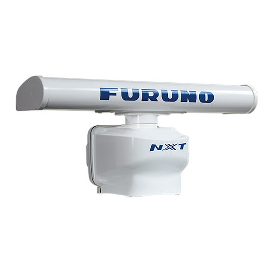
Installation Manual
RADAR SENSOR
DRS6A-NXT
MODEL
(Product Name: SOLID STATE DOPPLER RADAR)
SAFETY INSTRUCTIONS ................................................................................................ i
SYSTEM CONFIGURATION .......................................................................................... iii
INSTALLATION SPECIFICATIONS............................................................................... iv
FOREWORD .................................................................................................................... v
EQUIPMENT LISTS........................................................................................................ vi
1. INSTALLATION AND WIRING................................................................................... 1
1.1 Mounting Considerations ......................................................................................................1
1.2 Included Items.......................................................................................................................4
1.3 Required Tools and Materials ...............................................................................................5
1.4 Fastening the Radiator to the Radiator Bracket....................................................................6
1.5 Mounting the Antenna Unit ...................................................................................................8
1.6 Wiring..................................................................................................................................11
2. INITIAL SETUP......................................................................................................... 15
2.1 Initial Setup for TZT9/TZT14/TZTBB ..................................................................................16
2.2 Initial Setup for TZTL12F/TZTL15F ....................................................................................18
3. MAINTENANCE, TROUBLE SHOOTING ................................................................ 21
3.1 Maintenance .......................................................................................................................22
3.2 Troubleshooting ..................................................................................................................23
3.3 Replacement of Fuse..........................................................................................................23
3.4 Life of Parts.........................................................................................................................24
APPENDIX 1 RADIO REGULATORY INFORMATION ............................................AP-1
SPECIFICATIONS ..................................................................................................... SP-1
PACKING LIST ............................................................................................................ A-1
OUTLINE DRAWING ................................................................................................... D-1
INTERCONNECTION DIAGRAM ................................................................................ S-1
www.furuno.com
All brand and product names are trademarks, registered trademarks or service marks of their respective holders.
Advertisement
Table of Contents
Troubleshooting

Related Manuals for Furuno DRS6A-NXT


Summary of Contents for Furuno DRS6A-NXT
-
Page 1: Table Of Contents
Installation Manual RADAR SENSOR DRS6A-NXT MODEL (Product Name: SOLID STATE DOPPLER RADAR) SAFETY INSTRUCTIONS ....................i SYSTEM CONFIGURATION ..................iii INSTALLATION SPECIFICATIONS................iv FOREWORD ........................v EQUIPMENT LISTS......................vi 1. INSTALLATION AND WIRING................... 1 1.1 Mounting Considerations ......................1 1.2 Included Items........................4 1.3 Required Tools and Materials ....................5... -
Page 2: Safety Instructions
SAFETY INSTRUCTIONS The installer of the equipment must read the safety instructions before attempting to install the equipment. Indicates a potentially hazardous situation which, WARNING if not avoided, can result in death or serious injury. Indicates a potentially hazardous situation which, CAUTION if not avoided, can result in minor or moderate injury. - Page 3 - Name: FURUNO EUROPE B.V. - Address: Ridderhaven 19B, 2984 BT Ridderkerk, The Netherlands Program No. • 0359423-01.** ** denotes minor modifications. CE declarations With regard to CE declarations, please refer to our website (www.furuno.com), for further information about RoHS conformity declarations.
-
Page 4: System Configuration
Multi Function Display NavNet TZtouch/Navnet TZtouch 2 NavNet TZtouch/Navnet TZtouch 2 This radar series is compatible with the FURUNO Multi Function Displays and software version combinations shown below. The combination with other models or software versions may not op- erate properly. -
Page 5: Installation Specifications
INSTALLATION SPECIFICATIONS Voltage of Ship’s Main and Usable Radiator Radiator Supply Voltage XN10A XN12A XN13A 12 VDC Not available 24 VDC Voltage of Ship’s Main and Usable Cable Length Cable Length Supply Voltage 10 m 15 m 20 m 30 m 12 VDC Not available Not available... -
Page 6: Foreword
FOREWORD A Word to the Owner of the DRS6A-NXT Marine Radar Congratulations on your choice of the FURUNO DRS6A-NXT Marine Radar. We are confident you will see why the FURUNO name has become synonymous with quality and reliability. Since 1948, FURUNO Electric Company has enjoyed an enviable reputation for innovative and dependable marine electronics equipment. -
Page 7: Equipment Lists
EQUIPMENT LISTS Standard supply Name Type Code No. Remarks Scanner Unit RSB-137-119 Radiator XN10A 3.4 ft XN12A 4 ft XN13A 6 ft Installation CP03-37101 001-426-290 For scanner unit Materials CP03-22901 008-523-690 For radiator CP03-37700 000-033-452 Cable assembly (10 m) CP03-37710 000-033-453 Cable assembly (15 m) CP03-37720... -
Page 8: Installation And Wiring
INSTALLATION AND WIRING NOTICE Do not apply paint, anti-corrosive sealant or contact spray to coating or plastic parts of the equipment. Those items contain organic solvents that can damage coating and plastic parts, especially plastic connectors. Mounting Considerations Select a mounting location, keeping in mind the following points: •... - Page 9 Not recommended • Setup the antenna unit position on the FURUNO Multi Function Display after install- ing the unit, referring to chapter 2. If the antenna unit position is not setup correctly, the radar echoes on the display may not be aligned with the actual target’s bearing.
- Page 10 Consideration for selecting a location for installation (multiple radars) • In case multiple radars are installed on a ship, DO NOT install the DRS6A-NXT with- in the range of the beam area emitted from other radar(s). Use the illustration below for reference when selecting a suitable location for installation.
-
Page 11: Included Items
1. INSTALLATION AND WIRING Included Items Radiator • Flat washer (M8, 4 pcs) • Spring washer (M8, 4 pcs) • Radiator* (1 pc): 3.4 ft, 4 ft or 6 ft • Hex. bolt (M8×30, 4 pcs) • O-ring (1 pc) •... -
Page 12: Required Tools And Materials
1. INSTALLATION AND WIRING Required Tools and Materials The following tools should be prepared in advance for this installation. Name Remarks For making the mounting holes, drill bit: 15 mm Electrical drill Phillips-head screw driver #3, for securing the cable cover Wrench For M8 (Hex. -
Page 13: Fastening The Radiator To The Radiator Bracket
1. INSTALLATION AND WIRING Fastening the Radiator to the Radiator Bracket 1. Remove the radiator cap from the radiator bracket. Radiator bracket Radiator cap 2. Apply marine sealant to the surface of the radiator bracket as shown in the figure below. - Page 14 1. INSTALLATION AND WIRING 4. Apply marine sealant to the thread holes on the bottom of the radiator (4 loca- tions). Marine sealant Bottom view: Radiator 5. Prepare four bolt assemblies; pass the spring washer (M8) and flat washer (M8) through the each hex bolt (M830) then apply marine sealant.
-
Page 15: Mounting The Antenna Unit
1. INSTALLATION AND WIRING 7. Apply marine sealant to the holes and bolts at the locations indicated with arrows in the figure below. Also apply marine sealant to the junction between the radiator and the radiator bracket. Bolt assembly - side view (detailed) Radiator Apply marine sealant Apply marine sealant... - Page 16 1. INSTALLATION AND WIRING 3. Apply marine sealant to the thread of the stud bolts (M1270, 4 pcs). Note: Apply marine sealant to the part of the bolt threads that are inside the bolt hole (see the figure at step 4). 4.
- Page 17 1. INSTALLATION AND WIRING • Hoist the antenna unit slowly. If the antenna unit is hoisted too quickly, the bracket can be damaged. 6. Place the antenna unit on the mounting platform with the BOW mark on the unit aligned with the ship’s bow. BOW mark BOW mark 7.
-
Page 18: Wiring
• When you replace the DRS4A/6A/12A/25A with the DRS6A-NXT, the existing cable cannot be used. Use only the cable assembly supplied with this radar sensor. - Page 19 1. INSTALLATION AND WIRING 3. Wrap the junction of the connectors with self-vulcanizing tape and vinyl tape (local supply) for waterproofing as follows: 1) Wrap the junction of the connectors 2) Change wrap direction and wrap with one layer of self-vulcanizing one layer of the self-vulcanizing tape.
- Page 20 Cable cover - bottom view 8. Reattach the cable cover. 9. Connect the LAN connector of the cable assembly to a LAN port on the FURUNO Multi Function Display or Ethernet HUB. Note 1: Do not connect the LAN connector to on-board LAN.
- Page 21 1. INSTALLATION AND WIRING Note 2: When LAN cable extension is needed, use the optional LAN cable (MOD- Z072) and joint box (TL-CAT-012). After connection is completed, wrap the con- nector with vinyl tape to waterproof the LAN connector. Joint box 10.
-
Page 22: Initial Setup
• TZT9, TZT14 and TZTBB: Version 5.01 or later TZTL12F and TZTL15F: Version 5.01 or later Turn on the antenna unit and FURUNO Multi Function Display. Initial setup for this an- tenna must be done on the FURUNO Multi Function Display. -
Page 23: Initial Setup For Tzt9/Tzt14/Tztbb
[Ra- dar Source] list, close the list and open it again. The name of the an- RDxxxxxx - DRS6A-NXT tenna unit should appear with a RDxxxxxx - DRS6A-NXT check mark, as in the example to the right. - Page 24 2. INITIAL SETUP Menu item Description [Antenna Length] Selects the length of the antenna. RezBoost function reflects the selection of this menu item. [Antenna Longitudinal Po- Referring to the figure on the right, enter the ra- sition] dar antenna positioning bow-stern (Longitudi- nal) and port-starboard (Lateral) position from [Antenna Lateral Position Origin...
-
Page 25: Initial Setup For Tztl12F/Tztl15F
The name of the antenna unit should appear with a check mark, as in the example below. RDxxxxxx - DRS6A-NXT Display example for DRS6A-NXT 4. Drag the [Radar] menu display the menu item [Radar Initial Setup], then tap [Radar Initial Setup]. - Page 26 2. INITIAL SETUP [Radar] menu - [Radar Initial Setup] Menu item Description [Antenna Rotation] Select the antenna rotation speed. [Antenna Heading Align] See "How to align the antenna heading" on page 19. [Main Bang Suppression] If main bang appears at the screen center, slide the circle icon so that the main bang disappears, while watching the radar echo at the left-hand side of the display.
- Page 27 2. INITIAL SETUP Correct bearing of target Displayed position of target (relative to heading) Target Target Displayed Correct position bearing of of target target (relative to heading) Antenna oriented Picture appears with Antenna oriented Picture appears with to port clockwise deviation. to starboard counterclockwise deviation.
-
Page 28: Maintenance, Trouble Shooting
MAINTENANCE, TROUBLE SHOOTING Periodic checks and maintenance are important for proper operation of any electronic system. This chapter contains maintenance and troubleshooting instructions to be fol- lowed to obtain optimum performance and the longest possible life of the equipment. Before attempting any maintenance or troubleshooting procedure, please review the safety information below and at the front of this manual. -
Page 29: Maintenance
3. MAINTENANCE, TROUBLE SHOOTING Maintenance Regular maintenance is important for good performance. Check the points mentioned below every 3 to 6 months to keep the antenna unit in good working order. Check Action Remedy, remarks point Check points every 3 to 6 months Cable Check that all cables are firmly •... -
Page 30: Troubleshooting
3. MAINTENANCE, TROUBLE SHOOTING Troubleshooting The table below provides simple troubleshooting procedures to restore normal opera- tion. If you cannot restore normal operation, contact your dealer for advice. Problem Remedy The multi function display can- • Check that all cables are tightly fastened. not control the radar. -
Page 31: Life Of Parts
3. MAINTENANCE, TROUBLE SHOOTING Life of Parts Antenna Motor When an antenna motor reaches the end of its life, the antenna’s rotation may stop or abnormal noise sounds from the antenna unit. If such symptom occurs, contact your dealer about replacement of the antenna motor. Name Type Code No. -
Page 32: Appendix 1 Radio Regulatory Information
APPENDIX 1 RADIO REGULATORY INFORMATION USA-Federal Communications Commission (FCC) This device complies with part 15 of the FCC Rules. Operation is subject to the following two conditions: (1) This device may not cause harmful interference, and (2) This device must accept any interference received, including interference that may cause undesired operation. -
Page 33: Specifications
FURUNO DRS6A-NXT SPECIFICATIONS OF RADAR SENSOR DRS6A-NXT ANTENNA UNIT Antenna type Slotted waveguide array Antenna length 3.4 ft (XN10A), 4 ft (XN12A), 6 ft (XN13A) Horizontal beam width 2.3° (XN10A), 1.9° (XN12A),1.4° (XN13A) Vertical beam width 22° Gain 27.5 dBi (XN10A), 28.5 dBi (XN12A), 30 dBi (XN13A) - Page 34 FURUNO DRS6A-NXT INTERFACE LAN: 1 port, Ethernet, 100Base-TX POWER SUPPLY 12/24 VDC: 9.5/5.0 A max. ENVIRONMENTAL CONDITIONS Ambient temperature -25°C to +55°C (storage: -30°C to +70°C) Relative humidity 95% or less at +40°C Degree of protection IP56 Vibration IEC 60945 Ed.4 UNIT COLOR N9.5...
- Page 38 Цялостният текст на ЕС декларацията за съответствие може да се намери на следния интернет адрес: Spanish Por la presente, Furuno Electric Co., Ltd. declara que el tipo de equipo radioeléctrico arriba mencionado es conforme con la Directiva 2014/53/UE. (ES) El texto completo de la declaración UE de conformidad está disponible en la dirección Internet siguiente:...
- Page 39 O texto integral da declaração de conformidade está disponível no seguinte endereço de Internet: Romanian Prin prezenta, Furuno Electric Co., Ltd. declară că menționat mai sus tipul de echipamente radio este în conformitate cu Directiva 2014/53/UE. (RO) Textul integral al declarației UE de conformitate este disponibil la următoarea adresă...
- Page 40 ・FURUNO Authorized Distributor/Dealer 9-52 Ashihara-cho, Nishinomiya, 662-8580, JAPAN A : APR 2017 Printed in Japan All rights reserved. A1 : MAY 22, 2017 Pub. No. IME-36680-A1 ( TASU ) DRS6A-NXT 0 0 0 1 9 3 4 4 1 1 0...
Need help?
Do you have a question about the DRS6A-NXT and is the answer not in the manual?
Questions and answers