Furuno FAR-3230S(-BB) Installation Manual
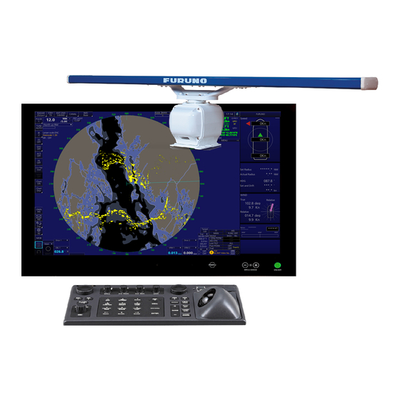
Chart radar
Hide thumbs
Also See for FAR-3230S(-BB):
- Operator's manual (556 pages) ,
- Installation manual (245 pages) ,
- Instruction manual (99 pages)
Table of Contents
Advertisement
Installation Manual
CHART RADAR
Model
SYSTEM CONFIGURATION .......................................................................................... iii
EQUIPMENT LISTS........................................................................................................ vi
1. INSTALLATION.......................................................................................................1-1
1.1 Antenna Unit ......................................................................................................................1-1
1.2 Monitor Unit........................................................................................................................1-8
1.3 Radar Control Unit, Trackball Control Unit.........................................................................1-8
1.4 Power Supply Unit (PSU-014/PSU-015)..........................................................................1-11
1.5 Processor Unit .................................................................................................................1-12
1.6 Sensor Adapter MC-3000S/3010A/3020D/3030D (option) ..............................................1-13
1.7 Intelligent Hub HUB-3000 (option) ...................................................................................1-14
1.8 Switching Hub HUB-100 (option) .....................................................................................1-16
2. WIRING....................................................................................................................2-1
2.1 Overview ............................................................................................................................2-1
2.2 Antenna Unit ......................................................................................................................2-3
2.3 Processor Unit .................................................................................................................2-10
2.4 Power Supply Unit ...........................................................................................................2-21
2.5 Monitor Unit......................................................................................................................2-25
2.6 Sensor Adapters (option) .................................................................................................2-26
2.7 LAN Signal Converter Kit (option)....................................................................................2-43
2.8 Intelligent Hub HUB-3000 (option) ...................................................................................2-47
2.9 How to Extend the Control Unit Cable (option) ................................................................2-48
3. SETTINGS AND ADJUSTMENTS ..........................................................................3-1
3.1 How to Access the Radar Installation Menu ......................................................................3-1
3.2 How to Align the Heading ..................................................................................................3-1
3.3 How to Adjust the Sweep Timing .......................................................................................3-2
3.4 How to Suppress Main Bang .............................................................................................3-3
3.5 Dual Radar Display ............................................................................................................3-3
3.6 Other Settings ....................................................................................................................3-6
4. INPUT/OUTPUT DATA............................................................................................4-1
4.1 Processor Unit ...................................................................................................................4-1
4.2 IEC 61162 Sentences ........................................................................................................4-2
APPENDIX 1 JIS CABLE GUIDE .............................................................................AP-1
APPENDIX 2 ROD TERMINALS ..............................................................................AP-2
APPENDIX 3 DIGITAL INTERFACE ........................................................................AP-7
PACKING LISTS ......................................................................................................... A-1
OUTLINE DRAWINGS ................................................................................................ D-1
INTERCONNECTION DIAGRAMS.............................................................................. S-1
www.furuno.com
All brand and product names are trademarks, registered trademarks or service marks of their respective holders.
Advertisement
Table of Contents

Related Manuals for Furuno FAR-3230S(-BB)


Summary of Contents for Furuno FAR-3230S(-BB)
-
Page 1: Table Of Contents
APPENDIX 1 JIS CABLE GUIDE ................AP-1 APPENDIX 2 ROD TERMINALS ................AP-2 APPENDIX 3 DIGITAL INTERFACE ................AP-7 PACKING LISTS ......................A-1 OUTLINE DRAWINGS ....................D-1 INTERCONNECTION DIAGRAMS................S-1 www.furuno.com All brand and product names are trademarks, registered trademarks or service marks of their respective holders. - Page 2 The paper used in this manual is elemental chlorine free. ・FURUNO Authorized Distributor/Dealer 9-52 Ashihara-cho, Nishinomiya, 662-8580, JAPAN A : APR 2014 Printed in Japan All rights reserved. C1 : FEB . 16, 2015 Pub. No. IME-36180-C1 ( AKMU ) FAR-3230S...
-
Page 3: Far-3230S(-Bb)/Far-3330S
Note: If the antenna unit is installed at a close distance in front of the wheel house, your administration may require halt of transmission within a certain sector of antenna revolution. This is possible. Ask your FURUNO representive or dealer to provide this feature. - Page 4 SAFETY INSTRUCTIONS CAUTION WARNING Do not open the equipment Observe the following compass safe unless totally familiar with distances to prevent deviation of a electrical circuits and service magnetic compass: manual. ELECTRICAL Steering Standard Only qualified personnel are Type SHOCK compass compass allowed to work inside the...
-
Page 5: System Configuration
EPFS meeting the requirements of the IMO resolution MSC.112(73). SDME meeting the requirements of IMO resolution MSC.96(72). The radar may be interconnected via HUB-3000 to other FURUNO processing units having approved LAN ports. Basic configuration is shown with solid line. - Page 6 SYSTEM CONFIGURATION Category of units Antenna units: Exposed to the weather Other units: Protected from the weather Notes 1. The gyrocompass must be type approved for compliance with IMO resolution A.424(XI) (and/ or resolution A.821(19) for installation on HSC). The gyrocompass must also have an update rate that is adequate for the ship’s rate of turn.
-
Page 7: Power Supply
SYSTEM CONFIGURATION Interswitch connection When multiple radars are used, connect, to the EC-3000, the HUB-3000 to the LAN1 port, and HUB-100 to the LAN2 port. This configuration lets each radar as a standalone radar in case of HUB malfunction. 100-115/220-230 VAC 100-115/220-230 VAC ANTENNA UNIT ANTENNA UNIT... -
Page 8: Equipment Lists
EQUIPMENT LISTS Standard Supply Name Type Code No. Remarks Antenna Unit SN36CF-RSB129-107 Control Unit RCU-025 Select Standard type RCU-026 Trackball type Power PSU-014 Select For 24rpm Supply Unit PSU-015 For 42rpm Processor Unit EC-3000 Monitor Unit MU-190 Select For FAR-3230S MU-231 For FAR-3330S Installation... - Page 9 EQUIPMENT LISTS Optional Supply Name Type Code No. Remarks LAN Signal OP03-223-2 Converter Cable OP03-224-2 001-254-400 Extension Kit De-icer Kit OP03-227 001-254-330 Rectifier Unit RU-3424 For 220 VAC RU-1746B-2 Transformer Converts 440 VAC to 100 VAC, for pro- RU-1803 Unit cessor unit Converts 110/115/220/230 VAC to 100 RU-3305-0...
- Page 10 EQUIPMENT LISTS Name Type Code No. Remarks Cable Assy DVI-D/D 001-132-960-10 Between processor and control units, 5 S-LINK 5M DVI-D/D 001-133-980-10 Between processor and control units, S-LINK 10 M 10 m 6TPSH-XH12X2- 001-186-260-10 For RCU-024/025, 5 m L5.0SP1 6TPSH-XH12X2- 001-186-270-10 For RCU-024/025, 10 m L10SP1 6TPSH-XH12X2- 001-186-280-10 For RCU-024/025, 20 m...
- Page 11 EQUIPMENT LISTS About the category sticker This radar meets the requirements in IEC62388 (Marine naviga- Comply with MSC.192(79) tion and radio communication equipment and systems-Ship born CAT 1C CAT 1HC radar-Performance requirements, method of testing and required CAT 2C CAT 2HC test results.) Check the appropriate box on the sticker which is pre-attached on the processor unit, according to your radar’s Sticker for category...
- Page 12 EQUIPMENT LISTS This page is intentionally left blank.
-
Page 13: Installation
INSTALLATION NOTICE Do not apply paint, anti-corrosive sealant or contact spray to coating or plastic parts of the equipment. Those items contain organic solvents that can damage coating and plastic parts, especially plastic connectors. Antenna Unit 1.1.1 Installation considerations • The antenna unit is generally installed either on top of the wheelhouse or on the ra- dar mast, on a suitable platform. - Page 14 1. INSTALLATION • Do not install the antenna where extreme winds may strike the port and starboard sides of the antenna. • Install the antenna unit away from interfering high-power energy sources and TX ra- dio antennas. • Keep the lower edge of the antenna unit above the safety rail by at least 500 mm. •...
- Page 15 1. INSTALLATION 1.1.2 Installation precaution for S-band antenna unit If an S-band antenna unit is mounted near the end of a platform to provide sufficient rotation clearance for the radiator, the antenna unit, because of its weight, swings up and down by ship’s vibration and rolling. This exerts excessive levels of stress at the base of the radiator, which can damage the radiator.
- Page 16 1. INSTALLATION 4. Set the antenna radiator to the radiator bracket from the bottom of the bracket with the eight hex bolts, spring washers and flat washers. The torque must be 49 N•m. Flat washer (eight places) (eight places) Spring washer Bottom view of the bracket Hex bolt (with marine sealant)
- Page 17 1. INSTALLATION 1.1.4 How to hoist the antenna unit The antenna unit may be assembled before hoisting it to the mounting platform. Attach lifting belt slings to the chassis, NOT the antenna radiator, as shown in the figure be- low. There are two methods to hoist the antenna unit.
- Page 18 1. INSTALLATION 1.1.5 How to fasten the antenna unit to the mounting platform 1. Construct a suitable mounting platform referring to the outline drawing at the end of this manual. • The diameter of the mast for fixing the antenna unit platform must be over 250 •...
- Page 19 1. INSTALLATION 5. Using a hex bolt (M6×x25), nut (M6), spring washer (M6) and flat washer (M6), establish the ground system on the mounting platform as shown below. The loca- tion must be within 340 mm of the ground terminal on the antenna unit. Connect the ground wire (RW-4747, 340 mm, supplied) between the grounding point and ground terminal on the antenna unit.
-
Page 20: Monitor Unit
1. INSTALLATION Monitor Unit See the operator’s manual for MU-190 (OMC-44670) or MU-231 (OMC-44690). Keep in mind the following points when selecting a location. Installation considerations • Locate the monitor unit where no framing is installed immediately forward of the monitor. - Page 21 1. INSTALLATION • Fasten the USB cable with the cable Ex. Radar control unit, bottom view RCU-025 tie. Cable routing peg Cable routing peg Cable tie Cable tie USB cable USB cable 1.3.1 Desktop installation How to mount the unit tilted Use the desk fixing plate to mount the unit tilted.
- Page 22 1. INSTALLATION 1.3.2 Installation in a console Use the optional flush mount kit (OP24-24 for RCU-024/025, OP24-27 for RCU-026) to install the control unit in a console. Note: For flush mounting in a panel, the mounting surface must be flat. Do not install the unit on an uneven surface.
-
Page 23: Power Supply Unit (Psu-014/Psu-015)
1. INSTALLATION Power Supply Unit (PSU-014/PSU-015) 1.4.1 Installation considerations The Power Supply Unit can be mounted on a bulkhead or deck. Keep in mind the fol- lowing points when selecting a location. • Locate the unit away from heat sources because of heat that can build up inside the cabinet. -
Page 24: Processor Unit
1. INSTALLATION Processor Unit 1.5.1 Installation considerations Keep in mind the following points when selecting a location. • Locate the processor unit away from heat sources because of heat that can build up inside the cabinet. • Select a location where the vibration is minimal. •... -
Page 25: Sensor Adapter Mc-3000S/3010A/3020D/3030D (Option)
1. INSTALLATION 1.5.2 How to install the processor unit Use four bolts (M6, local supply) to fix the processor unit. 1. Use 10 binding head screws (M4×8, supplied) to attach the chassis bases 1 and 2 to the processor unit. Note: For bulkhead mounting, attach the chassis base 2 so that the notches on it are facing the deck. -
Page 26: Intelligent Hub Hub-3000 (Option)
1. INSTALLATION • Select the mounting location considering the number of the sensor adapters con- nected. A maximum of eight MC-3000S can be connected to a sensor network (for the re- dundant connection:16). A maximum of 10 sensor adapters (MC-3010A/3020D/3030D) can be connected to a MC-3000S. - Page 27 1. INSTALLATION • A magnetic compass will be affected if the adapter is placed too close to the mag- netic compass. Observe the compass safe distances in the "SAFETY INSTRUC- TIONS" (on page i) to prevent interference to a magnetic compass. How to install the HUB-3000 1.
-
Page 28: Switching Hub Hub-100 (Option)
1. INSTALLATION Switching Hub HUB-100 (option) Use the optional Switching Hub HUB-100 to connect sensor networks. This network cannot be connected to the shipborne LAN network. Further do not connect a com- mercial PC to this network, other than for the maintenance. For the installation procedures, see the operator’s manual for HUB-100 (Pub. -
Page 29: Wiring
WIRING Overview Cabling considerations To lessen the chance of picking up electrical interference, avoid where possible rout- ing the antenna cable (power and LAN) near other onboard electrical equipment (ra- dars, TX radio antennas, etc.). Also avoid running the cable in parallel with power ca- bles. - Page 30 2. WIRING Standard wiring A Cat 5e LAN cable (RW-00135) connects between the antenna unit and the power supply unit (PSU). The maximum length of the cables between the Processor Unit and the antenna unit is 80 m. RW-00136 15/30/40/50 m Sub monitor Antenna Unit De-icer...
-
Page 31: Antenna Unit
2. WIRING Antenna Unit Three cables are connected to the antenna unit: antenna cable, cable for the sub mon- itor (option) and power cable for the deicer (option). The procedure shows how to con- nect all cables. Disregard the descriptions for the optional equipment if not applicable. Cable for deicer Cable for antenna Cable for sub monitor... - Page 32 2. WIRING Cable RW-00136 (for a sub monitor) Vinyl tape Armor Sheath Crimp-on lug Shield Sheath Sheath Coaxial cable Cable DPYCY-1.5 (for the optional deicer) Wrap the supplied spiral tube around the power cable for de-icer, starting from the pc board.
- Page 33 2. WIRING 1. Loosen four bolts on the rear cover, then remove the rear cover, Note: The cable for the performance monitor is connected between the rear cover and the RF-TB Board. Detach the cover slowly to prevent damage Performance monitor Performance monitor to the cable and connector.
- Page 34 2. WIRING 6. Unfasten the cable gland for the antenna cable (RW- 00135) and remove the gas- Gasket Gasket ket and three flat washers. Flat washers Flat washers Gland for Gland for antenna cable antenna cable 7. Slide the cable gland, the gasket and three Cable gland Cable gland Flat washer...
- Page 35 2. WIRING 2) Unfasten four bolts to open the front cover. Remove the cover, being careful not to hit the elements on the chassis or radiator. 3) Remove then pass the power cable from the cable entrance. Tighten the ca- ble gland with a hook spaner wrench.
- Page 36 2. WIRING 8) Fasten the two heater elements to the chassis. Fasten the base of the heater with two M5 screws (supplied) coated with marine sealant supplied. Fasten the installation materials to each of the cover bolts. M5 screw M5 screw Fixing Shaft Fixing Shaft SD Heater...
- Page 37 2. WIRING • Antenna cable: Power: TB801 on RF-TB Board (03P9570) Color ORG YEL GRN BLU PPL WHT How to connect wires to WAGO connector Press downward. <Procedure> Terminal 1. Twist the cores. opener 2. Press the terminal opener downward. 3.
-
Page 38: Processor Unit
2. WIRING Processor Unit Note: The interface ports approved for interconnecting navigation equipment are shown in the figure below. For details, see paragraph 2.3.3 "How to select the serial input/output format". J3, J4 For IEC 61162-2 or IEC 61162-1 J5, J6, J7, J8, J9, J10 For IEC 61162-1 Top view of EC-3000 2.3.1... - Page 39 2. WIRING COM2 DVI3 DVI2 MU-190/231 (DVI3: BNCX5-L2000 Cable clamp (DVI2: DVI-D/D S-LINK cable cable) or DVI-BNCX5-L2000 cable) (COM2: DSUB9P-X2-L cable) LAN1 HUB-3000 (DTI-C5E350 VCV cable) Power cable (IEC60320-C13- Ground wire L5M cable) (IV-2sq., LAN2 USB1 local supply) HUB-100/MC-3000S RCU-025/026 (FR-FTPC-CY cable, (TS-20-071-1 cable) within 50m)
- Page 40 2. WIRING How to fabricate the LAN cable Fabricate the LAN cable (FR-FTPC-CY, DTI-C5E350 VCV), as shown below. (Wrap both edges of the armor with vinyl tape.) Make sure the shield of the cable contacts the shell of the modular plug. Armor Cable jacket Inner vinyl sheath...
- Page 41 2. WIRING [Cross cable] [Straight cable] WHT/ORG 1 1 WHT/ORG 1 WHT/GRN WHT/ORG 1 ORG 2 ORG 2 WHT/GRN 3 3 WHT/GRN WHT/GRN 3 3 WHT/ORG BLU 4 BLU 4 WHT/BLE 5 5 WHT/BLE 5 WHT/BLE WHT/BLE 5 GRN 6 GRN 6 WHT/BRN 7 7 WHT/BRN...
- Page 42 2. WIRING 2.3.2 How to connect cables inside the processor unit Fabrication Fabricate the JIS cables (see the Appendix for equivalent cables if not available local- ly) as shown below. Connect the cables to the WAGO connectors on the I/O Board (24P0124) inside the processor unit.
- Page 43 2. WIRING Connection 1. Unfasten four screws (M4×8) to remove the top cover from the processor unit. 2. Unfasten the three bolts circled below to remove the upper plate of the cable clamp. Clamp holes (upper) Unfasten this bolt to use the lower clamp holes.
- Page 44 2. WIRING 5. Bind the cables to the fixing metal in the processor unit with the cable ties (sup- plied). Fixing metal Screws for drain wires of TTYCSLA cables Screws for drain wires of TTYCSLA cables Pass drain wire through shrink tubing (local Pass drain wire through shrink tubing (local supply), attach a crimp-on lug (preattached) supply), attach a crimp-on lug (preattached)
- Page 45 2. WIRING 2.3.3 How to select the serial input/output format How to set the termination resistors Use the jumper blocks JP1 and JP2 on the I/O Board (24P0124) to set the termination resistor J3 and J4 ON or OFF. The default setting is termination resistor: ON. •...
- Page 46 2. WIRING How to select the serial input/output format Use the connectors J3 and J4 to set the input/output format for serial CH1/CH2, from IEC-61162-1 or IEC-61162-2. For connectors J5 to J10, use the TTYCS-1Q or TTYC- SLA-1Q cable. Connector J3 Pin# Signal In/Out...
- Page 47 2. WIRING Connector J6 Pin# Signal In/Out Description Remarks TD4-A Serial CH4, output IEC61162-1 Use TTYCS(LA)-1Q, IEC61162-1 only TD4-B Serial CH4, output IEC61162-1 RD4-H Serial CH4, input IEC61162-1 RD4-C Serial CH4, input IEC61162-1 Connector J7 Pin# Signal In/Out Description Remarks TD5-A Serial CH5, output IEC61162-1 Use TTYCS(LA)-1Q,...
- Page 48 2. WIRING How to set contact input/output The connector J11 can be used for the connection of contact input or voltage input. Refer to the figures shown below to make the wiring which complies with the input specification. Note: The input must not exceed the range of the input voltage, to prevent malfunc- tion.
-
Page 49: Power Supply Unit
2. WIRING Power Supply Unit Wire the unit as shown below. See the interconnection diagram for details. • PSU-014: For antenna of 24 rpm, w/a fan • PSU-015: For antenna of 42 rpm, w/two fans PSU-014 PSU-015 Fuse holder Fuse holders (2 pcs.) 1. - Page 50 2. WIRING 4. As shown below, fabricate the serial cable TTYCS(LA)-1Q and LAN cable that connect between the processor unit and the power supply unit. Also, for retrofit installation, the LAN signal converter is required. For wiring, see "LAN Signal Con- verter Kit (option)"...
- Page 51 2. WIRING 6. Fabricate the antenna cable as shown below. For RW-00135 See "How to fabricate the LAN cable" on page 2-12 for how to attach the LAN ca- ble connector. Power line Armor Vinyl tape LAN cable Sheath Sheath Braided Crimp-on lug (M4) shield...
- Page 52 2. WIRING 9. Connect the power line and the LAN cable as shown below. Connect LAN cable of Connect power line of Connect power line of antenna cable to J102 antenna cable to TB131 antenna cable to TB131 on PSU-CNTL Board. on PSU-TB Board.
-
Page 53: Monitor Unit
2. WIRING Monitor Unit For the wiring of the monitor unit, see the operator’s manual supplied with the monitor unit. Installation consideration <Standard type> • Connect the main monitor to the DVI1 and COM1 ports. • For the sub monitor, connect it to the DVI2 and COM2 port. <VDR connection, ask your dealer>... -
Page 54: Sensor Adapters (Option)
2. WIRING How to open the [INSTALLATION SETTING] menu Turn off the monitor unit. While you hold the DISP key, press the BRILL key to turn on the monitor unit. Press and hold the DISP key for more than five seconds. Note: When the [DVI PWR SYNC] slide switch is ON, turn on the connected external equipment while you press the DISP key to turn on the monitor unit. - Page 55 2. WIRING 2.6.1 MC-3000S Use the LAN cable FR-FTPC-CY cable to connect the MC-3000S and the processor unit. With HUB-100, a maximum of eight MC-3000S can be connected (for the redun- dant connection: 16). Fabrications (unit: mm) TTYCS-1Q cable LAN cable (FR-FTPC-CY) (J9) (J9) (J9)
- Page 56 2. WIRING TTYCSLA-1 cable TTYCS-1 cable Core: 6 Core: 6 Core: 6 Core: 6 Core: 6 Core: 6 Vinyl tape Vinyl tape Vinyl tape Shield (fold back) Shield (fold back) Shield (fold back) Vinyl tape Vinyl tape Vinyl tape (width: 10) (width: 10) (width: 10) (width: 10)
- Page 57 2. WIRING Connections Unfasten four screws to remove the cover. Pass the cables through the clamps and attach the cables to respective connectors. For TTYCSLA cables, attach a shrinking tube (local supply), to drain wire, then use these crimp-on lugs and screws to connect the drain wire here.
- Page 58 2. WIRING How to set input specification (J4 to J9) For connectors J4 to J7, the connections are different depending on the input specifi- cations as shown below. For connectors J8 and J9, the signal names corresponding to the pins are shown. Connector J4 Signal Pin #...
- Page 59 2. WIRING Connector J6 Pin # Signal name In/Out Remarks IEC61162-2 IEC61162-1 TD3-A Serial CH3, output IEC61162-1/2 TTYCS(LA)-4 TTYCS(LA)-4 TD3-B Serial CH3, output IEC61162-1/2 RD3-A Serial CH3, input IEC61162-2 No connection RD3-B Serial CH3, input IEC61162-2 ISOGND3 Isolation, GND (CH3) RD3-H Serial CH3, input IEC61162-1 No connection TTYCS(LA)-4...
- Page 60 2. WIRING Case gasket OP24-28 The optional kit OP24-28 protects the connectors on the MC-3000C to waterproofing standard IPX2. Case gasket (type: OP24-28, code no.: 001-169-970) Name Type Code No. Remarks Case packing (serial) 24-014-2051 100-367-880-10 2 For MC-3000S 1. Unfasten four binding screws to remove the cover from the adapter. Binding screw Cover 2.
- Page 61 2. WIRING 2.6.2 MC-3010A/3020D/3030D • MC-3010A: Inputs analog signal. To use MC-3010A as current input, connect short pins to each terminals. • MC-3020D: Inputs digital signal (8ch contact input). Contact or voltage input is se- lectable (contact input requires short pins). •...
- Page 62 2. WIRING Connection For TTYCSLA cables, pass the drain wire through shrink tubing, then attach these crimp-on lugs and screws to connect drain wires to chassis. IV-1.25sq. (Local supply) IV-1.25sq. (Local supply) IV-1.25sq. (Local supply) TTYCS-1/ TTYCS-1/ TTYCS-1/ TTYCSLA-1 TTYCSLA-1 TTYCSLA-1 MC1.5-W-L cable MC1.5-W-L cable...
- Page 63 2. WIRING Input method (MC-3010A only) Select the method of the analog data input, power voltage or power current. Note 1: The input must not exceed the range of the input voltage, to prevent malfunc- tion. • Setting for voltage input: -10V to +10V or 0 to 10V (depending on the setting) •...
- Page 64 2. WIRING Connector J4 Pin # Signal name In/Out Description Power voltage Power current AN2_IN Analog 2 input TTYCS(LA)-1 AN2_GND Analog 2 GND CURR2_JP1 Analog 2 input, power current/ Pin #3-#4: open Pin #3-#4: short voltage setting jumper 1 CURR2_JP2 Analog 2 input, power current/ voltage setting jumper 1 Connector J5...
- Page 65 2. WIRING Connector J3 ACK1 ACK1 ACK2 ACK2 Pin # Signal name In/Out Remarks contact voltage contact voltage DC12V_OUT ACK1 In Pin #1-#2: No connec- short tion DIGI_IN1 MPYC-12 Depending on ACK1 input DIGI_RTN1 MPYC-12 No connec- (DC12V) tion DC12V_OUT ACK2 In Pin #1-#2: No connec-...
- Page 66 2. WIRING Connector J6 ACK7 ACK7 ACK8 ACK8 Pin # Signal name In/Out Remarks contact voltage contact voltage DC12V_OUT ACK7 In Pin #1-#2: No connec- short tion DIGI_IN7 MPYC-12 Depending on ACK8 in- DIGI_RTN7 MPYC-12 GND (DC12V) In No connec- tion DC12V_OUT ACK8 In...
- Page 67 2. WIRING Connector J6 Signal Alarm7 NO Alarm7 NC Alarm8 NO Alarm8 NC Remarks name Alarm7 MPYC-12 No connection COM7 MPYC-12 No connection Alarm8 MPYC-12 No connection COM8 MPYC-12 No connection Case gasket OP24-29 The optional kit OP24-29 protects the connectors on the MC-3010A/3020D/3030D to waterproofing standard IPX2.
- Page 68 2. WIRING 2.6.3 How to set jumper blocks in the sensor adapters MC-3000S See the jumper blocks on the MC-CS Board (24P0114) referring to the tables that fol- low. J14 J22 J23 J15 J16 J17 J20 J21 MC-CS Board (24P0114) Rotary switch S2: Use the rotary switch (S2) to set the Modbus address when setting connectors J4/J5 to Modbus.
- Page 69 2. WIRING <Terminal resistor OFF> • When setting the terminal other than starting/ending for the multipoint (CH1 to 4). • When setting the terminal other than starting/ending for Modbus (CH1/CH2) Jumper block J14 Connector J4 (CH1) SHORT Termination resistor: ON (default setting) OPEN OPEN Termination resistor: OFF...
- Page 70 2. WIRING MC-3010A/3020D/3030D This paragraph shows how to set the MC-ANLG Board (24P0115, for MC-3010A), MC-DIN Board (24P0116, for MC-3020D) and MC-DOUT Board (24P0117, for MC- 3030D). Rotary switch U18: Use the rotary switch (U18) to set the MODBUS address with a digit of number from “0”.
-
Page 71: Lan Signal Converter Kit (Option)
2. WIRING LAN Signal Converter Kit (option) Two LAN Signal Converters (for antenna unit and PSU) allow the use of existing an- tenna cable RW-4873/6895/9600 in the case of a retrofit. Kit contents (Type: OP03-223-2, Code no.: 001-254-370) Name Type Code no. - Page 72 2. WIRING 2.7.2 Installation in the antenna unit Dismount the transceiver unit. See paragraph 2.2.2 for the procedure. 1. Set the M_S switch on the converter to the S (Slave) position. 2. Fasten the converter. Loosely fasten the Fasten the converter inside the converter to its transceiver unit with...
- Page 73 2. WIRING 8. Connect the coaxial cable from the converter to the BNC case, passing through the locking wire saddle. Coaxial cable Coaxial cable Coaxial cable Fasten the BNC case to the rail inside Connect the coaxial cable to the BNC case, the antenna unit with two screws.
- Page 74 2. WIRING 4. Connect the LAN, power and co- LAN cable LAN cable axial cables as shown below. Power cable Power cable • Pass the LAN cable through J107 J107 the four locking wire saddles then connect it to the LAN port on the converter.
-
Page 75: Intelligent Hub Hub-3000 (Option)
2. WIRING Intelligent Hub HUB-3000 (option) Fix the LAN cables connected to the cable clamp with the cable ties (supplied). Power port Power Fail DPYC-1.5 cable DPYC-1.5 cable Ground wire (IV-1.25sq., supplied) LAN cable No use. LAN port To gateway network (ECDIS, radar, etc.) Attach the LAN cap (supplied) to the unused connector holes to meet waterproofing standard IPX2. -
Page 76: How To Extend The Control Unit Cable (Option)
2. WIRING How to Extend the Control Unit Cable (option) To extend the length of the cable between a control unit and the processor unit, use the optional cable assy 6TPSH-XH12X2-LxxSP1 (for RCU-024) or 6TPSH-XH12X2- LxxSP2 (for RCU-026). You can select the cable length among 10, 20 and 30 m. 2.9.1 RADAR control unit (RCU-025) 1. - Page 77 2. WIRING 9. Unfasten the three bolts circled in the figure below to remove the cable clamp (up- per). Clamp holes (upper) Unfasten this bolt to use the lower clamp holes. Clamp holes (lower) Unfasten these three bolts to remove the upper plate. 10.
- Page 78 2. WIRING 2.9.2 Trackball control unit (RCU-026) 1. Unfasten four binding screws (M3×8) from the bottom of the control unit, and a pan head screw (M3×8) and flat washer from the back of the control unit to remove the cover. Note: Remove the cover slowly to prevent damage to the cables connected to the circuit board in the control unit.
- Page 79 2. WIRING 5. Fasten the shield of the cable assy with the cable clamp (removed at step 2), then connect the connector at the end of the cable assy to the J1 on the circuit board. Note: When clamping, the shield part of the cable must not touch the circuit board. Shield Cable assy Cable clamp...
- Page 80 2. WIRING This page is intentionally left blank. 2-52...
-
Page 81: Settings And Adjustments
SETTINGS AND ADJUSTMENTS Note: After completing the settings and adjustments, copy the setting data to a USB flash memory, referring to section 23.2 in the Operator’s Manual. This will easy allow restoration of setting data after the SPU Board is replaced, etc. How to Access the Radar Installation Menu The [RADAR INSTALLATION] menu has vari- ous items for adjustment of the radar. -
Page 82: How To Adjust The Sweep Timing
3. SETTINGS AND ADJUSTMENTS 1. Select a stationary target echo at a range between 0.125 and 0.25 NM, preferably near the heading line. 2. Operate the EBL control to bisect the target echo. 3. Read the target bearing. 4. Measure the bearing of the stationary target on a navigation chart and calculate the difference between the actual bearing and apparent bearing on the radar screen. -
Page 83: How To Suppress Main Bang
3. SETTINGS AND ADJUSTMENTS How to Suppress Main Bang Main bang is the clutter at the center of the screen that you typically see on the radar display, and it may mask close-in targets. If main bang appears at the screen center, suppress it as follows. - Page 84 3. SETTINGS AND ADJUSTMENTS 3.5.2 How to set the width and length for the picture from the exter- nal radar If two FAR-3xx0 series radars are to be used for the dual radar display, set the same display area on each radar to ensure proper performance. 1.
- Page 85 3. SETTINGS AND ADJUSTMENTS 5. Use the scrollwheel to set START and ANGLE, referring to the description and ex- ample below. Spin the scrollwheel to set and push it to confirm. A solid green line marks the dual radar display area. Width of sector START ANGLE...
-
Page 86: Other Settings
3. SETTINGS AND ADJUSTMENTS Note 2: The dual radar display is designed to be used with two FAR-3xx0 series radars. Other makes or models can be used, however performance may vary. 4. Press the MENU key to close the menu. Other Settings [ECHO ADJ] menu [VIDEO LEVEL ADJ]: Adjust the cable attenu-... - Page 87 3. SETTINGS AND ADJUSTMENTS normal rotation speed to 36 rpm and switches the rotation speed to 42 rpm when the short pulse is selected. Note: Select [OFF] at [ANT SW] to prevent antenna rotation. [ANT STOPPED] pre- vents transmission while the antenna is stopped in STBY. [INSTALLATION] menu IMO- and A-type radars B-type radar...
- Page 88 3. SETTINGS AND ADJUSTMENTS 2. Set the radar controls as shown below. Range: 24 NM A/C RAIN: OFF (turn off manually) Pulse Length: Long Echo Averaging (EAV): OFF A/C SEA: OFF (turn off manually) Video Contrast: 2-B 3. Adjust the GAIN control so that a slight amount of white noise appears on the screen.
- Page 89 3. SETTINGS AND ADJUSTMENTS [TTM/TTD REFERENCE]: Set the output format (bearing) of tracked targets. REL (Target bearing from own ship, degree relative, target course, degree relative), or TRUE (Target bearing, degree true, target course, degree true). [NUMBER OF TT]: Set the number of targets that can be acquired, [100] or [MAX] (200).
- Page 90 3. SETTINGS AND ADJUSTMENTS [OTHERS] menu [DEMO ECHO]: Select the type of demonstra- tion echo to use. [EG] (Echo Generator), [TT- TEST] or [PC]. Select [OFF] to deactivate the demonstration echo feature. [EAV W/O GYRO]: The each averaging feature can be used without a gyrocompass. Select [ON] to use the feature without a gyrocompass.
-
Page 91: Input/Output Data
Gyrocompass meeting the requirements of the IMO resolution A.424(XI). EPFS meeting the requirements of the IMO resolution MSC.112(73). SDME meeting the requirements of IMO resolution MSC.96(72). The radar may be interconnected via HUB-3000 to other FURUNO processing units having approved LAN ports. Processor Unit Input and output data are shown in the table below. -
Page 92: Iec 61162 Sentences
4. INPUT/OUTPUT DATA IEC 61162 Sentences Input sentence and sentence priority Data Sentence priority Acknowledge alarm AIS base station addressed channel management command AIS addressed and binary broadcast acknowledgement Datum Depth DPT>DBT Heartbeat supervision report Heading (true) THS>HDT Position GNS>GGA>RMC>GLL Set alarm state Set and drift CUR>VDR... -
Page 93: Appendix 1 Jis Cable Guide
EX: TTYCYSLA - 4 MPYC - 4 TTYCSLA-4 # of cores Designation type Designation type # of twisted pairs The following reference table lists gives the measurements of JIS cables commonly used with Furuno products: Cable Core Core Cable Diameter Diameter... - Page 94 APPENDIX 2 ROD TERMINALS MC-3000S, MC-CS Board (24P0114) Connector # Pin # Signal name Rod terminal to use Connected cable 24V_VOUT AI 0.34-6 TQ (blue) 24V_GND MODBUS-A MC1.5-W-Lxxx MODBUS-B AI 0.14-8 GY (gray) Connector # Pin # Signal name Rod terminal to use Connected cable 24V_IN AI 1.5-6 BK (black)
-
Page 95: Appendix 2 Rod Terminals
APPENDIX 2 ROD TERMINALS Connector # Pin # Signal name Rod terminal to use Connected cable TD4-A TD4-B RD4-A TTYCS-4 RD4-B AI 0.75-6 GY (gray) TTYCSLA-4 ISOGND4 RD4-H RD4-C Connector # Pin # Signal name Rod terminal to use Connected cable TD5-A TD5-B TTYCS-1Q... - Page 96 APPENDIX 2 ROD TERMINALS Connector # Pin # Signal name Rod terminal to use Connected cable AN2_IN AN2_GND TTYCS-1 AI 0.75-6 GY (gray) TTYCSLA-1 CURR2_JP1 CURR2_JP2 Connector # Pin # Signal name Rod terminal to use Connected cable AN3_IN AN3_GND TTYCS-1 AI 0.75-6 GY (gray) TTYCSLA-1...
- Page 97 APPENDIX 2 ROD TERMINALS Connector # Pin # Signal name Rod terminal to use Connected cable DV12V_OUT5 DIGI_IN5 DIGI_RTN5 AI 1-6 RD (red) MPYC-12 DC12V_OUT6 DIGI_IN6 DIGI_RTN6 Connector # Pin # Signal name Rod terminal to use Connected cable DV12V_OUT7 DIGI_IN7 DIGI_RTN7 AI 1-6 RD (red)
- Page 98 APPENDIX 2 ROD TERMINALS Connector # Pin # Signal name Rod terminal to use Connected cable COM3 AI 1-6 RD (red) MPYC-12 COM4 Connector # Pin # Signal name Rod terminal to use Connected cable COM5 AI 1-6 RD (red) MPYC-12 COM6 Connector #...
-
Page 99: Appendix 3 Digital Interface
APPENDIX 3 DIGITAL INTERFACE Digital Interface Input sentence ABK, ACK, ACM, ACN, ALR, CUR, DBT, DPT, DTM, GGA, GLL, GNS, HBT, HDT, MTW, MWV, RMC, THS, VBW, VDM, VDO, VDR, VHW, VTG, ZDA Output sentences ABM, ACK, ALC, ALF, ALR, ARC, BBM, EVE, HBT, OSD, RSD, TLB, TTD, TTM, VSD Data reception Data is received in serial asynchronous form in accordance with the standard referenced in IEC 61162-2 or IEC 61162-1 Ed.4. - Page 100 APPENDIX 3 DIGITAL INTERFACE ACM, ACN - Alert command $**ACM,hhmmss.ss,aaa,x.x,x.x,ca,a*hh<CR><LF> $**ACN,hhmmss.ss,aaa,x.x,x.x,ca,a*hh<CR><LF> 1. Time (hh=00 to 23, mm=00 to 59, ss.ss=00.00 to 60.99), null 2. Manufacturer mnemonic code (3 digit alphanumeric code), null 3. Alert identifier (0 to 9999999) 4. Alert instance (1 to 999999), null 5.
- Page 101 APPENDIX 3 DIGITAL INTERFACE DTM - Datum reference $**DTM,ccc,a,x.x,a,x.x,a,x.x,ccc,*hh<CR><LF> 1 2 3 4 5 6 7 1. Local datum (W84=WGS84 W72=WGS72 S85=SGS85, P90=PE90 2. Local datum subdivision code (NULL or one character) 3. Lat offset, min (0 - 59.99999) 4. N/S 5.
- Page 102 APPENDIX 3 DIGITAL INTERFACE HBT - Heartbeat supervision sentence $**HBT,x.x,A,x*hh<CR><LF> 1 2 3 1. Configured repeat interval (00.0 to 99.9(s)) 2. Equipment status (A=Normal V=System fail) 3. Sequential sequence identifier (0 to 9) HDT - Heading, true $**HDT, xxx.x,T*hh<CR><LF> 1. Heading, degrees (0.00 to 360.00) 2.
- Page 103 APPENDIX 3 DIGITAL INTERFACE VBW - Dual ground/water speed $**VBW,x.x,x.x,x,x.x,x.x,x,x.x,x,x.x,x,*hh<CR><LF> 1 2 3 4 5 6 7 8 9 10 1. Longitudinal water speed, knots (-99.949 - 99.949) 2. Transverse water speed, knots (-99.949 - 99.949, null) 3. Status: water speed, A=data valid V=data invalid 4.
- Page 104 APPENDIX 3 DIGITAL INTERFACE VTG - Course over ground and ground speed $**VTG,x.x,T,x.x,M,x.x,N,x.x,K,a,*hh <CR><LF> 1 2 3 4 5 6 7 8 9 1. Course over ground, degrees (0.00 - 360.00) 2. T=True (fixed) 3. Course over ground, degrees (No use) 4.
- Page 105 APPENDIX 3 DIGITAL INTERFACE ALF - Alert sentence $**ALF,x,x,x,hhmmss.ss,a,a,a,aaa,x.x,x.x,x.x,x,c--c,*hh<CR><LF> 1 2 3 5 6 7 8 9 10 11 12 13 1. Total number of ALF sentences this message (1, 2) 2. Sentence number (1, 2) 3. Sequential message identifier (0 to 9) 4.
- Page 106 APPENDIX 3 DIGITAL INTERFACE OSD- Own ship data $**OSD,53.21,A,57.89,R,12.52,R,45.67,6.78,N*hh<CR><LF> 1. Heading, degrees true (0.00 - 359.99, null) 2. Heading status (A=data valid, V=data invalid) 3. Vessel course, degrees true (0.00 - 359.99, null) 4. Course reference (B/M/W/R/P, null) B=Bottom tracking log M=Manually entered W=Water referenced R=Radar tracking (of fixed target)
- Page 107 APPENDIX 3 DIGITAL INTERFACE TTM - Tracked target message $RATTM,05,12.34,23.4,R,45.67,123.4,T,1.23,8.23,N,c--c,T,R,hhmmss.ss,M*hh<CR><LF> 9 10 11 12 13 1. Target number (00 to 999) 2. Target distance from own ship (0.000 - 99.999) 3. Bearing from own ship,degrees (0.0 - 359.9) 4. True or Relative (T) 5.
- Page 108 APPENDIX 3 DIGITAL INTERFACE Serial Interface Processor Unit: IEC 61162-1 input Processor Unit: IEC 61162-2/1 input/output Sensor Adapter: IEC 61162-2/1 input/output Sensor Adapter: IEC 61162-1 input TD-A 470 Ω RD-H TD-B PC-400 LTC1535 ISOGND RD-C RD-A RD-B 110 Ω* 470 Ω RD-H Processor Unit: IEC 61162-1 output PC-400...
- Page 120 24/Mar/2014 H.MAKI...
- Page 121 24/Mar/2014 H.MAKI...
- Page 125 D-10...
- Page 126 D-11...
- Page 127 D-12...
- Page 128 D-13...
- Page 129 D-14...
- Page 130 D-15...
- Page 131 D-16...
- Page 132 D-17...
- Page 133 D-18 Y.NISHIYAMA 13/Jan/2012...
- Page 134 D-19 Y.NISHIYAMA 13/Jan/2012...
- Page 135 D-20 Y.NISHIYAMA 13/Jan/2012...
- Page 136 D-21 Y.NISHIYAMA 13/Jan/2012...
-
Page 137: Interconnection Diagrams
空中線ケーブルRW-9600で接続する場合 CONNECTION WITH ANTENNA CABLE RW-9600 空中線部 TB803 RW-00136,15/30/40/50m,φ20 パフォーマンスモニター ANTENNA UNIT チャ 副指示器 PERFORMANCE MONITOR PM-52A RSB-129 アカ SUB MONITOR OP_HD RSB-129 ダイ キ OP_BP シロ クロ OP_TRIG DC12V TB804 HMC-200CE-A COAX. CABLE RW-4747 IV-3.5sq. LAN同軸変換器 LAN-SIGNAL CONVERTER KIT HMC-200CE-A DC12V J101... - Page 138 空中線部 TB803 RW-00136,15/30/40/50m,φ20 パフォーマンスモニター ANTENNA UNIT チャ 副指示器 PERFORMANCE MONITOR PM-52A RSB-129 アカ SUB MONITOR OP_HD ダイ キ OP_BP シロ クロ BLK OP_TRIG TB804 COAX. CABLE RW-4747 IV-3.5sq. J101 STP(CAT5e) CABLE IEC61162-1/2 IEC61162-1 MAX.30m 制御部 03P9566 空中線電源部 24P0124 PROCESSOR UNIT TB132 POWER SUPPLY UNIT TTYCS(LA)-1Q...
- Page 139 6/Jan/2014 H.MAKI 電子署名者 : Maki DN: cn=Maki, c=JP - 日本, o=FURUNO, ou=technicaldocume nt, email=hiromasa. maki@furuno.co.jp 日付 : 2014.01.06 16:36:08 +09'00'...
Need help?
Do you have a question about the FAR-3230S(-BB) and is the answer not in the manual?
Questions and answers