
Subscribe to Our Youtube Channel
Related Manuals for Panasonic KS1


Summary of Contents for Panasonic KS1
- Page 1 Phone: 800.894.0412 - Fax: 888.723.4773 - Web: www.clrwtr.com - Email: info@clrwtr.com...
- Page 2 Copyright and trademark ● Panasonic Electric Works, Ltd. owns the copyright of this manual. ● We stiffly refuse the reproduction of without permission from this manual. ● Modbus Protocol is a communication protocol that the Modicon Inc.developed for PLC.
- Page 3 Introduction Thank you very much indeed for purchasing “KS1 Signal Converter”. In this manual, we explain the usage of “KS1 Signal Converter” in detail. Please use it correctly after understanding the content enough. Phone: 800.894.0412 - Fax: 888.723.4773 - Web: www.clrwtr.com - Email: info@clrwtr.com...
-
Page 4: Table Of Contents
Table of Contents Cautions before using ..........................ⅰ Chapter 1 Unit’s Features and Structure....................... 1 1-1 Features..............................1 1-2 Unit’s Name and Part Numbers....................... 1 1-2-1 Main unit............................1 1-2-2 Accessories ..........................1 1-2-3 Options............................1 1-2-4 Tool software ..........................1 Chapter 2 Parts Name and Working ...................... -
Page 5: Cautions Before Using
Cautions before using ■ Installation environment ◇Do not use the Unit in the following environments. ・Where the unit will be exposed to direct sunlight and where the ambient temperature is outside the range of 0 to 55 °C. ・Where the ambient humidity is outside the range of 30 to 85 % RH (at 20℃ non-condensing) and where condensation might occur by sudden temperature changes ・Where inflammable or corrosive gas might be produced ・Where the unit will be exposed to excessive airborne dust or metal particles... -
Page 6: Chapter 1 Unit's Features And Structure
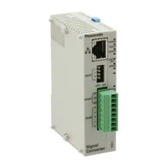
Unit’s Features and Structure 1-1 Features KS1 signal converter is a signal converter of the DIN rail installation type that converts serial-communication data (RS232C, RS485) into Ethernet data (Ethernet). Data exchange by personal computers or PLC etc. is achieved by converting serial-communication data to Ethernet data and connecting directly with LAN cable. -
Page 7: Chapter 2 Parts Name And Working
Chapter 2 Parts Name and Working 2-1 Parts Names ①Status indicator LED Lighting or blinking according to the unit status ・POWER: Lighting when power on ・RESET: Lighting while pressing ⑥ reset switch ・ERROR: Blinking when error occurs with this unit ②Input / Output indicator Lighting or blinking according to LAN communication status ・LINK/ACT: Lighting when the link is approved... -
Page 8: Chapter 3 Wiring And Installing Space
Chapter 3 Wiring and Installing Space 3-1 Main unit terminal arrangement Be sure to wire correctly according to the terminal arrangement and wiring diagrams. ⑦LAN Connector Connector: RJ45 Cable: UTP (Category 5 or more) This unit recognizes automatically the cable, cross or straight. Select cable according to the connected devices. -
Page 9: Wiring Diagrams
3-2 Wiring Diagrams Signal Converter Connected device RS232C RS232C + - + RS485 RS485 + - - Cautions for wiring (1)Terminal fastening torque should be 0.22 to 0.25 N・m. (Use terminal driver AFP0806.) (2) Use wire with its cross section of 0.3~1.0mm (AWG#22~16) for the terminal. -
Page 10: Installing Space
3-4 Installing space ・Leave the unit at least 50mm from both the wiring duct and the other device to allow heat radiation and unit replacement as shown below. 50mm or more 50mm or more Other device or Panel ・Leave the unit at least 100mm from both a device that 100mm or more generate noise radiation, and the power line in order to avoid adverse affects of noise radiation and heat. -
Page 11: Chapter 4 How To Install
Chapter 4 How to Install 4-1. Install to DIN rail You can install Signal Converter to DIN rail easily. Procedure: 1. Hook the upper hook of main unit on DIN rail like 1 2. With supporting the upper hook, push main unit to DIN rail like 2 and fix the lower hook. Mount Panel Signal Converter DIN rail... -
Page 12: Install By Using Fp0 Slim Type Mounitng Plate
4-3. Install by using FP0 Slim type mounitng plate Please use M4 screws to install FP0 slim type mounting plate (AFP0803) in the mounting plate. FP0 Slim type mounting plate Screw Screw 6 mm Procedure: 1. Hook the upper hook of main unit on FP0 Slim type mounting plate like 1. 2. -
Page 13: Install By Using Fp0 Flat Type Mounitng Plate
4-4. Install by using FP0 Flat type mounitng plate Please use M4 screws to install FP0 flat type mounting plate (AFP0804) in the mounting plate. FP0 Flat type mounting plate Screws Procedure: 1. Please lift the expanding hooks of the upper surface and the bottom. 2. -
Page 14: Chapter 5 Setting
A personal computer with Windows and Ethernet interface is required in order to set Signal converter. You can download the software from the homepage of Panasonic Electric Works, Ltd. http://panasonic-denko.co.jp/ac/e/dl/software-info/common/tol_configwd.jsp Download “Configurator WD” (IP Address search tool) V1.21 or more and install in a PC according to the below procedure. - Page 15 [Next]. Select program folder install Configurator WD and click [Next]. Confirm the completion of the installation. After complete the installation, click [start]-[program]-[Panasonic EW Control]-[Configurator WD] to start “Configurator WD”. Phone: 800.894.0412 - Fax: 888.723.4773 - Web: www.clrwtr.com - Email: info@clrwtr.com...
-
Page 16: Set And Change Ip Address
5-2 Set and Change IP Address All devices connected with Ethernet network are required their own IP address. 192.168.1.5 is initially allocated to Signal converter as IP address. If you want to change IP address, change here according to the procedure. Start Configurator WD and click the search button in order to search units. -
Page 17: Communication Setting
5-3 Communication Setting You can set communication conditions by 2 methods, using the communication set switches on the front of main unit and using the setting software (Configurator WD). 5-3-1 Set by the communication set switches on the unit Use ④Communication set switch 1 and ⑤Communication set switch 2 to set communication setting. ④Communication set switch 1 ⑤Communication set switch 2 MODE... -
Page 18: Set By Setting Tool Configurator Wd
You can download the setting tool software “Configurator WD” from our web site. http://panasonic-denko.co.jp/ac/e/ Use “Configurator WD” ver. 1.42 or more for KS1 signal converter ver. 1.03 or more, that supports Modbus TCP. Please refer to the help in Configurator WD for the way to set. - Page 19 This is the display when you select MODBUS TCP (RTU). This it the display when you select MODBUS TCP (ASCII). Set action mode of PLC/PC for Ethernet network. At present, you can select only Server mode. Phone: 800.894.0412 - Fax: 888.723.4773 - Web: www.clrwtr.com - Email: info@clrwtr.com...
- Page 20 Set Baud rate of serial communication. Default setting is 9600bps. You can set it for COM1 (RS232C) and COM2 (RS485) individually. When setting by hardware (communication set switches), the settings of COM1 and COM2 are common. Set Data length of serial communication. At present, it fixes 8bit. Set Parity of serial communication.
- Page 21 Set Stop bit of serial communication. Default setting is “1 bit”. Set End codes of serial communication. Default setting is CR. Select from CR, CR+LF and None. Set COM Timeout of serial communication. Default setting is 5000ms (5s). It means the time to wait responses from the devices connected by RS232C and RS485. After passing the set time, it finishes the communication via the serial port.
- Page 22 COM Timeout can be set 300 seconds or less by checking the box. Uncheck the box : 10-60000msec possible to set every millisecond Check the box : 61-300sec possible to set every second Set Source Port No. of serial communication devices at server mode. Default setting is 9094 for RS232C and 9095 for RS485.
- Page 23 When “502” is set to COM1, set “9095” to COM2 and when “502” is set to COM2, set “9094” to COM1. And confirm that there is not the port number repetition from a client. KS1 Signal Converter can connect 3 devices as RS232C server and 3 devices as RS485 server. Max connected devices as server side is 6 connections.
-
Page 24: Chapter 6 Specifications
Chapter 6 Specifications 6-1 Main unit Rated operating voltage 24V DC Rated power consumption 2.4VA Allowable operating voltage range 21.6~26.4V DC (90%~110% of rated operating voltage) Allowable momentary 10ms power-off time 0 ~ +55℃ Ambient temperature Ambient humidity 30~85%RH (at 20℃ non-condensing) Between the isolated circuits: 500V/1min Breakdown voltage(initial) -
Page 25: Communication Specifications Interface: Ethernet
3) The time from when it comes no connection after establish TCP connection to cut TCP connection when connect by MODBUS TCP. If set to “0”, KS1 Signal converter keeps TCP connection until when MODBUS TCP client cut correctly. However, without transmission for 2 hours, it cut TCP connection. -
Page 26: Outline Of Modbus Tcp And Transmission Format
This shows the command to read out 1 byte data designated by 238D send from MODBUS TCP client to serial communication device number 01. ②Example of MODBUS RTU Command from MODBUS TCP server (KS1 Signal converter) to Serial slave unit... - Page 27 00 to FF Fix to 0000 ・This shows the response to send from MODBUS TCP server (KS1 Signal converter) to MOSBUS TCP client after conversion 2 bytes data 0128(Hex) designated 238D send from serial communication device number 01 to transmit data.
-
Page 28: Chapter 7 Error Indication And Clear Error
Chapter 7 Error indication and Clear Error 7-1 Error indication You can see some errors’ contents by Configurator WD status error code. Error code Item Contents 0x26 ROM error Flash ROM setting read failure 0x21 RAM error RAM read failure 0x60 System error 1 Task formation failure... -
Page 29: Revision History
First edition August, 2007 ARCT1F437E-1 Second edition Added the explanation of the new features of the setting Timeout along with the upgrade of KS1 Signal Converter and Configurator WD. October, 2007 ARCT1F437E-2 Third edition Added the explanation of the new features of the setting Ethernet Timeout along with the upgrade of KS1 Signal Converter.
Need help?
Do you have a question about the KS1 and is the answer not in the manual?
Questions and answers