Table of Contents
Advertisement
Quick Links
Download this manual
See also:
Installation Manual
Advertisement
Table of Contents

Related Manuals for Panasonic BY-HPE11KTA


Summary of Contents for Panasonic BY-HPE11KTA
- Page 1 Operating Instructions Coaxial - LAN Converter with PoE function Indoor Use Only BY-HPE11KTA Model No. Attached Installation Guide Before attempting to connect or operate this product, please read these instructions carefully and save this manual for future use.
- Page 2 Introduction Introduction About the user manuals • There are 2 sets of operating instructions for this unit as follows. – Installation Guide: Explains how to install and connect devices. – Operating Instructions (PDF): Explains how to perform the settings and how to operate this unit.
-
Page 3: Table Of Contents
Table of Contents Table of Contents Main Unit .....................4 Camera Adaptor (BY-HPE11R) ................4 Center Adaptor (BY-HPE11H) ................6 Understanding the Indicators .................7 Resetting the Unit ..................8 Resetting Camera Adaptors ................8 Resetting Center Adaptors ................9 Adaptor Maintenance Screen ..............10 Accessing the Maintenance Screen .............11 3.1.1 Temporarily Changing the Computer’s IP Address ........11 3.1.2... -
Page 4: Main Unit
1 Main Unit 1 Main Unit 1.1 Camera Adaptor (BY-HPE11R) Front view A Indicator Displays the status of the camera adaptor (see page 7). B PoE switch Turns the PoE function ON/OFF. The default setting is [ON]. IMPORTANT • When using the camera adaptor’s PoE function to supply power to a network camera, set the PoE switch to [ON]. - Page 5 1 Main Unit Rear view A Used when attaching the camera adaptor to a ceiling or wall with screws (see 2.1 Mounting the Camera Adaptor in the Installation Guide). B Used when attaching the safety wire (see 2.1 Mounting the Camera Adaptor in the Installation Guide).
-
Page 6: Center Adaptor (By-Hpe11H)
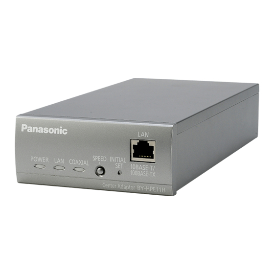
1 Main Unit 1.2 Center Adaptor (BY-HPE11H) Front view A Indicators Displays the status of the center adaptor (see page 7). B SPEED button Used when measuring the speed between adaptors (see 3.2 Connections in the Installation Guide). C INITIAL SET button Used to reset the center adaptor to its factory default settings (see page 9). -
Page 7: Understanding The Indicators
1 Main Unit 1.3 Understanding the Indicators The light indicators change depending on the operating status of the camera and center adaptors. Camera adaptor Indicator Light Status Meaning Green (lit) The camera adaptor is connected to the center adaptor. Orange (lit) The camera adaptor is activating. -
Page 8: Resetting The Unit
2 Resetting the Unit 2 Resetting the Unit Reset the unit when reselling, disposing, or sending it for repairs. 2.1 Resetting Camera Adaptors Reset the camera adaptor when it is connected to the center adaptor with a coaxial cable, and the center adaptor is connected to the power outlet. 1. -
Page 9: Resetting Center Adaptors
2 Resetting the Unit 2.2 Resetting Center Adaptors 1. Press the center adaptor’s INITIAL SET button (A) for about 3 seconds with a pointed object. • All the indicators (B) will start flashing green. 2. All of the center adaptor’s indicators (B) are lit green. •... -
Page 10: Adaptor Maintenance Screen
IP address and network settings to their original values. • If you plan to update the adaptor’s firmware, download the latest version of the adaptor’s firmware from the Panasonic support site (http://panasonic.net/pss/security/products/coax/index.html) and save it on the computer before you change the IP address of the computer. -
Page 11: Accessing The Maintenance Screen
3 Adaptor Maintenance Screen 3.1 Accessing the Maintenance Screen 3.1.1 Temporarily Changing the Computer’s IP Address Temporarily change the IP address assigned to your computer to access the adaptor’s maintenance screen. The procedure for changing the IP address differs depending on the operating system used. - Page 12 3 Adaptor Maintenance Screen 5. Select [Use the following IP address], then click [OK] after entering the IP address (192.168.249.***) and Subnet mask (255.255.255.0). For the IP address, ***=1-254. However, 249 cannot be used. 6. Click [Close] to exit the [Local Area Connection Properties] screen. IMPORTANT •...
-
Page 13: Accessing The Maintenance Screen
3 Adaptor Maintenance Screen 3.1.2 Accessing the Maintenance Screen Follow the procedure below after you have changed the IP address of the computer. 1. Connect the adaptor (A: camera adaptor or center adaptor) and computer (C) using a LAN cable (B). When accessing the camera adaptor, make sure it is connected to the center adaptor with a coaxial cable, and that the center adaptor is connected to the power outlet. - Page 14 3 Adaptor Maintenance Screen 5. Click [OK]. • The maintenance screen is displayed. IMPORTANT • The screen shown here depicts the screen shown when accessing a center adaptor. The screen displayed for the center adaptor and camera adaptor is different. •...
-
Page 15: Maintenance Screen Overview
3 Adaptor Maintenance Screen 3.1.3 Maintenance Screen Overview Model name Name of current screen Click to jump to the corresponding page Click to restart the adaptor Click to view the copyright information Contents of the current screen Click to update the displayed information IMPORTANT •... -
Page 16: System Requirements
3 Adaptor Maintenance Screen 3.1.4 System Requirements Operating System Web Browser Microsoft Windows Internet Explorer (version 8.0 or later) ® ® ® Microsoft Windows Vista Internet Explorer (version 7.0 or later) ® ® ® Microsoft Windows Internet Explorer (version 6.0 or later) ®... -
Page 17: Using The Maintenance Screen
3.2 Using the Maintenance Screen 3.2.1 Updating the Adaptor’s Firmware Make sure you download the latest version of the adaptor’s firmware from the Panasonic support site (http://panasonic.net/pss/security/products/coax/index.html) and save it to the computer before changing the computer's IP address and accessing the maintenance screen. -
Page 18: Confirming The Adaptor's Status
3 Adaptor Maintenance Screen 3.2.2 Confirming the Adaptor’s Status You can confirm the information in the table below, such as the firmware version and MAC address of the adaptor, on the [Status] screen. 1. Access the maintenance screen of the adaptor. 2. - Page 19 3 Adaptor Maintenance Screen Items Description MAC Address of Displays the MAC address of the connected camera adaptor. If no Master (only camera adaptor is connected, [Unregistered] is displayed. displayed for the center adaptor) PoE: Ethernet Link Displays the status of the connection between the camera adaptor and network device.
-
Page 20: Changing Adaptor Settings
3 Adaptor Maintenance Screen 3.2.3 Changing Adaptor Settings The IP address and password for accessing the maintenance screen can be changed. Changing the adaptor’s IP address You may change the adaptor’s IP address and subnet mask if necessary. Change the IP address in cases such as when the adaptor is using the same IP address as another network device, or if you want to match the address used in the network. - Page 21 3 Adaptor Maintenance Screen Changing the adaptor’s password You may change the adaptor’s password if necessary. The password is required to access the maintenance screen. 1. Access the maintenance screen of the adaptor. 2. Click [Option], then click the [Account] tab. 3.
- Page 22 3 Adaptor Maintenance Screen Viewing the center adaptor’s MAC address (only from the camera adaptor) You can access the camera adaptor’s maintenance screen and view the MAC address of the center adaptor. 1. Access the maintenance screen of the camera adaptor. 2.
-
Page 23: Troubleshooting
4 Troubleshooting 4 Troubleshooting Before sending the unit in for repairs, check if the problem can be resolved by following the troubleshooting steps. If the problem cannot be solved by the steps in the troubleshooting, contact an authorized service center. 4.1 Indicator Display Issues Problem Cause and Remedy... -
Page 24: Communication Speed Issues
4 Troubleshooting Problem Cause and Remedy The center adaptor’s • The center adaptor is not receiving power. COAXIAL indicator is → Confirm that the AC cord is connected to the power outlet not lit. and AC IN of the center adaptor (see 3.2 Connections in the Installation Guide). -
Page 25: Poe Issues
4 Troubleshooting 4.3 PoE Issues Problem Cause and Remedy Network cameras • The connection distance may be too long. connected to the → The PoE function cannot supply power to devices camera adaptor do not connected at distances over 500 m (1,640 feet 5 inches). function. -
Page 26: Specifications
5 Specifications 5 Specifications Center Adaptor (BY-HPE11H) Items Specifications Operating Environment Temperature: 0 °C (32 °F) to 50 °C (122 °F) Humidity: 20 %–85 % (no condensation) 10Base-T/100Base-TX ´ 1 Interfaces AUTO MDI/MDI-X AC inlet BNC connector About 105 mm ´ 44 mm ´ 210 mm Dimensions (W´H´D) (4 1/8 inches ´... - Page 27 Connectable Devices Center adaptor: devices equipped with 10Base-T/100Base-TX interfaces Camera adaptor: Panasonic network cameras (see http://panasonic.net/pss/security/products/coax/index.html for more information) Number of devices that A maximum of 256 center adaptors or camera adaptors can be can be connected...
- Page 28 Transmission Distance With PoE function: 500 m (1,640 feet 5 inches) (when using a Panasonic network camera) / 300 m (984 feet 3 inches) (when using a Class0 standard network camera) This value is for transmissions between the BY-HPE11H and BY-HPE11R. The transmission speed when using an RG-6/U coaxial cable may very depending on factors such as the coaxial cable condition and network environment.
- Page 29 5 Specifications RG-6/U coaxial cable In this document coaxial cables with the following specifications are referred to as RG-6/U coaxial cables. DC R/300 m (984 feet Maximum Cable Maximum Cable Coaxial Cable 3 inches) of Inner Length (for PoE Length (for non-PoE Type Conductor connections)
- Page 30 For customer support, call 1.800.528.6747 Three Panasonic Way, Secaucus, New Jersey 07094 U.S.A. 5770 Ambler Drive, Mississauga, Ontario, L4W 2T3 Canada (905)624-5010 www.panasonic.ca © Panasonic System Networks Co., Ltd. 2010 PNQX3083ZA KK1110MJ0...
Need help?
Do you have a question about the BY-HPE11KTA and is the answer not in the manual?
Questions and answers