Advertisement
Quick Links
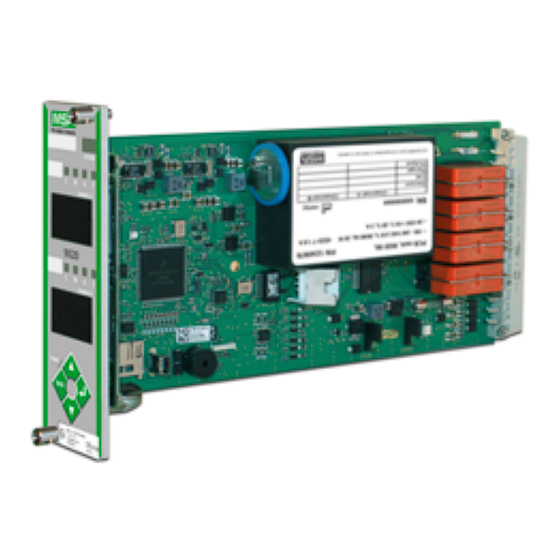
9010/9020 SIL Control Unit
Quick Start Guide
The quick start guide does not replace the operating manual. It is imperative that the operating manual be read
and observed when using the device. In particular, the safety instructions, as well as the information for use,
operation and maintenance of the device, must be carefully read and observed.
19 inch Rack Version – Mechanical installation
9010 rack board version
9020 rack board version
Rack for 5 modules (Panel cut out 246 x 133 mm)
19 inch rack – Module Backplane Terminal Connection
ALARM CHANNELS A and B
FAILURE CHANNELS A and B
WARNING CHANNELS A and B
CAUTION CHANNELS A AND B
HORN
ANALOG CHANNEL A+
SENSOR CONNECTION CHANNEL A
(see the connection diagram on the
TECHNICAL DATA SHEET of the sensor used)
not connected
10171753/01
WARNING
Rack for 2 modules (Panel cut out 124 x 133 mm)
Rack for 10 modules (Panel cut out 448 x 133 mm)
MAIN SUPPLY 100 - 230 VAC; 50 - 60 Hz
EARTH GROUND
BACK UP SUPPLY 24 VDC
HORN CUT OUT/ALARMS RESET (REMOTE)
ELECTRONIC EARTH (GROUND)
GND - EARTH (GROUND)
+ DATA
(120 Ohm termination resistor
RS 485
across DATA+ and DATA- terminal
- DATA
is required)
- ANALOG OUTPUT COMMON EARTH TO CHANNELS A AND B
+ ANALOG OUTPUT CHANNEL B (*)
SENSOR CONNECTION CHANNEL B (*)
(see the connection diagram on the
TECHNICAL DATA SHEET of the sensor used)
not connected
(*) NOT USABLE WITH MODEL 9010
Wall Mount version – Mechanical Installation
Wall mounted unit installation instruction:
(1)
Drill the holes as shown below for the four fixing screws.
(2)
Remove the housing lid carefully. Watch the display cable being connected to the
lid inside.
(3)
Fix the unit to the wall, by appropriate screws (M5 screws or 5 mm SPAX).
(4)
Close the lid with existing screws.
Wall mount, 9010 SIL
Wall mount, 9020 SIL
Wall Mount version – Terminal Connection
BACK UP SUPPLY
24 VDC
HORN CUT OUT/ALARMS RESET (REMOTE)
ELECTRONIC EARTH (GROUND)
RS 485
(120 Ohm termination resistor
across DATA+ and DATA- terminal
is required)
When opening the control unit housing, there is a risk of high voltage danger from relay contacts and main
power supply. Only authorised persons should open the control unit when it is switched off and secured against
unintentional switch-on. Before opening the housing, it must be confirmed that power is off for all poles.
MAIN SUPPLY
100 - 230 VAC; 50 - 60 Hz
ALARM
CHANNELS A AND B
FAILURE
CHANNELS A AND B
WARNING
CHANNELS A AND B
CAUTION CHANNELS A AND B
HORN
ANALOG OUTPUTS +CHANNEL A (CHA),
+CHANNEL B (CHB), COMMON EARTH (COM)
SENSOR CONNECTION - CHANNEL A (M6) and CHANNEL B (M3)
(SEE THE SENSORS CONNECTION DATA SHEETS)
CHANNEL B NOT USED WITH MODEL 9010
S-TERMINAL IS NOT CONNECTED
WARNING
www.MSAsafety.com
Schlüsselstrasse 12
8645 Rapperswil-Jona
Switzerland
Advertisement

Related Manuals for MSA 9010


Summary of Contents for MSA 9010
- Page 1 (SEE THE SENSORS CONNECTION DATA SHEETS) - DATA is required) HORN CHANNEL B NOT USED WITH MODEL 9010 - ANALOG OUTPUT COMMON EARTH TO CHANNELS A AND B S-TERMINAL IS NOT CONNECTED ANALOG CHANNEL A+ + ANALOG OUTPUT CHANNEL B (*)
- Page 2 Access Code 52* Input and Output Setup • Press ESC key to skip the Access Code 53* Default settings startup procedure Access Code 223 Password setup *Access Code 123 is required Refer to the manual for detailed Access Code functions description. NOTE: Please contact your local MSA representative if you have a problem with the unit setup or testing. www.MSAsafety.com Schlüsselstrasse 12 8645 Rapperswil-Jona Switzerland...
Need help?
Do you have a question about the 9010 and is the answer not in the manual?
Questions and answers