
Related Manuals for MSA SMC 5100-28-IT


Summary of Contents for MSA SMC 5100-28-IT
- Page 1 Operating Manual SMC 5100-28-IT Infrared Combustible Gas Sensor Module Document No./Revision: T12013/J4 Print Spec: 10000005389 (F) MSAsafety.com...
- Page 2 The warranties made by MSA with respect to the product are voided if the product is not installed and used in accordance with the instructions in this manual. Please protect yourself and your employees by following the instructions.
-
Page 3: Table Of Contents
4.2.1 Analog 4-20 mA Operation 4.2.2 Modbus Operation Using RS-485 Connection 4.2.3 Sentry Operation Using Sentry Connection 4.2.4 General Enclosure Installation Transmitter and Sensor Installation Module Address Switch Operation Introduction Data Entry Keypad Main Menu SMC 5100-28-IT IR Gas Sensor... - Page 4 7.6.6 Display Shows “M” – Not Calibrated 7.6.7 Display Shows “C” – Calibration Mode 7.6.8 Display Shows “S” – Sentry Connection 7.6.9 Diagnostic LEDs 7.6.10 Error Messages Specifications Parts List Limited Warranty Remote Sensor Drawing Modbus Memory Map HART SMC 5100-28-IT IR Gas Sensor...
-
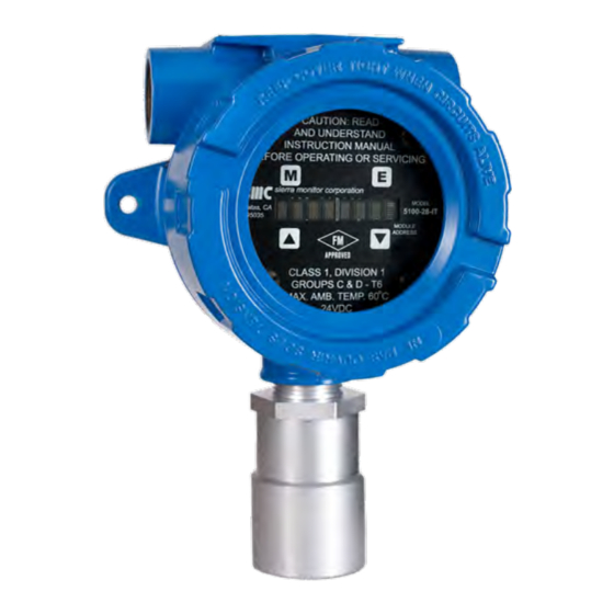
Page 5: Product Description
1 Product Description Product Description General The Model SMC 5100-28-IT Infrared Combustible Gas Sensor Module is a smart transmitter and member of the IT Series family and it offers a broad array of features including: • Integral alphanumeric LED display •... -
Page 6: Product Configuration
When the module is operated in conjunction with a Sentry controller, the alarm relay set-up (Section 5.3 Main Menu) should be set to “Sentry”, allowing the Sentry controller to manage alarm relay action rather than the SMC 5100-28-IT Gas Sensor Module. 1.4.2 Modbus Operation An RS-485 Modbus RTU serial interface allows direct connection to standard PLCs and DCSs. -
Page 7: Optional Integral Relays
1.5.1 Enclosure Standard on the SMC 5100-28-IT is a cast aluminum electrical housing with three ¾” FNPT conduit hubs. The SMC 5100- 28-IT-S has a 316 Stainless Steel enclosure. Both enclosure covers have a viewing window. The design of the enclosure allows 3-way mounting choices as shown below. - Page 8 1 Product Description Model 5100-28-IT-S1/S2 IR Combustible Gas Sensor – Stainless Steel Enclosure, Dimensions Model 5100-28-IT-A1/A2 IR Combustible Gas Sensor – Cast Aluminum Enclosure, Dimensions SMC 5100-28-IT IR Gas Sensor...
-
Page 9: Transmitter Electronics
Power Requirements The modules operate on 24 VDC power between 10 VDC and 30 VDC. Filtered, regulated DC power must be supplied from a separate source or from an approved Sentry or IT controller. SMC 5100-28-IT IR Gas Sensor... -
Page 10: Cautions & Warnings
The IR calibration frequency is 1 year. However, prudent gas detector maintenance practices normally suggest a simple recalibration following incidences of exposure to high levels of gas that would lead to alarm activation within any system utilizing the output of the gas sensor module. SMC 5100-28-IT IR Gas Sensor... -
Page 11: Quick Start
4 to 20 mA. The actual current is linear with the gas concentration and depends on the selected range. For instance, when the range of 0 to 100 %LEL has been selected, a current of 4 mA corresponds to 0 %LEL and a current of 20 mA corresponds to 100 %LEL. SMC 5100-28-IT IR Gas Sensor... -
Page 12: Installation
• Sensors should be pointed down and the conduit should include an inverse trap to reduce moisture (condensation) from accumulating in the electronics enclosure. • Remote calibration fitting (5360-00) should be used to facilitate calibration gas delivery. Run polyurethane tubing (1/4” O.D. x 1/8” I.D.) from fitting to an accessible location. SMC 5100-28-IT IR Gas Sensor... -
Page 13: Wiring
Sentry controller. Shield must be cut and dressed at the module end so that no part of it comes in contact with the conduit or ground. NOTE: Be sure to follow all local electric code and safety requirements when installing the SMC 5100-28-IT Gas Sensor Module. -
Page 14: General
NOTE: The drain wire of shielded cable must NOT be used as one of the conductors. Installation and wiring must be in accordance with the National Electrical Code. Temperature rating of cable wire must be at least 75°C. If cable runs through higher temperature environments, it must be specified for that environment. SMC 5100-28-IT IR Gas Sensor... -
Page 15: Enclosure Installation
3. For hazardous locations an Explosion poof seal fitting must be installed within 18" of the detector. NOTE: When enclosure earth grounding is required for the installation a grounding lug is located in the base of the enclosure. Install the earth ground under the green ground screw. SMC 5100-28-IT IR Gas Sensor... -
Page 16: Transmitter And Sensor Installation
RS 485 shield (Isolated GND) RS 485 RS 485 (+) (A) RS 485 (-) (B) RS 485 shield (Isolated GND) VDC Power Sentry Signal or Communication VDC Ground VDC Power Sentry Signal or Communication VDC Ground SMC 5100-28-IT IR Gas Sensor... - Page 17 ** Trouble relay is a fail-safe so it is energized for normal operation, functions are labeled for normal operation. NOTE: The starting delay period normally takes approximately 3 minutes but under some circumstances can take longer. For optimum performance, it is recommended that a calibration be performed after 24 hours of operation. SMC 5100-28-IT IR Gas Sensor...
-
Page 18: Module Address Switch
NOTE: Use selector switch to pick Sentry PSG addresses 1 through 8 only. If using Modbus output sensor addresses 1-15 are available. Position 0 allows the Modbus Address to be set by software menu, in the range 16-254. SMC 5100-28-IT IR Gas Sensor... - Page 19 4 Installation Interface Board Connectors RS-485 – Termination, BIAS Jumper SMC 5100-28-IT IR Gas Sensor...
- Page 20 4 Installation mA Circuit Types SMC 5100-28-IT IR Gas Sensor...
- Page 21 4 Installation 4-20 mA Circuit Type Connections for SMC 5100-28-IT SMC 5100-28-IT IR Gas Sensor...
- Page 22 4 Installation Wiring Connections for Modbus and Sentry Interface SMC 5100-28-IT TO SENTRY SMC 5100-28-IT TO MODBUS DEVICE SMC 5100-28-IT IR Gas Sensor...
- Page 23 4 Installation Wiring Connections for Remote Alarm Reset SMC 5100-28-IT Remote Alarm Reset (Unsupervised) (dry contact only unpowered) SMC 5100-28-IT IR Gas Sensor...
-
Page 24: Operation
Each switch functions as if it is a manually activated panel key. The keys are located under the faceplate above and below the LED display and are labeled M , E , ▲ and ▼ as shown below. SMC 5100-28-IT IR Gas Sensor... -
Page 25: Main Menu
HXXX %LEL High Alarm (Alarm) HIGH Measures gas, concentration exceeds 100% of Full Scale CXXX %LEL Calibration Mode Acknowledged Function NOTE: If display shows “Start” instead of “Starting”, the module must be calibrated before using it. SMC 5100-28-IT IR Gas Sensor... -
Page 26: Setup
◦ User defined value • RS-485 – Use the [▲] or [▼] keys to select Address or Baud rate menu and press [E]. Note that the SMC 5100-28-IT has a rotary switch on the faceplate and it is used to select addresses 1-15. When connected to Sentry the user can select 1-8 and when using Modbus RS-485 the user can select addresses 1-15. - Page 27 Baud S.P. Function - RS-485 Baud Rate Adjust Enter *38400 Press [E] to select or ▲ or ▼ to select another NOTE: The Key is the same as the function. Mode=M, Enter=E, Up=▲, and Down=▼. SMC 5100-28-IT IR Gas Sensor...
-
Page 28: Maintenance Sub-Menu
5 Operation Maintenance Sub-Menu The maintenance menu enables the operator to view sensor and software versions. MSA Safety technical support has access to other values as needed. The maintenance menu operation is described in the table below. Function Display Description... - Page 29 Displays Detector signal in Volts. Clears all internal non-volatile memories and restores factory defaults. The gas ClearMem detector module will reboot and power up in uncalibrated state. Run Time Displays the time gas detector module has been on power. SMC 5100-28-IT IR Gas Sensor...
-
Page 30: Calibration
300 cc/min Until Stable (minimum 3 minutes) NOTE: Following calibration, the IR module counts down for 300 seconds. During this time the module is updating its internal memory and it is very important that its power not be interrupted. SMC 5100-28-IT IR Gas Sensor... -
Page 31: Calibration Sub-Menu
Operation: No calibration gas applied, or sensor did not respond correctly WAIT-300 Operation: Five minute time out before sensor is returned to service Mode (Any) Operation: Hold magnet over Mode Switch for ten seconds to abort calibration Sub C Banner: Calibration Aborted --0%LEL- Default Display SMC 5100-28-IT IR Gas Sensor... -
Page 32: Service
3. Remove all wires from bond, marking them carefully so they can be correctly replaced. 4. Unplug the sensor connector from the transmitter. 5. Reverse the preceding steps to install the new transmitter. 6. Restore power and allow a minimum of 30 minutes for stabilization before re-calibration. SMC 5100-28-IT IR Gas Sensor... -
Page 33: Sensor Replacement
• Hot AC and relay connections have safety covers installed. 7.5.2 Cabling Installation • All splices are soldered or via terminal block. • Cabling is away from sources of electrical noise or RFI where possible. SMC 5100-28-IT IR Gas Sensor... -
Page 34: Sensor Module Installation
3. Plug the sensor back into the transmitter board carefully and ensure a secure fit. 4. Check all other connections. 5. Power up the unit. 7.6.4 Module Shows “***Calibration Required***” Calibrate the module. 7.6.5 Display Shows “H” or “L” This means the local high or low alarm is active. SMC 5100-28-IT IR Gas Sensor... -
Page 35: Display Shows "M" - Not Calibrated
Sensor clipping FAIL004 HDW Fail Detector clipping FAIL005 HDW Fail Reference clipping Push <D> Push <D> Burn-in Std Dev failure ERR: 200 TEST TBL Forced Trouble / Trouble EEP ERR MEM FAIL Memory CRC error SMC 5100-28-IT IR Gas Sensor... -
Page 36: Specifications
Normally open digital input Power Power Consumption 3 watts Input Voltage 24 VDC nominal: 10-30 VDC Input Current 200mA @24 VDC Operating Range Ambient Temperature Range -40° to 167°F (-40° to 75°C) Relative Humidity 0-99% (Non-condensing) SMC 5100-28-IT IR Gas Sensor... - Page 37 Modbus Baud 38400 (Adjustable 2400 – 38400) Parity None Stop Bit Data Bits Flow Control None Memory Map See Section 12 Modbus Memory Map Warranty Limited Warranty 2 years Specifications subject to change without notice SMC 5100-28-IT IR Gas Sensor...
-
Page 38: Parts List
Transmitter SPL21806-R Transmitter with Relays SPL21806-H Transmitter with HART SPL21825 Interface Board without Relay SPL21829 Interface Board with Relay SPL21876 Interface board with HART 22078 SS Magnetic Wand 22121 AL Magnetic Wand 45236 Ferrite Choke SMC 5100-28-IT IR Gas Sensor... -
Page 39: Limited Warranty
Limited Warranty MSA Safety warrants its products to be free from defects in workmanship or material under normal use and service for two years after date of shipment. MSA Safety will repair or replace without charge any equipment found to be defective during the warranty period. -
Page 40: Remote Sensor Drawing
The remote sensor assembly is meant to be supported by rigid conduit. Calibrate post installation. Typical wire connections at all terminations: Color Position Color Position Black Brown White Blue Orange Green Yellow + Drain Wire SMC 5100-28-IT IR Gas Sensor... -
Page 41: Modbus Memory Map
12 Modbus Memory Map Modbus Memory Map SMC 5100-28-IT IR Gas Sensor... -
Page 42: Hart
13 HART HART SMC 5100-28-IT IR Gas Sensor... - Page 43 13 HART SMC 5100-28-IT IR Gas Sensor...
- Page 44 A response code of 0 indicates SUCCESS. This applies to all commands. As per HART specification, all command responses will have a response code and status byte, plus any command specific data bytes as indicated in the following tables. SMC 5100-28-IT IR Gas Sensor...
- Page 45 Request Data Bytes: Byte Format Description 1=Enter 2=Down Unsigned-8 4=Up 8=Menu Command Specific Response Data Bytes: Byte Format Description Unsigned-8 Response Code Unsigned-8 Device Status Unsigned-8 Returns same value of the key / value that was passed SMC 5100-28-IT IR Gas Sensor...
- Page 46 Request Data Bytes: Byte Format Description Unsigned-16 Index to select parameter as per table above Response Data Bytes: Byte Format Description Unsigned-8 Response Code Unsigned-8 Device Status Unsigned-16 Index of selected parameter Float Value of parameter SMC 5100-28-IT IR Gas Sensor...
- Page 47 Set the action/mode of the Warning Relay. Request Data Bytes: Byte Format Description 0=Latching Unsigned-8 1=Sentry 2=Non-Latching (default) Response Data Bytes: Byte Format Description Unsigned-8 Response Code Unsigned-8 Device Status Unsigned-8 Returns new value of Warning Relay Action Variable SMC 5100-28-IT IR Gas Sensor...
- Page 48 Command 138: Apply ZERO Gas This command will signal the module to accept the present sensor output to as the ZERO gas condition. Request Data Bytes: None Response Data Bytes: Byte Format Description Unsigned-8 Response Code Unsigned-8 Device Status SMC 5100-28-IT IR Gas Sensor...
- Page 49 Unsigned-16 Index to select register with 40001 offset removed Response Data Bytes: Byte Format Description Unsigned-8 Response Code Unsigned-8 Device Status Unsigned-8 Index to select register with 40000 offset removed Float Value of Modbus register SMC 5100-28-IT IR Gas Sensor...
- Page 50 Command 146: Set Trouble Mode Output Current Request Data Bytes: Byte Format Description Unsigned-16 Current output required to indicate Trouble, in micro-amperes Command Specific Response Data Bytes: Byte Format Description Unsigned-16 Returns new Trouble current value SMC 5100-28-IT IR Gas Sensor...
- Page 51 Byte Format Description Unsigned-8 Index to select appropriate timer as per table above Response Data Bytes: Byte Format Description Unsigned-8 Response Code Unsigned-8 Device Status Unsigned-8 Index of selected timer Unsigned-32 Value of selected timer SMC 5100-28-IT IR Gas Sensor...
- Page 52 Float Float Value to be written to Modbus register Response Data Bytes: Byte Format Description Unsigned-8 Response Code Unsigned-8 Device Status Unsigned-8 Index of select register with 40000 offset removed Float New value of register SMC 5100-28-IT IR Gas Sensor...
Need help?
Do you have a question about the SMC 5100-28-IT and is the answer not in the manual?
Questions and answers