
Subscribe to Our Youtube Channel
Related Manuals for Kikusui PLZ-4W Series


Summary of Contents for Kikusui PLZ-4W Series
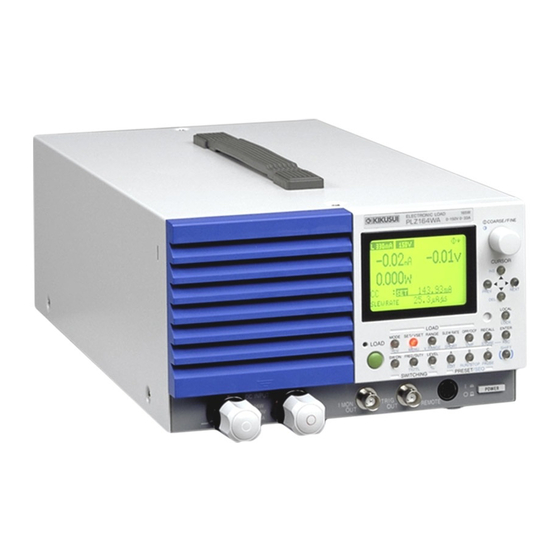
- Page 1 Part No. IB020912 Sep. 2010 USERS MANUAL ELECTRONIC LOAD PLZ-4W Series PLZ 164 W PLZ 164 WA PLZ 334 W PLZ 664 WA PLZ 1004 W...
- Page 2 Operation Manual Setup Guide The setup guide is intended for first-time users of the PLZ-4W series. It gives an overview of the PLZ- 4W series, connecting procedures, safety precautions, etc. Please read through and understand this guide before operating the product.
- Page 3 Safety Symbols For the safe use and safe maintenance of this product, the following symbols are used throughout this manual and on the product. Under- stand the meanings of the symbols and observe the instructions they indicate (the choice of symbols used depends on the products). Indicates that a high voltage (over 1000 V) is used here.
-
Page 4: Safety Precautions
Safety Precautions The following safety precautions must be observed to avoid fire haz- ard, electrical shock, accidents, and other failures. Keep them in mind and make sure that all of them are observed properly. Users • This product must be used only by qualified personnel who understand the con- tents of this operation manual. - Page 5 • To maintain performance and safe operation of the product, it is recommended that periodic maintenance, checking, cleaning, and calibration be performed. Service • Internal service is to be done by Kikusui service engineers. If the product must be adjusted or repaired, contact Kikusui distributor/agent. PLZ-4W...
-
Page 6: Table Of Contents
- - - - - - - - - - - - - - - - - - - - - - - - - - - - - - - - - - - - - - 1-2 PLZ-4W Series Lineup - - - - - - - - - - - - - - - - - - - - - - - - - - - - - - - - - - - 1-3... - Page 7 Types of Protection Functions - - - - - - - - - - - - - - - - - - - - - - - - - - - - - - 5-6 Setting the Protection Function - - - - - - - - - - - - - - - - - - - - - - - - - - - - - 5-8 Operation Modes - - - - - - - - - - - - - - - - - - - - - - - - - - - - - - - - - - - - - - - 5-9 CC Mode - - - - - - - - - - - - - - - - - - - - - - - - - - - - - - - - - - - - - - - - - - - 5-10 CR Mode - - - - - - - - - - - - - - - - - - - - - - - - - - - - - - - - - - - - - - - - - - - 5-13...
- Page 8 6.10.1 Parallel Operation Using the Same Model - - - - - - - - - - - - - - - - 6-62 6.10.2 Parallel Operation Using Load Boosters - - - - - - - - - - - - - - - - - 6-65 6.10.3 Alarms during Parallel Operation - - - - - - - - - - - - - - - - - - - - - - 6-66 6.10.4 Response Speed during Parallel Operation - - - - - - - - - - - - - - - - 6-66 6.10.5 Slew Rate during Parallel Operation - - - - - - - - - - - - - - - - - - - - 6-66...
- Page 9 A.2.6 Operation of the CR+CV Mode - - - - - - - - - - - - - - - - - - - - - - A-12 Operating Area of Each Model - - - - - - - - - - - - - - - - - - - - - - - - - - - - A-15 A.3.1 Operating Area of the PLZ164W - - - - - - - - - - - - - - - - - - - - - A-15 A.3.2 Operating Area of the PLZ334W - - - - - - - - - - - - - - - - - - - - - - A-16 A.3.3 Operating Area of the PLZ1004W - - - - - - - - - - - - - - - - - - - - - A-17...
- Page 10 VIII Contents PLZ-4W...
-
Page 11: Chapter 1 General Information
Chapter 1 General Information This chapter gives an overview and introduces the features of the PLZ-4W Series Electronic Loads. PLZ-4W General Information 1-1... -
Page 12: About This Manual
For the procedure of confirming the ROM version, see section 2.7, “Checking the ROM Version.” Product Overview The PLZ-4W Series Electronic Load is a multifunctional system designed to offer the highest levels of reliability and safety. The electonic load contains a stable and high-performance current control circuit that enables high-speed load simulations. -
Page 13: Plz-4W Series Lineup
1. Electronic load (PLZ-4W or PLZ-4WA) 2. Load booster (PLZ-4WB) Two types of the PLZ-4W Series are available depending on the input operating voltage. 1. Operating range of 1.5 V to 150 V. (PLZ-4W and PLZ-4WB) 2. Operating range of 0 V to 150 V. (PLZ-4WA) ■... -
Page 14: Features
Features In addition to the high-performance constant current, constant resistance, and con- stant power modes, the PLZ-4W Series Electronic Load offers wide variety of other features. ■ High-speed slew rate of 16 A/μs (PLZ1004W) The rise and fall slew rate of the current when switching at 2 % to 100 % (20 % to 100 % in M range) of the rated current in constant current mode is 16 A/μs... - Page 15 The sequence pattern can be edited easily using the large LCD. ■ Useful function for battery discharge tests The PLZ-4W can measure the time from load on to load off. When combined with the under voltage protection (UVP) function, the time from when the battery discharge is started until the battery voltage falls to the cutoff volt- age can be measured (time measurement).
-
Page 16: Overview Of Controls
Overview of Controls This section describes the controls on the electronic load and combined systems. Operation using the control panel The PLZ-4W employs a large LCD. Measured values of voltage, current, and power at the load input terminal are indicated at all times. The values are indicated using larger characters than other sections to improve the visibility. - Page 17 Support for large capacity To achieve large capacity at low cost, the PLZ1004W comes with a load booster (PLZ2004WB). Using a single PLZ1004W as a master unit, up to four load boosters can be con- nected in parallel (9 kW, 1800 A maximum). In parallel operation without using load boosters, up to five electonic loads of the same type including the master unit can be connected in parallel (5 kW, 1000 A maximum).
-
Page 18: Options
Options Control flat cables Control cable used to connect between the master unit and the slave unit (load booster) and between slave units. The following two types of cables are available. Model Code Length Application the master unit and the slave Connect between PC01-PLZ-4W 84540... - Page 19 KRB3-TOS EIA standard Rack mount bracket PLZ664WA (Fig. 1-5) PLZ1004W Milli rack KRB150-TOS JIS standard For details, contact your Kikusui agent or distributor. KRA3 KRA150 Unit: mm (inch) Fig. 1-4 Rack mount frame KRB150-TOS KRB3-TOS Unit: mm (inch) Fig. 1-5...
- Page 20 1-10 General Information PLZ-4W...
-
Page 21: Chapter 2 Installation And Preparation
Chapter 2 Installation and Preparation This chapter describes the procedures of unpacking and preparation before using the PLZ-4W. PLZ-4W Installation and Preparation 2-1... -
Page 22: Checking The Package Contents
When you receive the product, check that all accessories are included and that the product and accessories have not been damaged during transportation. If any of the accessories are damaged or missing, contact your Kikusui agent or dis- tributor. NOTE •... -
Page 23: Precautions Concerning Installation Location
fire. However, operation in such environments may be possible through alteration. If you wish to use the unit in such environments, consult your Kikusui agent or distributor. ■ Do not place the unit in a dusty location. Accumulation of dust can lead to electric shock or fire. -
Page 24: Precautions When Moving The Unit
■ Do not place objects on top of the unit. Placing objects on top of the unit can cause failures (especially heavy objects). ■ Do not place the unit on an inclined surface or location sub- ject to vibrations. The unit may fall or tip over causing damages and injuries. ■... -
Page 25: Connecting The Power Cord
Check that the POWER switch is turned off. Connect the power cord to the AC INPUT connector on the rear panel. Use a power cord specified by Kikusui or one that has been selected by a qual- ified engineer. Insert the power plug to the outlet. -
Page 26: Grounding (Earth)
Grounding (Earth) WARNING • Electric shock may occur, if proper grounding is not furnished. • This product is designed as a Class I equipment (equipment furnished with electric shock protection through protective grounding in addition to the basic insulation). Be sure to connect the protective ground terminal to an appropriate earth ground. -
Page 27: Turning On The Power
Turning on The Power Overview of the procedure Carry out this procedure without connecting anything to the DC INPUT (load input terminal). Turn on the POWER switch and then operate the LOAD key. At the end, turn off the POWER switch. ”... - Page 28 If one of the following conditions applies to your case, carry out the corresponding procedure. If the condition does not change even after taking the countermeasure indicated below, contact Kikusui distributor/agent. Nothing is displayed. Check the power cord connection and power cycle the unit.
-
Page 29: Checking The Rom Version
Adjusting the display contrast While pressing the SHIFT key, use the rotary knob to adjust the con- trast. The result is saved. Checking the ROM Version Firmware Version ROM Version Fig. 2-6 Model Information screen (PLZ164W) Press the MENU (SHIFT+SET/VSET) key. The menu screen is displayed. -
Page 30: Load Wiring
Refer to Table 2-1 and select thick wires as much as possible. Table2-1 Nominal cross-sectional area of wires and allowable currents Nominal Cross- (Reference Cross- Allowable Current(*) Kikusui-Recom- Sectional Area Sectional Area) mended Current (Ta = 30 °C) (2.08) (3.31) - Page 31 Load wire inductance The load wiring has an inductance (L). When the current (I) varies in short time period, it generates a large voltage at both ends of the wiring cable. This voltage applies to all of the load input terminals of the PLZ-4W when the impedance of the EUT is relatively small.
- Page 32 Fig. 2-9 to alleviate oscillation. In this case, use the capacitor within its allowable ripple current. Keep the wire short 100 cm or less Equipment PLZ-4W Series under test Electronic Load – – Twist Example: R=10 Ω, C=100 μF...
- Page 33 • If the polarity is reversed, overcurrent may damage the EUT and PLZ-4W. Be sure to match the polarities between the load input terminal and the equipment under test. Equipment PLZ-4W Series ≤ DC150 V under test Electronic Load –...
-
Page 34: Connection To The Load Input Terminal On The Rear Panel
2.8.2 Connection to the Load Input Terminal on the Rear Panel Using the terminal cover The load input terminal cover that comes with the package is used by passing through the load wire. If the wire that you are using is thick and cannot be passed through the cover sleeve (where the wire is passed through), cut and adjust the size of the sleeve to match the thickness of the wire. - Page 35 Connection procedure of the load input terminal on the rear panel WARNING • Do not touch the load input terminal while the PLZ-4W is turned ON, as it may lead to electric shock. In addition, be sure to use the load input terminal cover. •...
- Page 36 Move the cover until the edge touches the panel, and pinch the section indicated by the arrow to raise the side surface. With the side surface of the cover raised, insert the lock plate pin into the hole. Top view Check that the left and right lock plate pins are securely inserted in the cover holes.
-
Page 37: Connection To The Load Input Terminal On The Front Panel
2.8.3 Connection to the Load Input Terminal on the Front Panel The load input terminal on the front panel can be used to easily connect the equip- ment under test and the PLZ-4W. WARNING • Do not touch the load input terminal while the PLZ-4W is turned ON, as it may lead to electric shock. - Page 38 2-18 Installation and Preparation PLZ-4W...
-
Page 39: Chapter 3 For First Time Users
Chapter 3 For First Time Users This chapter describes for first time users, the operation modes of the PLZ-4W and matters that users should be familiar with in operating the PLZ-4W. PLZ-4W For First Time Users 3-1... -
Page 40: What Is An Electronic Load
What Is an Electronic Load When measuring the characteristics of the power supply in designing a power sup- ply, a load that is applied to the power supply is required. An electronic load refers to a device that uses semiconductors (transistors) in place of a variable resistor to act as a load. -
Page 41: Basic Flow Of Operation
Basic Flow of Operation This section runs through the precautions concerning installation and preparation, the use of the operation panel, and functions that are convenient for performing experiments and tests. • For details on the precautions concerning installation and preparation, see chap- ter 2, “Installation and Preparation.”... - Page 42 Warming up the PLZ-4W To perform stable measurements, allow the PLZ-4W to warm up for at least 30 min- utes before starting tests. While the PLZ-4W is warming up, check the operation of the PLZ-4W and the connection of the equipment under test. Voltage drop in the load wire If the load wire is long, a voltage drop occurs due to the resistance of the cable.
- Page 43 For details on maintenance, see chapter 8, “Maintenance and Calibration.” • If the PLZ-4W requires repairs or readjustment, do not open the outer cover by yourself. Contact your Kikusui agent. • When transporting the PLZ-4W, remove the power cord and cables, and use the original packing materials.
-
Page 44: Operating Area Of The Plz-4W
Operating area of the PLZ-4W As shown in Fig. 3-3, the PLZ-4W can be used within the area enclosed by the con- stant voltage line according to the rated voltage (L1), the constant power line according to the rated power (L2), the constant current line according to the rated current (L3), and the constant voltage line according to the minimum operating voltage (L4) (operating area where specifications are guaranteed). -
Page 45: Basic Operation Modes
(V1). Current is constant even when the voltage Constant-voltage changes power supply PLZ-4W Series Current [A] Electronic Load CC setting value Fig. 3-4 Equivalent circuit of the constant current load and operation ■ Transition of the operating point We will consider the case when checking the load characteristics of the constant- voltage power supply of Fig. - Page 46 Operating area Constant power line OPP trip point (OPP setting) Logarithmic Input current [A] scale Fig. 3-5 Transition of the operating point in CC mode (OPP trip point) Fig. 3-5: Operation on segment AB If the voltage of the constant-voltage power supply is set to V1 and the input current (load current) of the PLZ-4W is increased, the operating point moves along segment When point B is reached, overpower protection (OPP) trips.
-
Page 47: Let's Use Cc Mode
3.4.2 Let's Use CC Mode This section describes the procedure of setting the operation mode to CC and turn- ing on the load. Below is the flow of the operating procedure. Please familiarize yourself with the keys used in this procedure. ■... - Page 48 Select CC mode. H 33A 150V 0.00 0.000 Press the MODE key to show the operation mode pop-up menu. 0.000 If CC is not highlighted, press the MODE key repetitively until CC is high- lighted. 0.000 0.01 mA/μs SLEWRATE When the pop-up menu closes, check that CC appears on the display. Select the current range.
-
Page 49: Chapter 4 Names And Functions Of Parts
Chapter 4 Names and Functions of Parts This chapter describes the names and functions of switches, connectors, and dis- plays on the front panel and rear panel. PLZ-4W Names and Functions of Parts 4-1... -
Page 50: Front Panel
Front Panel WARNING • Do not touch the load input terminal while the PLZ-4W is turned ON, as it may lead to electric shock. In addition, be sure to use the load input terminal cover. • The load input terminals on the front and rear panels are coupled inside the PLZ-4W. - Page 51 [1] DC INPUT (load input terminal on the front panel) The terminal on the front panel that can be used to easily connect the equipment under test and the PLZ-4W. The load input terminal is also available on the rear panel, and is connected in parallel with the load input terminal on the front panel.
-
Page 52: Rear Panel
Rear Panel WARNING • Do not touch the load input terminal while the PLZ-4W is turned ON, as it may lead to electric shock. In addition, be sure to use the load input terminal cover. • The load input terminals on the front and rear panels are coupled inside the PLZ-4W. - Page 53 [1] DC INPUT (load input terminal on the rear panel) Terminal used to connect the equipment under test to the PLZ-4W. It is connected in parallel with the load input terminal on the front panel. • For the connection procedure, see section 2.8.2, “Connection to the Load Input Terminal on the Rear Panel.”...
-
Page 54: Operation Panel
Operation Panel If you press a key while holding down the SHIFT key, the function indicated below the key is enabled. ELECTRONIC LOAD 165W PLZ164W 150V 0 COARSE/ FINE [2] Rotary knob CURSOR PREV NEXT LOCAL [3] CURSOR LOAD LOCK MODE SET VSET RANGE... - Page 55 INS/DEL/PREV/NEXT Operate the keys while holding down the SHIFT key to turn pages (PREV/NEXT) on the menu screen or insert (INS) or delete (DEL) steps of the sequence function. [4] LOCAL/LOCK key LOCAL Switches to panel control (local control) when the PLZ-4W is being controlled remotely.
- Page 56 Pressing this key while holding down the SHIFT key (SHIFT+MODE) adds con- stant voltage mode (+CV) to CC mode or CR mode. When in CC mode, this operation switches the mode to CC+CV; when in CR mode, this operation switches the mode to CR+CV. The current mode is indicated on the display.
- Page 57 [10] OPP/OCP/UVP key OPP/OCP Sets the voltage for tripping the overpower protection (OPP) or the current for trip- ping the overcurrent protection (OCP). This key illuminates when you can set the OPP or OCP. • For details, see section 5.4, “Setting the Protection Function.” Pressing this key while holding down the SHIFT key (SHIFT+OPP/OCP) enables you to set the voltage for tripping the undervoltage protection (UVP).
- Page 58 [13] LEVEL/% key LEVEL Sets the switching level in switching operation. This key illuminates when you can change the switching level. Pressing this key while holding down the SHIFT key (SHIFT+LEVEL) enables you to set the switching level in terms of a percentage (0.0 % to 100.0 %) of the current setting.
- Page 59 [15] ENTER/ABC key ENTER Confirms various types of values during menu setup. • Pressing the ENTER key when an alarm is activated resets the alarm. However, the alarm will be activated again if you do not correct the cause of the alarm. Pressing this key while holding down the SHIFT key (SHIFT+ENTER) saves the current settings to the ABC preset memories.
-
Page 60: Display
Display You can change the display contract by turning the rotary knob while holding down the SHIFT key. The contrast setting is backed up even when the power is turned off. [1] Range display [2] Status display [3] Measured value display [4] Operation status display H 33A 150V 0.00... -
Page 61: Chapter 5 Basic Operation
Chapter 5 Basic Operation This chapter describes the operating procedure of each operation mode and other basic functions. PLZ-4W Basic Operation 5-1... -
Page 62: Panel Control Basics
Panel Control Basics The PLZ-4W is controlled from the operation panel on the front panel. If you make an invalid selection or perform an invalid key operation, a beep is sounded to notify the error. In particular, please familiarize yourself with the use of the SHIFT key that changes the key function. -
Page 63: Turning On Or Off The Load
Turning On or Off the Load “Turning on the load” refers to the operation of supplying current to the PLZ-4W. “Turning off the load” refers to the operation of cutting off the current to the PLZ- 4W. The LOAD key is used to turn on or off the load. Please remember the expres- sion “turning on the load”... - Page 64 ■ Displaying the elapsed time after the load is turned on By default, the elapsed time after the load is turned on is not displayed. If you select “1. Setup” | “1. Function” from the menu and set the Count Time set- ting to on, the time from load on to load off can be displayed.
- Page 65 Even when you follow the procedure specified above, the alarm may occurs, in such case, it may be required to change the voltage setting of CV to prevent the alarm occurance. For details, contact your Kikusui agent or distributor. PLZ-4W...
-
Page 66: Types Of Protection Functions
Types of Protection Functions The protection function automatically turns off or limits the load when an input that can damage the internal circuit of the PLZ-4W appears and to protect the equipment under test. When a protection function trips, an alarm is activated. When an alarm is activated, the load is turned off (or limited), and the ALARM STATUS of the J1 connector on the rear panel (pin 16) turns on (open collector output by a photocoupler). - Page 67 Undervoltage protection (UVP) The protection trips when the voltage that is equal to or falls below the specified voltage. At this point, the load is turned off. The undervoltage protection can be dis- abled (OFF). • For a description of setting the undervoltage value, see section 5.4, “Setting the Protection Function.”...
-
Page 68: Setting The Protection Function
Setting the Protection Function You can set trip points for the OCP, OPP, and UVP. ■ Setting the OPP and OCP The OPP and the OCP activate an alarm and turn off the load or limit the power or current when overpower or overcurrent occurs. When LOAD OFF is specified, a pop-up window appears when an alarm is activated. -
Page 69: Operation Modes
Operation Modes The following four operation modes are available on the PLZ-4W. Furthermore, constant voltage mode (+CV) can be added to CC and CR modes. • Constant current mode (CC mode and CC+CV mode) • Constant resistance mode (CR mode and CR+CV mode) •... -
Page 70: Cc Mode
CC Mode In CC mode, you set the current [A]. You can also add +CV mode to CC mode. Overview of the procedure Select the operation mode, and set the current value. Turn on the load and change the current value. Finally, turn off the load to cut off the current. - Page 71 Select the voltage range. Press the VRANGE (SHIFT+RANGE) key. A voltage range pop-up menu appears. Each time you press the VRANGE key, the voltage range switches between 15 V and 150 V. When the desired range is highlighted, stop pressing the key. Set the current value.
- Page 72 Select the current range and voltage range. Press the RANGE key to select the current range. Press the VRANGE (SHIFT+RANGE) key to select the voltage range. Set the current and voltage values. Check that the display is in the basic setting entry condition (the characters “SET”...
-
Page 73: Cr Mode
CR Mode In CR mode, you set the conductance [S], an inverse of the resistance. The resis- tance calculated from the conductance is also displayed. • Conductance [S] = 1/resistance [Ω] You can also add +CV mode to CR mode. In CR+CV mode, only the conductance is displayed. - Page 74 Select the current and conductance range. Press the RANGE key. A current range pop-up menu appears. Each time you press the RANGE key while the menu is displayed, the range switches in the order L, M, and H. When the desired range is highlighted, stop pressing the key. Along with L, M, or H, the full scale value of the respective range is displayed.
- Page 75 ■ Operating procedure of CR+CV mode LOAD LOCK MODE SET / VSET RANGE SLEW RATE OPP / OCP RECALL ENTER LOAD + CV MENU VRANGE SHORT STORE SW ON FREQ / DUTY LEVEL SHIFT Th/TL EDIT RUN / STOP PAUSE SWITCHING PRESET SEQ Fig.
-
Page 76: Cv Mode
CV Mode In CV mode, you set the Voltage [V]. Overview of the procedure Select the operation mode, and set the voltage value. Turn on the load and change the voltage value. Finally, turn off the load to cut off the current. Preparation Main operation Unit behavior... - Page 77 Select the voltage range. Press the VRANGE (SHIFT+RANGE) key. A voltage range pop-up menu appears. Each time you press the VRANGE key, the voltage range switches between 15 V and 150 V. When the desired range is highlighted, stop pressing the key. Set the voltage value.
-
Page 78: Cp Mode
CP Mode In CP mode, you set the wattage (W). Overview of the procedure wattage Select the operation mode, and set the Turn on the load and change the wattage. Finally, turn off the load to cut off the current. Preparation Main operation Unit behavior... - Page 79 Select the voltage range. Press the VRANGE (SHIFT+RANGE) key. A voltage range pop-up menu appears. Each time you press the VRANGE key, the voltage range switches between 15 V and 150 V. When the desired range is highlighted, stop pressing the key. Set the wattage value.
-
Page 80: Soft Start
5.10 Soft start The PLZ-4W can be set to start up slowly of the input current of the PLZ-4W (soft start) in the constant current (CC) mode and the constant resistance (CR) mode when the applying voltage and the turning on the load at the same time, or when the voltage applied with 0 V input of the load input while the load is turned on. - Page 81 Select Function. Setu Press the CURSOR key several times until Function is highlighted on Function 2. Protect Action the menu. 3. Memor 4. Cut Off When highlighted, press the ENTER key. 5. Res onse PREV NEXT Select soft start time. Function Check that the cursor is blinking by Soft Start on the menu, and turn the rotary Soft Start...
-
Page 82: Lock Function
5.11 Lock Function The PLZ-4W can be locked to prevent erroneous operation such as inadvertently changing the settings or overwriting the memory or sequence. The functions that can be used and those that cannot be used when the lock function is enabled are indicated below. - Page 83 Select the menu setup. Press the MENU (SHIFT + SET/VSET) key. Menu 1. Setu The menu appears. Confi uration 3. Calibration Select Configuration 4. Model Info PREV NEXT Press the CURSOR key several times until Configuration is high- lighted on the menu. When highlighted, press the ENTER key. Confi uration Select Power On.
-
Page 84: Short Function
For a description of the J1 connector, see “J1 and J2 Connectors” in section 6.8, “External Control.” CAUTION • Be sure to use a dedicated driver circuit to drive the relay for high current. Equipment under test PLZ-4W Series Electronic Load Relay J1 connector on the rear panel –... -
Page 85: Menu Setup
5.13 Menu Setup The menu is used to change the operating conditions of the PLZ-4W and the default settings of functions. This section describes the operations on the menu and a list of menu items. The hierarchical structure of the menu is shown below. Setu Menu Function... - Page 86 • Operation of selecting menu items You can also select the menu item by turning the rotary knob. Turning the rotary knob to the right moves the highlight downward; turning it to the left moves the highlight upward. Then, select the next menu. Setu Function Press the...
- Page 87 Table5-2 Menu items Menu name 1 Menu name 2 Item name Values <*1> 1. Setup 1. Function Soft Start 1 ms, 2 ms, 5 ms, 10 ms, 20 ms, 50 ms, 100 ms, 200 ms Count Time (elapsed time display) OFF, ON 2.
-
Page 88: Initialization
5.14 Initialization The backup function of the PLZ-4W retains the current settings, menu settings, and memory contents (ABC preset memories and setup memory) even when the POWER switch is turned off. You can initialize the PLZ-4W settings to factory default by carrying out the following operation. •... -
Page 89: Response Speed
5.15 Response Speed The PLZ-4W operates by detecting the input current or voltage and feeding back those values. You can set the response speed of the negative feedback control. The response speed can be specified in CC mode (CC+CV mode) and CR mode (CR+CV mode). - Page 90 5-30 Basic Operation PLZ-4W...
-
Page 91: Chapter 6 Applied Operation
Chapter 6 Applied Operation This chapter describes functions such as ABC preset memories, switching function, and sequence function that are used in actual applications. PLZ-4W Applied Operation 6-1... -
Page 92: Abc Preset Memories
ABC preset memories Three separate sets of settings for each range of each operation mode can be saved to memories A, B, and C. Settings are saved or recalled after determining the opera- tion mode and range. Settings (A, B, and C) saved in the current operation mode at the current range can be recalled. -
Page 93: Saving To Abc Preset Memories
6.1.1 Saving to ABC preset memories Three separate sets of settings for each range of each operation mode can be saved to memories A, B, and C. The settings can be saved even when the load is turned on. Select the ABC preset memories. First, switch to the desired operation mode and set the range and value. - Page 94 Select Setup. Press the CURSOR key several times until Setup is highlighted on the menu. When highlighted, press the ENTER key. Select Memory. Press the CURSOR key several times until Memory is highlighted on the menu. When highlighted, press the ENTER key. Select the recall method of ABC preset memories.
- Page 95 • In CC, CR, CV, or CP mode (saves one setting) H 33A 150V Range setting 0.00 0.000 Recalls the setting (current, resistance, voltage, or power) that had been saved 0.000 to preset memory A, B, or C at the curre Setting operation mode and range setting.
-
Page 96: Setup Memory
Setup Memory The setup memory can store up to 100 sets (0 to 99) of the current conditions of the items shown below. You can attach a memo using up to 15 characters to each mem- ory set. The stored settings can be recalled as necessary. ■... -
Page 97: Saving To The Setup Memory
ELECTRONIC LOAD 165W PLZ164W 150V 0 COARSE / FINE CURSOR PREV NEXT LOCAL LOAD LOCK MODE SET / VSET RANGE SLEW RATE OPP / OCP RECALL ENTER LOAD + CV MENU VRANGE SHORT STORE SW ON FREQ / DUTY LEVEL SHIFT Th/TL EDIT... -
Page 98: Recalling The Setup Memory
Save the settings to the setup memory. Press the ENTER key. The STORE key illuminates. The settings described above are saved to the memory. If settings are already stored at the selected memory number, the settings are overwrit- ten. The STORE key remains illuminated while the saved settings are used. 6.2.2 Recalling the Setup Memory Check that the load is turned off. - Page 99 • In CC, CR, CV, or CP mode Recalls the operation mode, range setting, H 33A 150V Range setting one setting (current, resistance, voltage, 0.00 0.000 or power), and the contents of ABC preset memories saved at the operation mode 0.000 and range setting that are saved to the Setting...
-
Page 100: Switching Function
Switching Function Switching refers to the operation of executing two load current settings repetitively. The switching function operates in CC and CR modes. The switching function is suited to transient response characteristics test of regulated DC power supplies. You can perform various tests by setting the switching frequency, ON/OFF ratio of the switch (duty cycle), switching level, and switching time. - Page 101 Turn on the switching mode. Press the SW ON key. The SW ON key illuminates, and the switching mode is enabled. • Setting the switching function using frequency and duty cycle Select switching frequency and duty cycle. Press the FREQ/DUTY key. The FREQ/DUTY key illuminates.
-
Page 102: Setting The Slew Rate
Setting the Slew Rate The slew rate defines the slope for changing the current when the current is changed rapidly such as by using the switching function in CC and CR modes. On the PLZ- 4W, you set the amount of change in the current per unit time according to the cur- rent range. -
Page 103: Using The Elapsed Time Display And The Auto Load Off Timer
Using the Elapsed Time Display and the Auto Load Off Timer Two convenient functions are available for the discharge tests of batteries. • Measure the time from discharge start until the cutoff voltage is reached (time measurement). • Measure the closed circuit voltage after a specified time elapses from discharge start (voltage measurement). -
Page 104: Sequence Function
Sequence Function Sequence is a function that automatically executes instructions specified in advance one operation at a time. By specifying a sequence of operations (steps), various waveform simulations can be executed. The sequence that you create is saved by the backup function even when the power is turned off. -
Page 105: Overview Of The Normal Sequence
6.6.1 Overview of the Normal Sequence To create a sequence, you must understand the concept of “program” and “step.” Step 001 Program Step 002 Step 003 • • • Step 001 Maximum number of Program Step 002 programs is 10 Step 003 •... - Page 106 • Step In a single step, one execution condition can be specified. In other words, one oper- ation of the executed waveform corresponds to one step. In normal sequence mode, up to 256 steps can be shared among all programs (10 programs). Below are the settings of a step.
- Page 107 • TRIG (trigger output) TRIG sets the presence or absence of trigger output. When turned on, a trigger sig- nal is output from the TRIG OUT connector on the front panel at the same time as the step is executed. (Example) Set trigger output at step number n (TRIG ON) Step n...
-
Page 108: Sequence Editing
6.6.2 Sequence Editing The sequence edit screen is divided into the following four edit screens. When creat- ing a sequence, items are set on each edit screen. This section describes the setup items on each edit screen and the setup procedure. (1) Program operation Set the program number, memo, operation mode, range, and the number of Memo : Pro... - Page 109 NOTE • The program operation screen is divided into top and bottom halves. Pressing the key at the bottom line (Loop) of the top half of the screen moves the cursor to the bottom half of the screen. Pressing the key at the first line (Last Load) of the bottom half of the screen moves the cursor to the top half of the screen.
- Page 110 Table6-3 Setup items on each setup screen Edit screen Setup item Description Program number (1 to 10) Memo Memo (11 characters) Mode Operation mode (CC, CR, CV, or CP) Range Range setting (Current range - Voltage range) Number of program loops Loop (1 to 9999) 9999 is infinite loop Program operation...
-
Page 111: Sequence Example (Normal Sequence)
6.6.3 Sequence Example (Normal Sequence) Programs are created using the PLZ-4W operation panel. This section describes the procedure of entering the following example sequence from the operation panel. • Flow of the example sequence In this example, we will assume a sequence that executes 2 programs (program numbers 1 and 2) to simulate the waveform of Fig. - Page 112 Creating the program Here, we will create program 1 and then program 2. Programs can be created in any order. Therefore, you can create program 2 first and then program 1. Select sequence edit. Press the EDIT (SHIFT+A) key to display the program edit (SEQ) screen. ■...
- Page 113 Set the current setting after the end of the program. (Last Set :) Turn the rotary knob to set the current value. Last Load : OFF Last Set : 0.000 Since the load is turned off at the end of program 1, select 0 A. However, Chain : OFF because the sequence continues to program 2 in this example (step 9), this set-...
- Page 114 14. Set the execution time of step 1. SEQ EDIT h : m i n : s . m s On the initial screen, the time is 0:00:00.001. Press the key to move the cur- 0:00 : 00 . 001 002 0:00 : 00 .
- Page 115 22. Select the operation mode, range, and the number of program loops. Set the operation mode, range, and the number of program loops of program 2 Memo : Pro ram2 in the same fashion as steps 4 to 6. Mode : NCC e : 33A, 150V In program 2, set the operation mode to CC, the range to 33 A, 150 V Loop : 0002...
- Page 116 ■ Reediting and confirming the sequence The program that you create is saved by the backup function even when the power is turned off. To confirm or reedit programs you have created, select sequence edit again. Select sequence edit. Press the EDIT (SHIFT+A) key. Memo : Pro ram2 Mode : NCC...
-
Page 117: Overview Of The Fast Sequence
6.6.4 Overview of the Fast Sequence To create a sequence, you must understand the concept of “program” and “step.” Step 0001 Step 0002 Program 11 Step 0003 • • • Step 1024 Maximum number of steps is 1024 Fig. 6-16 Conceptual diagram of program and step NOTE •... - Page 118 A program is a collection of steps (execution unit). When program 11 is executed (RUN), steps are executed one by one in ascending order from step number 0001. The completion of the last step signifies the end of one program execution. •...
-
Page 119: Fast Sequence Editing
6.6.5 Fast Sequence Editing The sequence edit screen is divided into the following four edit screens. When creat- ing a sequence, items are set on each edit screen. This section describes the setup items on each edit screen and the setup procedure. (1) Program operation Set the program number (always set to 11), memo, operation mode, range, and : 11... - Page 120 Table6-4 Setup items on each setup screen Edit screen Setup item Description Program number (11) Memo Memo (11 characters) Mode Operation mode (CC or CR) Range Range setting (Current range - Voltage range) Number of program loops Loop (1 to 9999) 9999 is infinite loop Program operation Load condition after the end of the sequence Last Load...
-
Page 121: Sequence Example (Fast Sequence)
6.6.6 Sequence Example (Fast Sequence) Programs are created using the PLZ-4W operation panel. This section describes the procedure of entering the following example sequence from the operation panel. • Flow of the example sequence In this example, we will assume a sequence that executes a program to simulate the waveform of Fig. - Page 122 • No. Program number (11) • Memo Memo (PLZ164W) • Range Current range-voltage range (33A-15V) • Loop Number of program loops (3) • Last Load Load condition at the end (ON) • Last Set Current value at the end (1 A) •...
- Page 123 Set the number of program loops. Turn the rotary knob to show the number of program loops. : 11 Memo : Set 0003 to specify 3 loops. Mode : FCC e : 33A , 15V Loop : 0003 At the last line, move the CURSOR key to move to the next item.
- Page 124 The following three items are specified. Step number Current value Presence or absence of trigger output Press the key to select the item, and turn the rotary knob to set the value or symbol. 11. Set step 1. Press the key to select the step number.
- Page 125 ■ Monitoring the settings Select sequence edit. Press the EDIT (SHIFT+A) key to display the program edit screen. Press the ENTER key to move to the monitor screen. Set the magnification. 10.00 STEP:0014 Press the key to move the cursor to magnification, and turn the rotary knob to set the magnification.
-
Page 126: Executing, Pausing, Stopping The Sequence
6.6.7 Executing, Pausing, Stopping the Sequence ■ Executing the Sequence Check that the switching function and short function are turned off. Check that the SW ON key is turned off and that the short icon is not dis- played. Even if turned on, the switching function and short function are forc- ibly turned off when the sequence execution screen is entered. - Page 127 When sequences cannot be executed Sequences cannot be executed across different modes and ranges. You cannot execute a sequence if the mode or range of the chained program is different. Check the settings. If the load is turned on and the current mode and range settings do not match the settings of the sequence that you are trying to exe- cute, you cannot execute the sequence.
-
Page 128: Remote Sensing Function
0.5 or more. Use crimp terminals for M3 screws for the connection on the PLZ-4W end. Remote sensing terminal on the rear panel –S White Equipment PLZ-4W Series Twist under test Electronic Load – – Fig. 6-21 Remote sensing wiring... -
Page 129: External Control
External Control 6.8.1 Overview and Precaution of External Control The settings in each operation mode normally use the internal reference signal. In external control, this reference signal is supplied externally. The external signal is either voltage (voltage control) or resistance (resistance control). External control can control the settings from 0 % to 100 % of the selected range in the CC, CR, CP, or CV mode. -
Page 130: J1/J2 Connector
Precaution when operating under high-speed load simulations When operating under high-speed load simulations, do not connect the common ter- minal of the external device and the terminal of the EUT which connects to the neg- ative polarity of load input terminal of the PLZ-4W. Attach the ferrite core on the connecting wire between the external device and the PLZ-4W. - Page 131 WARNING • When the PLZ-4W is shipped from the factory, protection dummy plugs are attached to the J1 and J2 connectors. To prevent the possibility of electric shock, leave the dummy plug attached to the connectors when you are not using them. CAUTION •...
- Page 132 Table6-9 J1 connector pin arrangement Signal name Description EXT R/V CONT Can be used in CC, CR, CV, and CP modes 0 V to 10 V correspond to 0 % to 100 % of the rated current (CC mode), rated voltage (CV mode), or rated power (CP mode).
- Page 133 Table 6-10 J2 connector pin arrangement Signal name Description N.C. N.C. N.C. SUM I MON Connect to SUM I MON of the J1 connector. PRL OUT+ Used during master/slave operation. Connected to PRL IN+ of the J1 connector. PRL OUT- Used during master/slave operation.
-
Page 134: External Control Of Cc Mode
6.8.3 External Control of CC Mode The external control of CC mode can be carried out using external voltage or exter- nal resistance. The input current varies proportionally to the external voltage or external resistance. (1) External voltage control Applying an external voltage in the range of 0 V to 10 V to the PLZ-4W produces an input current that is proportional to the change. - Page 135 ■ Setup procedure for external voltage control This procedure is common to CC, CR, CP, and CV modes. Follow this procedure for modes other than CC mode. NOTE • Use external voltage of low noise and high stability. • Use twisted wires for the signal wires. This can prevent disturbance from noise. Check that the power is turned off.
- Page 136 ■ Accurately proportionating the external voltage variation and input current variation You can use the pre-set resistors OFS and FSC on the PLZ-4W rear panel to adjust the current offset value and maximum current value, respectively. The adjustment enables control that is accurately proportional to the external voltage. The adjust- ment is valid for the specified range.
- Page 137 (2) External resistance control Connecting an external resistance in the range of 0 Ω to 10 kΩ to the PLZ-4W pro- duces an input current that is proportional or inversely proportional to the change. Proportional control The input current corresponding to the external resistance of 0 Ω is 0 A; the input current corresponding to the external resistance of 10 kΩ...
- Page 138 ■ Setup procedure for external resistance control This procedure is common to CC, CR, CP, and CV modes. Follow this procedure for modes other than CC mode. NOTE • It is recommended that the external variable resistor connected to the PLZ-4W be a wire wound resistor, metal film resistor, or multirotational potentiometer that is resistant to temperature and aging.
- Page 139 NOTE • You can prevent the settings from being changed inadvertently during measure- ment by pressing the LOCK (SHIFT+LOCAL) key to enable the lock. ■ Accurately proportionating the external resistance variation and input current variation You can use the pre-set resistors OFS and FSC on the PLZ-4W rear panel to adjust the current offset value and maximum current value, respectively.
-
Page 140: External Control Of Cr Mode
6.8.4 External Control of CR Mode The external control of CR mode can be carried out using external voltage or exter- nal resistance. The resistance varies proportionally to the external voltage or exter- nal resistance. (1) External voltage control Applying an external voltage in the range of 0 V to 10 V to the PLZ-4W produces a resistance proportional to the change. - Page 141 (2) External resistance control Connecting an external resistance in the range of 0 Ω to 10 kΩ to the PLZ-4W pro- duces a resistance that is proportional or inversely proportional to the change. Proportional control The external voltage of 0 Ω and 10 kΩ correspond to the maximum and minimum resistances of the range, respectively.
-
Page 142: External Control Of Cp Mode
6.8.5 External Control of CP Mode The external control of CP mode can be carried out using external voltage or exter- nal resistance. The wattage varies in proportion to the external voltage or external resistance. (1) External voltage control Applying an external voltage in the range of 0 V to 10 V to the PLZ-4W produces a wattage proportional to the change. - Page 143 (2) External resistance control Connecting an external resistance in the range of 0 Ω to 10 kΩ to the PLZ-4W pro- duces a wattage that is proportional or inversely proportional to the change. Proportional control The wattage corresponding to the external resistance of 0 Ω is 0 W; the wattage cor- responding to the external resistance of 10 kΩ...
-
Page 144: External Control Of Cv Mode
6.8.6 External Control of CV Mode The external control of CV mode can be carried out using external voltage or exter- nal resistance. The voltage varies in proportion to the external voltage or external resistance. (1) External voltage control Applying an external voltage in the range of 0 V to 10 V to the PLZ-4W produces a voltage proportional to the change. - Page 145 (2) External resistance control Connecting an external resistance in the range of 0 Ω to 10 kΩ to the PLZ-4W pro- duces a voltage that is proportional or inversely proportional to the change. Proportional control The voltage corresponding to the external resistance of 0 Ω is 0 V; the voltage corre- sponding to the external resistance of 10 kΩ...
-
Page 146: External Control Of Load On And Load Off
6.8.7 External Control of Load On and Load Off The external control connector can be used to control the on/off of the load and monitor the on/off condition. External contact control To control the load on/off using an external contact, an external signal is applied across pins 7 and 12 of the J1 connector. -
Page 147: Trigger Signal Control
Status signal output To externally monitor the load on/off condition, the output signal across pins 13 and 17 of the J1 connector is monitored. Maximum applied voltage 30 V Maximum current 8 mA Photocoupler (P.C) Load on Load off Photocoupler Fig. -
Page 148: External Control Of The Current Range
6.8.9 External Control of the Current Range The current range can be controlled using an external control signal. In addition, the status signal output can be used to monitor the selected range. The voltage range cannot be controlled. Table 6-12 A list of control signals Control input Status output Current... -
Page 149: Alarm Signal Control
6.8.10 Alarm Signal Control An alarm can be activated using an external control signal. In addition, the status signal output can be used to monitor the alarm condition. Alarm signal input Connect the external signal across pins +5 V 10 and 12 of the J1 connector. An alarm Approx. -
Page 150: Monitor Signal Output
Monitor Signal Output Trigger signal output The trigger signal is used as a synchronization signal when monitoring the wave- form of the switching operation on an oscilloscope. It is also used to synchronize with the external equipment during sequence execution. The trigger signal is output from the TRIG OUT connector on the PLZ-4W front panel. - Page 151 Range H/L M I MON OUT connector (BNC) 0.1 V Monitor output Across pins 2 and 3 of the J1 connector 10 V Current Full scale of range (Total value of all units connected in parallel during parallel operation) Fig. 6-48 Current monitor output For parallel operation, the full scale of the current range is the total value of the units connected in parallel.
-
Page 152: Parallel Operation
6.10 Parallel operation The PLZ-4W Series Electronic Load allows parallel operation in which multiple electronic loads can be connected in parallel to increase the current capacity or power capacity. In parallel operation, one unit becomes a master unit in charge of all controls in parallel operation. - Page 153 – Master unit DC INPUT 1000W 150V 200A Equipment under test – Load wire – Slave unit 1 DC INPUT J1-J2 cable 1000W 150V 200A – Slave unit 2 DC INPUT 1000W 150V 200A Fig. 6-49 Parallel connection of two slave units Table 6-13 shows the relationship between the number of slave units and the capacity.
- Page 154 Parallel connection procedure Connect the master unit and slave units using optional flat cables. Connect to the equipment under test using load wires. For a description of the wiring procedure and wire diameter, see section 2.8, “Load Wiring.” CAUTION • Use a load wire with sufficient diameter for the current as well as non-flam- mable or flame-resistant cover.
-
Page 155: Parallel Operation Using Load Boosters
• Master unit Set as a master unit. Master/Slave First, turn the rotary knob to the right to select MASTER. Operation : MASTER Parallel : -- Booster : -- When slaves are connected, press the CURSOR key to move the cursor to the Parallel item. -
Page 156: Alarms During Parallel Operation
6.10.3 Alarms during Parallel Operation When an alarm occurs during parallel operation, an error message is displayed, and the load of all units is turned off. If an alarm occurs on a slave unit, “ALARM EXTERNAL” is displayed on the mas- ter unit. -
Page 157: Chapter 7 Remote Control
Chapter 7 Remote Control This chapter givess an overview of reemote control. For detail of the command, see the Communication Interface Manual. The commnunication Interface Manual is provided on the accompanying CD-ROM. PLZ-4W Remote Control 7-1... -
Page 158: Overview
Overview In addition to using the front panel controls, the PLZ-4W can be controlled remotely using the following interfaces. • RS232C interface • GPIB interface • USB interface The remote interface accepts two formats of commands: IEEE 488.2 common com- mands and SCPI commands. -
Page 159: Interface Setup
Interface Setup The factory default remote control interface setting is GPIB. 7.2.1 GPIB Control ■ GPIB connection Use a standard IEEE488 cable to connect the PLZ-4W to the PC. ■ GPIB configuration Check that the load is turned off. Check that the LOAD LED is turned off. If it is on, press the LOAD key to turn it off. -
Page 160: Rs232C Control
7.2.2 RS232C Control ■ RS232C connection Use a standard cross cable (null modem cable) to connect the PLZ-4W to the PC. The RS232C port on the PLZ-4W is a standard DB9P male connector. Table7-1 RS232C pins Pin No. Function Not used Receive (RX) Transmit (TX) Not used... - Page 161 Exit from the menu. Press the MENU (SHIFT+SET/VSET) key. The original screen displayed before entering menu setup appears. 10. Power cycle the PLZ-4W. The settings are confirmed. ■ Transmission/Reception via the RS232C Control the transmission/reception via the RS232C interface using flow control or by using acknowledge messages.
-
Page 162: Usb Control
7.2.3 USB Control To use the USB, download the KI-VISA software program from Kikusui website (http://www.kikusui.co.jp), and install the software in PC. The software program can only be used on a Windows environment. ■ USB connection Use a standard USB cable to connect the PLZ-4W to the PC. -
Page 163: Contents Of The Accompanying Cd-Rom
Contents of the accompanying CD-ROM Insert the accompanying CD-ROM in the drive. After a short time, the menu pro- gram window opens. If the menu program window does not open, browse the CD- ROM with Windows Explorer, and double-click index.html. The menu program will start. -
Page 164: Installing The Visa Library
• Agilent VISA by Agilent Technologies (Agilent IO Libraries M01.00 or later) • KI-VISA Ver. 3.0.0 or later Installing KI-VISA KI-VISA is Kikusui's original VISA library that supports VXIplug&play VISA Specifications. The newest version can be downloaded from Download service of Kikusui website (http://www.kikusui.co.jp/en/download/). - Page 165 Uncheck Protect my computer and data from unauthorized program activity, and click OK. Uncheck Proceed with the installation according to the instructions on the screen. PLZ-4W Remote Control 7-9...
-
Page 166: Installing The Software Application
7.3.2 Installing the Software Application Kikusui PLZ Application & Samples includes the following software. Table 7-3 Software VPanel Simple virtual panel Monitor And Log Measures Curr/Volt/Pow, generates logs Step Editor A program/Step editor Memory Copy A memory backup tool for Setup Memories Load the accompanying CD-ROM into the CD-ROM drive. -
Page 167: Chapter 8 Maintenance And Calibration
Chapter 8 Maintenance and Calibration This chapter describes how to maintain, inspect, and calibrate the PLZ-4W. PLZ-4W Maintenance and Calibration 8-1... -
Page 168: Maintenance
Maintenance Periodic maintenance and inspection are essential to maintain the initial perfor- mance of the PLZ-4W over an extended period. WARNING • Possible electric shock. May lead to death or injury. Be sure to turn off the POWER switch and remove the power cord plug or turn off the switch- board. -
Page 169: Inspecting The Power Cord
If the panel settings are different at the time the power is turned off and at the time the power is turned on again, the battery is already dead. To replace the battery, contact your Kikusui agent or distributor. PLZ-4W... -
Page 170: Confirming Status Of The Fuse
If the LED lights, the fuse may have blown off. In this case, contact your Kikusui distributor/agent for request of service. Check for the input voltage and the input current within the rated value. If the mea- sured value is out of rated range, the LED may lights on even the fuse does not blow off. -
Page 171: Calibration
Calibration The PLZ-4W is shipped from the factory after carrying out a strict calibration. However, to maintain the performance, periodic calibration is recommended. 8.3.1 Calibration Overview The calibrated items are current and voltage. The current is calibrated with respect to the current ranges (3 ranges: L, M, and H). The voltage is calibrated with respect to the voltage ranges (2 ranges: 15 V and 150 For each range, the offset and gain are calibrated. -
Page 172: Preparation
Current: 0.3 A *1:PLZ164W/PLZ164WA, *2:PLZ334W, *3:PLZ664W, *4:PLZ1004W Connect the cables as shown in Fig. 8-5. Select the shunt resistor according to the calibration item. Voltmeter (DVM) Regulated DC PLZ-4W Series Shunt resistor power supply Electronic Load – – –S Voltmeter (DVM) Fig. -
Page 173: Calibration Procedure
8.3.3 Calibration Procedure Entering the calibration screen and selecting Calibration Press the MENU (SHIFT+SET/VSET) key. The menu screen is displayed. Use the CURSOR key to select 3. Calibration. 3. Calibration is highlighted. Press the ENTER key. The Calibration screen appears. Calibration 2. - Page 174 CC mode calibration (calibration number 1, 2, and 3) Carry out calibration on the low range items first according to steps A to D. Then, carry out calibrations for Mid range and High range. Table 8-2 Overview of the procedure Calibration item Percentage with Internal reference...
- Page 175 CC(Low) Displays the current Offset Adjustment calibration value (hexadecimal) first. DAC REF : 0x0001 Cursor MON : 0x0001 PREV NEXT Indicates hexadecimal. Fig. 8-7 CC (Low) Offset Adjustment screen Press the CURSOR key to select DAC REF, and turn the rotary knob.
- Page 176 Step D: Calibration of the gain of the internal reference voltage for protection function setting 12. Press the ENTER key. The gain calibration (CC (Low) Limit Gain Adjust) screen appears. 13. Press the CURSOR key to select DAC LIM, and turn the rotary knob.
- Page 177 CV mode calibration (calibration number 4 and 5) Carry out calibration on the 15-V range items first according to steps E to H. Then, carry out calibration on the 150-V range items. The shunt resistor is not used, but you can leave it connected. Table 8-4 Overview of the procedure Calibration item...
- Page 178 Press the CURSOR key to select DAC REF, and turn the rotary knob. Monitor the input voltage on an external voltmeter, and set the input voltage within ±0.05 % of the value corresponding to 10 % of the range full scale. MON is automatically set as the offset of the measured value.
- Page 179 ■ High range calibration 13. Return to number 1 of step E and calibrate the High range (calibration number “5. CV 150V”) by carrying out a similar procedure. Set the volt- age of the power supply to 155 V or greater. Step 12 completes the CV mode calibration.
-
Page 180: Malfunctions And Causes
If you find an item that corresponds to your case, follow the remedy for the item. If the remedy does not solve the problem or if your case does not match any of the items, contact your Kikusui agent. Symptom 1: Nothing appears on the display when the POWER switch is turned on. - Page 181 Symptom 4: Input current is unstable or oscillates. Check Item Possible Cause Remedy Location and Status of the Object Check Result Use the PLZ-4W in the input Low supply voltage supply voltage range. Is rated voltage applied for the input power supply (AC)? Immediately stop the use of the Malfunction instrument and request repairs.
- Page 182 Symptom 7: The transmission/reception does not work when you communicate using the program previously used. Check Item Remedy Location and Status of the Object Check Result There is a case that your program targeted at PLZ-4W ROM version 1.17 or earlier may not work correctly with ROM version 1.18 or later.
-
Page 183: Chapter 9 Specifications
Chapter 9 Specifications This chapter lists the electrical and mechanical specifications of the PLZ-4W. PLZ-4W Specifications 9-1... -
Page 184: Electrical Specifications
Electrical Specifications Unless specified otherwise, the specifications are for the following settings and conditions. • The warm-up time is 30 minutes (with current flowing). • After warm-up is complete, the PLZ-4W must be calibrated correctly according to the procedures given in the operation manual in a 23 °C±5 °C environment. •... - Page 185 CR mode Model PLZ164W PLZ334W PLZ1004W PLZ164WA PLZ664WA Range 22 S 44 S 133.332 S 22 S 88 S Operating range – 400 μS – 800 μS – 2.4 mS – 400 μS – 1.6 mS (45.455 mΩ (22.727 mΩ (7.5 mΩ...
- Page 186 CP mode Model PLZ164W PLZ334W PLZ1004W PLZ164WA PLZ664WA Operating range Range 16.5 W – 165 W 33 W – 330 W 100 W – 1 000 W 16.5 W – 165 W 66 W – 660 W 1.65 W – 16.5 W 3.3 W –...
- Page 187 Switching mode Model PLZ164W PLZ334W PLZ1004W PLZ164WA PLZ664WA Operation mode CC and CR Duty cycle setting 5 % – 95 % , 0.1 % step Selectable frequency range 1 Hz – 20 kHz Frequency 1 Hz – 10 Hz 0.1 Hz resolution 10 Hz –...
- Page 188 Remote sensing Model PLZ164W PLZ334W PLZ1004W PLZ164WA PLZ664WA Voltage that can be 2 V for a single line compensated Protection function Model PLZ164W PLZ334W PLZ1004W PLZ164WA PLZ664WA Overvoltage protection (OVP) Turns off the load at 110 % of the rated voltage Overcurrent protection (OCP) 0.03 A –...
- Page 189 Common specifications Analog external control (J1 connector) Load on/off control input Turn on the load with low (or high) TTL level signal Load on status output On when the load is on (open collector output by a photocoupler) Range switch input Switch ranges L, M, and H using a 2-bit signal Range status output Outputs range L, M, or H using 2-bit signal (open collector output by a photocoupler)
-
Page 190: General Specifications
EMC Directive 2004/108/EC EN 61326-1 Under following condition. The maximum length of all connecting cables and wires to the PLZ-4W series are less than 3 m. Complies with the requirements of the following directive and standard. *3,*4 Safety Low Voltage Directive 2006/95/EC... -
Page 191: Dimensions
Dimensions 4-φ5(1.97) 4-φ30(11.81) 4-M3 screw holes (Mounting holes (Feet diameter) for feet) (Max. depth 5mm(1.97inch)) 70(27.56) 275(108.27) (21.65) MAX470(185.04) 214.5(84.45) MAX30(11.81) 400(157.48) UNIT: mm (inch) Fig.9-1 Outline drawing (PLZ164W, PLZ164WA, and PLZ334W) 4-φ5(1.97) 4-φ30 4-M3 screw holes (Mounting holes for feet) (Feet diameter) (Max. depth 5mm(1.97inch)) 275(108.27) (28.74) (20.47) MAX470(185.04) MAX455(179.13) MAX30(11.81) 400(157.48) 429.5(169.09) 23(9.06) 367(144.49) (3.94) 8-M4 screw holes Unit :... - Page 192 9-10 Specifications PLZ-4W...
-
Page 193: Appendix
Appendix The appendices cover the operating area of the PLZ-4W, the basic operation modes and sequence program creation table. Operating Area of the PLZ-4W As shown in Fig. A-1, the PLZ-4W can be used within the area enclosed by the con- stant voltage line according to the rated voltage (L1), the constant power line accord- ing to the rated power (L2), the constant current line according to the rated current (L3), and the constant voltage line according to the minimum operating voltage (L4) -
Page 194: Basic Operation Modes
(V1). Current is constant even when the voltage Constant-voltage changes power supply PLZ-4W Series Current [A] Electronic Load CC setting value Fig. A-2 Equivalent circuit of the constant current load and operation ■ Transition of the operating point: Overpower protection (OPP) We will consider the case when checking the load characteristics of the constant- voltage power supply of Fig. - Page 195 Operating area Constant power line OPP trip point (OPP setting) Logarithmic Input current [A] scale Fig. A-3 Transition of the operating point in CC mode (OPP trip point) Fig. A-3: Operation on segment AB If the voltage of the constant-voltage power supply is set to V1 and the input current (load current) of the PLZ-4W is increased, the operating point moves along segment When point B is reached, overpower protection (OPP) trips.
-
Page 196: Operation Of The Cr Mode
Resistance (V/I) is constant even when the voltage and current vary Constant voltage power supply PLZ-4W Series Electronic Load Current I Fig. A-4 Equivalent circuit of the constant resistance load and opera- tion ■ Transition of the operating point: Overpower protection (OPP) We will consider the case when checking the load characteristics of the constant- voltage power supply of Fig. - Page 197 If protection action is set to LIMIT, the PLZ-4W sinks current as a constant power load at point B. Even if you attempt to increase the input current by decreasing the resistance, the current is limited at point B. If you decrease the input current by increasing the resistance, the OPP is cleared.
-
Page 198: Operation Of The Cp Mode
PLZ-4W P = V × I is kept constant. In Fig. A-7, P = V2 × I2 = V3 × I3. Power (current × voltage) is constant even when the current and voltage vary Constant voltage power supply PLZ-4W Series Electronic Load Rated maximum Current I current value Fig. A-7 Equivalent circuit of the CP mode and operation ■... - Page 199 Fig. A-8: Operation on segment AB If the voltage of the constant-voltage power supply is set to V1 and the power of the PLZ-4W is increased (P ), the operating point moves along segment AB →P →P →A →B). When point B is reached, overcurrent protection (OCP) trips. At this point, two types of operation are available on the PLZ-4W depending on the protection action setting of the OCP.
-
Page 200: Operation Of The Cv Mode
The PLZ-4W may operate unstably if R1 is low. Voltage is constant even when the current varies Constant voltage power supply PLZ-4W Series Electronic Load Current I Fig. A-9 Equivalent circuit of the CV mode and operation ■ Transition of the operating point: Overpower protection (OPP) We will consider the case when checking the load characteristics of the constant- voltage power supply of Fig. - Page 201 When point N is reached, overpower protection (OPP) trips. At this point, two types of oper- ation are available on the PLZ-4W depending on the protection action setting of the OPP. If Protect Action is set to LOAD OFF, the load is turned off. If protection action is set to LIMIT, the PLZ-4W sinks current as a constant power load at point N.
-
Page 202: Operation Of The Cc+Cv Mode
Battery CV operation value Voltage is constant even when the current varies PLZ-4W Series Electronic Load Current I CC setting value Fig. A-12 Equivalent circuit of the CC+CV mode and operation ■ Transition of the operating point: Overpower protection (OPP) We will consider the case when checking the discharge characteristics of a battery of Fig. - Page 203 We denote the voltage of the battery as V . In CC mode, if the current is increased ) to increase the input current (load current), the operating point →I →I moves along segment MN (M →M →N). When the overpower protection (OPP) setting is P , the OPP trips when point N is reached.
-
Page 204: Operation Of The Cr+Cv Mode
CV operation value Voltage is constant even when the current varies PLZ-4W Series Electronic Load Current I Fig. A-14 Equivalent circuit of the CR+CV mode and operation ■ Transition of the operating point: Overpower protection (OPP) We will consider the case when checking the discharge characteristics of a battery of Fig. - Page 205 We assume that the overcurrent protection (OCP) setting I is greater than cur- rent I at point N and denote the voltage of the battery as V . In CR mode, if the resistance is decreased (R ) to increase the input current (load cur- →R →R rent), the operating point moves along segment MN (M...
- Page 206 We assume that the overcurrent protection (OCP) setting I is less than the cur- rent produced by the tripping of the overpower protection (OPP) and denote the voltage of the battery as V . In CR mode, if the resistance is decreased ) to increase the input current (load current), the operating point →R →R...
-
Page 207: Operating Area Of Each Model
Operating Area of Each Model A.3.1 Operating Area of the PLZ164W Operating area where specifications are guaranteed Actual operating area PLZ164W Operating area where (1.5 V input specifications are guaranteed type) H range Actual operating area Low voltage area Input current [A] Input current [A] Operating area where specifications are guaranteed... -
Page 208: Operating Area Of The Plz334W
A.3.2 Operating Area of the PLZ334W Operating area where specifications are guaranteed Actual operating area PLZ334W Operating area where (1.5 V input specifications are guaranteed type) H range Actual operating area Low voltage area Input current [A] Input current [A] Operating area where specifications are guaranteed PLZ334W... -
Page 209: Operating Area Of The Plz1004W
A.3.3 Operating Area of the PLZ1004W Operating area where specifications are guaranteed Actual operating area PLZ1004W (1.5 V input Operating area where type) specifications are guaranteed H range Actual operating area Low voltage area Input current [A] Input current [A] Operating area where specifications are guaranteed Actual operating area... -
Page 210: Operating Area Of The Plz164Wa
A.3.4 Operating Area of the PLZ164WA PLZ164WA (0 V input type) Operating area where H range specifications are guaranteed Input current [A] PLZ164WA (0 V input type) Operating area where specifications are guaranteed M range 0.11 0.01 Input current [A] PLZ164WA (0 V input type) Operating area where... -
Page 211: Operating Area Of The Plz664Wa
A.3.5 Operating Area of the PLZ664WA PLZ664WA (0 V input type) Operating area where H range specifications are guaranteed Input current [A] PLZ664WA (0 V input type) Operating area where M range specifications are guaranteed 13.2 Input current [A] PLZ664WA (0 V input type) Operating area where L range... -
Page 212: Sequence Program Creation Table
Sequence Program Creation Table For normal sequence Program name: Date: Program number (1 to 10) Memo (Up to 11 characters) Operation mode CC, CR, CV, CP Range (A) -- Current (A) -- Voltage (V) Loop (1 to 9999) Last Load (OFF/ON) OFF, ON Last Set Chain (OFF, 1 to 10) - Page 213 Entry example Program name: Example sequence of chapter 6: PLZ164W Date: Program number (1 to 10) Memo Program1 (Up to 11 characters) Operation mode Range 33 (A) -- 150 (V) Current (A) -- Voltage (V) Loop (1 to 9999) 0001 Last Load (OFF/ON) Last Set Chain (OFF, 1 to 10)
- Page 214 A-22 Appendix PLZ-4W...
-
Page 215: Index I
Index Symbols closed circuit voltage 6-13 coarse adjustment 5-2 % key 4-10 COARSE/FINE 4-6 +CV key 4-7 communication function 9-7 +CV mode 5-10 5-13 conductance 5-13 5-14 5-15 +S end 6-38 configuration 5-27 constant current and constant voltage mode 3-7 A-10 Numerics constant current mode 3-7... - Page 216 J1/J2 connector 4-5 6-40 J2 connector pin arrangement 6-43 Earth 2-6 EDIT key 4-11 elapsed time display 4-12 key icon 5-22 electronic load, definition of 3-2 ENTER key 4-11 EXT CONT 4-5 external 5-27 large capacity, support for 1-7 external communication interface 1-6 last load 6-15 external control 6-39 last set 6-15...
- Page 217 model info 5-27 power supply, connection to 2-5 multi display 4-12 POWER switch 4-3 preset memory, recalling of 6-3 preset memory, saving to 6-3 product version 1-2 No. 6-15 program 6-15 normal sequence 6-14 program 11 6-27 program number 6-15 program, creation of 6-22 6-32 OCP 5-6...
- Page 218 SET/VSET key 4-8 voltage drop in the load wire 3-4 settings, monitoring of 6-35 voltage measurement 6-13 setup 5-27 voltage range 3-10 setup display 4-12 VRANGE key 4-8 setup memory 6-6 SHIFT key 3-5 short function 5-24 warm-up 3-4 short icon 5-24 weight 9-8 SHORT key 4-8 slew rate 6-12...
Need help?
Do you have a question about the PLZ-4W Series and is the answer not in the manual?
Questions and answers