
Related Manuals for Panasonic EX-Z Series


Summary of Contents for Panasonic EX-Z Series
- Page 1 Ultra-minute Photoelectric Sensor EX-Z Series USER’S MANUAL WUME-EXZ-1 Phone: 800.894.0412 - Fax: 888.723.4773 - Web: www.clrwtr.com - Email: info@clrwtr.com...
-
Page 2: Table Of Contents
Contens 1. Cautions ··························································································3 2. Part Description ················································································4 3. Mounting ·························································································5 3-1 Mounting of sensor ················································································· 5 3-2 Installation interval ················································································· 7 4. I/O Circuit Diagram ············································································9 5. Stability Indicator ············································································· 10 6. Beam Alignment ·············································································· 11 7. Option ··························································································· 12 7-1 Sensor mounting bracket ········································································12 8. -
Page 3: Cautions
Cautions WARNING ● Never use this product as a sensing device for personnel protection. ● When using sensing devices for personnel protection, use products that meet laws and standards, such as OSHA, ANSI or IEC etc., for personnel protection applicable in each region or country. -
Page 4: Part Description
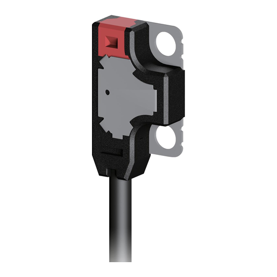
Part Description Thru-beam emitter side sensing type EX-Z11□, EX-Z12□, EX-Z13□ Beam emitting part Thru-beam receiver side sensing type EX-Z11□, EX-Z12□, EX-Z13□ Operation indicator (Orange) Stability indicator (Green) Lights up when the sensing output Lights up under the stable light condition is ON. -
Page 5: Mounting
Mounting 3-1 Mounting of sensor ● The tightening torque should be 0.2N·m or less. ● M2 screw and nut, spring washer, and flat washer are accessory of this product. When tapping in mounting section (Unit: mm) <Side sensing type> <Front sensing type> Sensing Sensing direction... - Page 6 When using sensor mounting bracket (optional) L-shaped mounting bracket Mounting bracket for front sensing type MS-EXZ-2 MS-EXZ-1 Mounting bracket for side sensing type Mounting spacer for front sensing type MS-EXZ-3 MS-EXZ-4 Phone: 800.894.0412 - Fax: 888.723.4773 - Web: www.clrwtr.com - Email: info@clrwtr.com...
-
Page 7: Installation Interval
3-2 Installation interval ● Interference prevention function is not incorporated in this product. In case mounting two sets of this product close together, please mount it as drawing below indicates. (Typical example) ● Find out the operating point ℓ1 on the parallel deviation diagram for the sensing distance L1. - Page 8 EX-Z12□, EX-Z12F□ <Parallel deviation diagram (typical)> In case using at sensing distance (L2) 200mm, the operation point (ℓ2) is approx. 30.5mm according (L2) to the diagram at left. The installation interval is (ℓ2) Approx. 30.5mm X 2 = approx. 61mm Thus, install the product to approx.
-
Page 9: I/O Circuit Diagram
I/O Circuit Diagram NPN output type and PNP output type common: Thru-beam type emitter EX-Z1□ (Brown) + V 12 to 24V DC ‒ ±10% (Blue) 0V Internal circuit Users’ circuit NPN output type: Thru-beam type receiver EX-Z1□ (Brown) + V Load (Black) Output 12 to 24V DC... -
Page 10: Stability Indicator
Stability Indicator ● The stability indicator (green) lights up when the incident light intensity has sufficient margin to the operation level. When the beam is received at a level where the stability indicator lights up, stable sens- ing is possible in both the "Light" state operation and the "Dark" state operation without being affected by changes in temperature, voltage, etc. -
Page 11: Beam Alignment
Beam Alignment Place the emitter and the receiver face to face along a Sensing object straight line. Move the emitter in the up, down, left and right directions, in order to determine the range of the light received condition with the help of the operation indicator (orange), and place it almost at the center. -
Page 12: Sensor Mounting Bracket
Option 7-1 Sensor mounting bracket Product name Model No. Description Mounting bracket common to side sensing type and front sensing type (2 sets required) Material: Stainless steel (SUS304) MS-EXZ-1 M2 (length 4mm) screw: 2 screws, M2 (length 8mm) screw: 2 screws are attached Sensor mounting Mounting bracket for front sensing type (2 sets required) bracket... -
Page 13: Specifications
Specifications 8-1 Side sensing type Sensing distance 50mm type Sensing distance 200mm type Sensing distance 500mm type Type Light-ON Dark-ON Light-ON Dark-ON Light-ON Dark-ON EX-Z12A EX-Z12B EX-Z13A EX-Z13B NPN output EX-Z11A EX-Z11B Model No. EX-Z12A-P EX-Z12B-P EX-Z13A-P EX-Z13B-P (note 2) PNP output EX-Z11A-P EX-Z11B-P... -
Page 14: Front Sensing Type
8-2 Front sensing type Sensing distance 50mm type Sensing distance 200mm type Sensing distance 500mm type Type Light-ON Dark-ON Light-ON Dark-ON Light-ON Dark-ON EX-Z12FA EX-Z12FB EX-Z13FA EX-Z13FB NPN output EX-Z11FA EX-Z11FB Model No. (Note 2) PNP output EX-Z11FA-P EX-Z11FB-P EX-Z12FA-P EX-Z12FB-P EX-Z13FA-P EX-Z13FB-P Sensing distance 50mm 200mm... -
Page 15: Dimensions
Dimensions Thru-beam type side sensing type EX-Z11□, EX-Z12□, EX-Z13□ (Unit: mm) 2-ø2.2 2-ø2.2 4.25 4.25 ø2 cable 2m long ø2 cable, 2m [Cable diameter: ø0.6 (Note 1)] [Cable diameter: ø0.6 (Note 1)] <Emitter> <Receiver> Note: The cable diameter of inflection resistant cable type is ø0.7mm. Thru-beam type front sensing type EX-Z11F□, EX-Z12F□, EX-Z13F□... - Page 16 Sensor mounting bracket MS-EXZ-1 (Unit: mm) 10.5 4-M2 X 0.4 thru-hole threads 1.75 4.75 Sensor mounting bracket MS-EXZ-2 18.7 (Unit: mm) 6.25 1.75 4-M2 X 0.4 thru-hole threads Sensor mounting bracket MS-EXZ-3 17.7 (Unit: mm) 2-M2 X 0.4 thru-hole threads Phone: 800.894.0412 - Fax: 888.723.4773 - Web: www.clrwtr.com - Email: info@clrwtr.com...
- Page 17 Spacer for mounting at the back MS-EXZ-4 (Unit: mm) 2-ø2.2 Phone: 800.894.0412 - Fax: 888.723.4773 - Web: www.clrwtr.com - Email: info@clrwtr.com...
Need help?
Do you have a question about the EX-Z Series and is the answer not in the manual?
Questions and answers