
Related Manuals for Panasonic EX-31A


Summary of Contents for Panasonic EX-31A
- Page 1 Amplifier Built-in Type Threaded Miniature Photoelectric Sensor EX-30 Series USER’S MANUAL WUME-EX30-3 2013.03 panasonic.net/id/pidsx/global...
-
Page 2: Table Of Contents
Contents 1. Cautions ··························································································3 2. Part Description ················································································4 3. Mounting ·························································································5 3-1 Mounting the sensor ··············································································· 5 3-2 Installation interval ················································································· 6 4. I/O Circuit Diagram ············································································8 5. Adjustment ·······················································································9 5-1 Beam alignment (Thru-beam type EX-31□ / EX-33□) ····································· 9 5-2 Sensitivity adjustment (Thru-beam type EX-33□, Diffuse reflective type EX-32□) ··10 6. -
Page 3: Cautions
Cautions WARNING ● Never use this product as a sensing device for personnel protection. ● In case of using devices for personnel protection, use products which meet laws and standards, such as OSHA, ANSI or IEC etc., for personnel protection applicable in each region or country. -
Page 4: Part Description
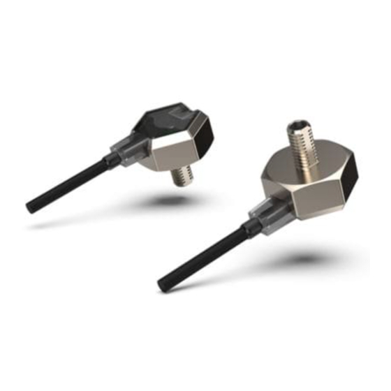
Part Description Thru-beam type EX-31□ Operation indicator Stability indicator (Orange) (Green) Output ON: lights up Stable light re- Beam axis ceived condition or stable dark condition: light up <Emitter / Receiver> <Receiver> <Emitter> Thru-beam type EX-33□ Operation indicator Stability indicator (Orange) (Green) Output ON: Lights up... -
Page 5: Mounting
Mounting 3-1 Mounting the sensor ● Mount the sensor on a mounting plate 3mm or less thick and use the enclosed nut and toothed lock washer for mounting. ● When the nut is tightened, hold the the sensor with hand or a spanner etc. and the tight- ening torque should be 0.6N·m or less. -
Page 6: Installation Interval
3-2 Installation interval ● This product does not incorporate auto interference prevention function. In case aligning 2 of this sensors closely, follow diagrams below. (typical) ● Find out the operating point ℓ1 on the parallel deviation diagram for the setting distance L. Separate sensors by 2 ×... - Page 7 Thru-beam type EX-31□ / EX-33□ EX-31□: Approx. 100.6mm or more EX-33□: Approx. 120.4mm or more EX-31□: Approx. 100.6mm or more EX-33□ Approx.120.4mm or more EX-31□: 500mm EX-33□: 800mm Diffuse reflective type EX-32□ Approx. 18.2mm or more Approx. 18.2mm or more 50mm...
-
Page 8: I/O Circuit Diagram
I/O Circuit Diagram NPN output type and PNP output type: Emitter of thru-beam type EX-31□ / EX-33□ Color code (Brown) +V 12 to 24V DC ±10% (Blue) 0V Internal circuit Users’ circuit NPN output type: Receiver of Thru-beam type EX-31□ / EX-33□, Diffuse reflective type EX-32□ Color code (Brown) +V Load... -
Page 9: Adjustment
Adjustment 5-1 Beam alignment (Thru-beam type EX-31□ / EX-33□) Thru-beam type EX-31□ 1. Place the emitter and the receiver face to face along Sensing object a straight line, move the emitter in the up, down, left and right directions, in order to determine the range of the light received condition with the help of the Operation indicator... -
Page 10: Sensitivity Adjustment (Thru-Beam Type Ex-33□, Diffuse Reflective Type
5-2 Sensitivity adjustment (Thru-beam type EX-33□, Diffuse reflective type EX-32□) Thru-beam type EX-33□ ● When using EX-33□, turn the sensitivity adjuster fully clockwise to the MAX. position. However, if the beam penetrates a sensing object, adjust the sensitivity as follows. Step Sensitivity 1. - Page 11 Diffuse reflective type EX-32□ Step Sensitivity 1. Turn the sensitivity adjuster fully counterclockwise to the adjuster minimum sensitivity position 2. In the light received condition, turn the sensitivity adjust- Operation indicator er slowly clockwise and confirm the point A where the (Orange) sensor enters the “Light”...
-
Page 12: Stability Indicator
Stability Indicator ● The stability indicator (green) lights up when the incident light intensity has sufficient margin with respect to the operation level. Incident light intensity level is such that the stability indicator light up, stable sensing can be done without the light received operation and the light interrupted operation being af- fected by a change in ambient temperature or supply voltage. -
Page 13: Beam Slit Mask (Thru-Beam Type
Option 7-1 Beam Slit Mask (Thru-beam type EX-31□ / EX-33□) ● Apply the optional slit mask (OS-EX30-1) when detecting small objects or for increasing the accuracy of sensing position. However, the sensing range is reduced when the slit mask is mounted. Model No. -
Page 14: Specifications
Notes: 1) The model No. with suffix “P” shown on the label affixed to the thru-beam type sensor is emitter. “D” shown on the label is receiver. (e.g.) Emitter of EX-31A: EX-31P, Receiver of EX-31A: EX-31AD 5m cable length type is also available for NPN output type (excluding EX-33□) When ordering this type, suffix “-C5”... -
Page 15: Dimensions
Dimensions Thru-beam type EX-31□ (Emitter and Receiver) Opposing faces 7, (Unit: mm) thickness 2.4 Tooth lock washer ø8.5 15.6 M4 × 0.7 ø2.5 cable 2m Thru-beam type EX-33□ (Emitter and Receiver) Opposing faces 7, (Unit: mm) thickness 2.4 Tooth lock washer ø8.5 15.6 0.75 ø7.2... - Page 16 Diffuse reflective type EX-32□ Opposing faces 10, (Unit: mm) thickness 2 Tooth lock washer ø11 15.6 0.75 ø7.2 M6 × 0.75 ø2.5 cable 2m Slit mask OS-EX30-1 (optional) (Unit: mm) (5.3) <Spacer> (8.02) Internal thread part ø8 ø4.3 M4 × 0.7, ø1 3.8 deep Material: Brass (Nickel plated)
- Page 17 (MEMO)
- Page 18 Please contact ..http://panasonic.net/id/pidsx/global Overseas Sales Division (Head Office) 2431-1 Ushiyama-cho, Kasugai-shi, Aichi, 486-0901, Japan Phone: +81-568-33-7861 FAX: +81-568-33-8591 About our sale network, please visit our website. PRINTED IN JAPAN © Panasonic Industrial Devices SUNX Co., Ltd. 2013 WUME-EX30-3...
Need help?
Do you have a question about the EX-31A and is the answer not in the manual?
Questions and answers