Panasonic EQ-500 Series Instruction Manual
Photoelectric sensor, adjustable range reflective
Hide thumbs
Also See for EQ-500 Series:
- Specification sheet (10 pages) ,
- Instruction manual (2 pages) ,
- Manual (10 pages)
Advertisement
Quick Links
INSTRUCTION
MANUAL
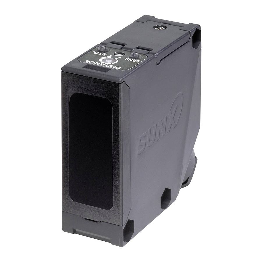
Photoelectric Sensor
Adjustable Range Reflective
EQ-500 Series
MJE-EQ500 No.0066-68V
1
SPECIFICATIONS
Type
Model No.
EQ-501
Item
With timer
EQ-501T
Adjustable range (Note 1) (Note 2)
0.2 to 2.5m
Sensing
range
(Setting
0.1 to 2.5m
distance maximum) (Note 2)
Hysteresis (Note 2)
24 to 240V AC
Supply voltage
Ripple P-P 10% or less
Power / Current
AC: 4VA or less (With timer: 5VA or less)
consumption
DC: 3W or less (With timer: 4W or less)
Relay contact 1a
Switching capacity: 250V AC 3A (resistive load)
Output
Electrical life: 100,000 or more operations
Mechanical life: 50,000,000 or more operations
Output operation
Short-circuit protection
Response time
20ms or less (Depends on the timer setting period for EQ-50 T)
Sensing mode
Timer function
Automatic interference
prevention function
Protection
Ambient temperature
Ambient humidity
Emitting element
Receiving element
Material
Connection method
Cable
Cable length
Weight
Accessory
Notes: 1)
The adjustable range stands for the maximum sensing range which can be set with the adjuster.
2)
The adjustable range, the sensing range and the hysteresis are specified for white non-glossy paper (200 200mm) as the object.
3)
When the sensors are mounted closely, use them in the interference prevented area, as shown below.
3
2
1
L mm
Interference
or more
prevented area
0
20
40
60
Mounting interval L (mm)
Note that the detection may be unstable depending on the mounting conditions or the sensing object. In the state where this
product is mounted, be sure to check the operation with the actual sensing object to be used.
2
INFORMATION RELATING TO
LOW VOLTAGE DIRECTIVE
(Multi-voltage type only)
Item
Refering standard
IEC 60947-5-2: 1998
Utilaization category
Impulse withstanding voltage
Pollution degree
Frequency of operation cycle
Turn off time
Excess gain
Rated conditional protective device
Short-circuit protective device
FUSE 5A FAST BLOW
Note: Each condition for use that the standards require is under
less than 2,000m above sea level.
3
CAUTIONS
This product has been developed / produced for
industrial use only.
Make sure that the power supply is off while wiring
and adjusting.
Take care that wrong wiring will damage the sensor.
Verify that the supply voltage variation is within the rating.
If power is supplied from a commercial switching
regulator, ensure that the frame ground (F.G.)
terminal of the power supply is connected to an
actual ground.
Thank you very much for purchasing Panasonic products.
Read this Instruction Manual carefully and thoroughly for
the correct and optimum use of this product. Kindly keep
this manual in a convenient place for quick reference.
WARNING
Multi-voltage
Short sensing range
EQ-502
EQ-502T
0.2 to 1.0m
0.1 to 1.0m
10% or less of operation distance
10% or 12 to 240V DC
10%
30V DC 3A (resistive load)
(switching frequency 1,200 times/hour)
(switching frequency 18,000 times/hour)
Switchable either Detection-ON or Detection-OFF
EQ-5 T: Selectable from ON-delay and OFF-delay (0.1 to 5 sec. variable)
Incorporated (Note 3)
IP67 (IEC)
-25 to +55
(No dew condensation or icing allowed), Storage: -30 to +70
35 to 85% RH, Storage: 35 to 85% RH
Infrared LED (modulated)
2-segment photodiode
Enclosure: ABS, Front cover: Polycarbonate, Display cover: Polycarbonate
Screw-on terminal connection
Suitable for round cable
Extension up to total 100m is possible with 0.3mm
100g approx.
Adjusting screwdriver: 1 pc.
L mm
or more
80
Do not run the wires together with high-voltage lines or
power lines or put them in the same raceway. This can
cause malfunction due to induction.
In case noise generating equipment (switching
regulator, inverter motor, etc.) is used in the vicinity of
this product, connect the frame ground (F.G.) terminal
Description
of the equipment to an actual ground.
Take care that the sensor is not directly exposed to fluorescent
AC-12/DC-12
light from a rapid-starter lamp, a high frequency lighting device
2.5kV
or sunlight etc. as it may affect the sensing performance.
3
If an external surge voltage exceeding 4kV (DC-voltage:
25Hz
1kV) is impressed, the internal circuit will be damaged,
20ms
and a surge suppressing element should be used.
12%
Do not use during the initial transient time (50ms) after
100A
the power supply is switched on.
This sensor is suitable for indoor use only.
A mechanical structure is employed for the distance
adjuster of this product. Take care not to drop the product.
Do not use this sensor in places having excessive
vapor, dust, etc., or where it may come in direct
contact with water, or corrosive gas.
Take care that the sensor does not come in contact
with water, oil, grease, organic solvents, such as,
thinner, etc., strong acid or alkaline.
This sensor cannot be used in an environment
containing inflammable or explosive gases.
Never disassemble or modify the sensor.
Due to the configuration of the circuit, a slight noise
may be generated in this product, however, this is not
a problem.
Never use this product as a sensing
device for personnel protection.
In case of using sensing devices for personnel
protection, use products which meet laws and standards,
such as OSHA, ANSI or IEC etc., for personnel protection
applicable in each region or country.
DC-voltage
Short sensing range
EQ-511
EQ-512
EQ-511T
EQ-512T
0.2 to 2.5m
0.2 to 1.0m
0.1 to 2.5m
0.1 to 1.0m
12 to 24V DC 10% Ripple P-P 10% or less
45mA or less
NPN open-collector transistor
Maximum sink current: 100mA
Applied voltage: 30V DC or less (between output and 0V)
Residual voltage: 1V or less (at 100mA sink current)
0.4V or less (at 16mA sink current)
PNP open-collector transistor
Maximum source current: 100mA
Applied voltage: 30V DC or less (between output and +V)
Residual voltage: 1V or less (at 100mA source current)
0.4V or less (at 16mA source current)
Incorporated
2ms or less (Depends on the timer setting period for EQ-51 T)
Switch either BGS or FGS function
9 to 11mm
2
, or more, cabtyre cable
85g approx.
3
2
1
Interference
L mm
L mm
prevented area
or more
or more
0
50
100
Mounting interval L (mm)
4
MOUNTING
The tightening torque should be 0.8N m or less.
M5
Care must be taken regarding the sensor mounting
direction with respect to the object's direction of movement.
Good
Sensing object
When detecting a specular object (aluminum or copper
foil, etc.) or an object having a glossy surface or
coating, please take care that there are cases when
the object may not be detected due to a small change
in angle, wrinkles on the object surface, etc.
When a specular body is present below the sensor, use the
sensor by tiling it slightly upwards to avoid wrong operation.
Not good
Specular
face
If a specular body is present in the background, wrong
operation may be caused due to a small change in the
angle of the background body. In that case, install the
sensor at an inclination and confirm the operation with
the actual sensing object.
This product is not easily affected by the reflected light
intensity since this sensor is the adjustable range reflective
type. When the reflected light intensity is remarkably low, the
sensing range may be affected. In that case, mount the
sensor, while checking light-up of the stable indicator (green).
Mounting screws of the terminal cover and display
cover should certainly be tightened to maintain the
water tight rating, however, the tightening torque of the
screws should be of 0.3 to 0.5N m.
5
WIRING CONNECTIONS
Check all wiring before applying power since incorrect
wiring may damage the internal circuit.
Also, carefully tighten the terminal screws so that the
wires of adjacent terminals do not touch.
150 200
250
The mounting hole for screw the terminal cover fixing
inclines 70 degrees to the
terminal cover, as shown
in the figure below.
To avoid damaging this
product or a screw, take
care when tightening or
loosening a screw.
To maintain a watertight performance, the cable should
have an outer diameter between
smooth covering material that allows the accessory
conduit connector to be securely tightened, however, the
tightening torque of the screw should be of 1.5 to 2.0N m.
Composition of a conduit connector, and process-
ing of a cable
Gland packing (Note)
Power supply
Note: When assembling the conduit connector, take care of the
direction of the gland packing.
Furthermore, in order to maintain a watertight performance, fit the
gland packing such that the seating surface of the gland packing
contacts the packing holder part of the terminal cover evenly.
M5 (length 32mm)
screw with washers
Sensor
mounting
bracket
MS-EQ5-01
(Optional)
Good
Not good
Sensing object
Sensing object
Do not make the
sensor detect an
object in this direction
because it may cause
unstable operation.
Good
Specular
face
Tilt
Screw for terminal
cover fixing
70
Screwdriver
9 to
11mm with a
Conduit connector
Gland
37mm
Output
25mm
Advertisement

Related Manuals for Panasonic EQ-500 Series


Summary of Contents for Panasonic EQ-500 Series
- Page 1 INSTRUCTION Thank you very much for purchasing Panasonic products. MOUNTING Read this Instruction Manual carefully and thoroughly for MANUAL the correct and optimum use of this product. Kindly keep The tightening torque should be 0.8N m or less. this manual in a convenient place for quick reference.
- Page 2 (M3.5 screw). (DC-voltage type only) Dimensions of the suitable crimp terminals Since the EQ-500 series use a 2-segment photodi- ode as its receiving element, and sensing is done (Unit: mm) This sensor incorporates BGS / FGS function. Select...
Need help?
Do you have a question about the EQ-500 Series and is the answer not in the manual?
Questions and answers