
Related Manuals for Emerson Rosemount 56


Summary of Contents for Emerson Rosemount 56
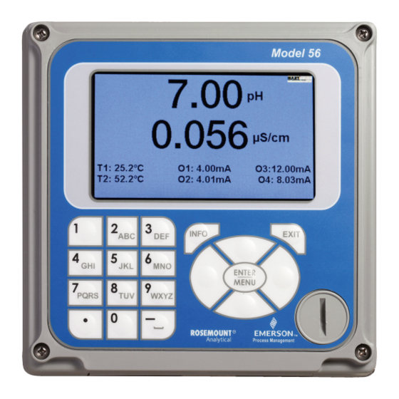
- Page 1 Instruction Manual LIQ-MAN-56 Rev. D April 2017 Rosemount ™ Advanced Dual-Input Analyzer...
- Page 3 Essential Instructions Read this page before proceeding Your instrument purchase from Emerson is one of the finest available for your particular application. These instruments have been designed, and tested to meet many national and international standards. Experience indicates that its perform- ance is directly related to the quality of the installation and knowledge of the user in operating and maintaining the instru- ment.
- Page 4 CAUTION This product generates, uses, and can radiate radio frequency energy and thus can cause radio com- munication interference. Improper installation, or operation, august increase such interference. As temporarily permitted by regulation, this unit has not been tested for compliance within the limits of Class A computing devices, pursuant to Subpart J of Part 15, of FCC Rules, which are designed to pro- vide reasonable protection against such interference.
- Page 5 Section i: Quick Start Guide 1. Refer to Section 2.0 for mechanical installation instructions. Wire sensor(s) to the signal boards. See Section 3.0 for wiring instructions. Refer to the sensor instruction sheet for additional details. Make current output, alarm relay and power connections 3.
- Page 6 Notes 08/11 This is the initial release of the product manual. The manual has been reformatted to reflect the Emerson documentation style and updated to reflect any changes in the product offering. 11/12 Add new feature - configuration transfer via USB. Add new section for existing features - PID control and TPC relay activation, Non-Incendive Field Wiring drawings.
-
Page 7: Table Of Contents
Instruction Manual Table of Contents LIQ-MAN-56 April 2017 Contents Section 1: Description and Specifications 1.1 Features and Applications ................1 1.2 Enhanced Features ..................2 1.3 Specifications-General ..................3 1.4 Contacting Conductivity .................6 1.5 Toroidal Conductivity ..................7 1.6 pH/ORP ......................8 1.7 Flow ........................9 1.8 4-20 mA Current Input..................9 1.9 Chlorine......................10 1.10 Dissolved Oxygen ..................12... - Page 8 Table of Contents Instruction Manual April 2017 LIQ-MAN-56 Section 6: Programming - Measurements 6.1 Programming Measurements – Introduction ..........43 6.2 pH .........................43 6.3 ORP ......................44 6.4 Contacting Conductivity................45 6.5 Toroidal Conductivity ..................46 6.6 Chlorine......................47 6.7 Dissolved Oxygen ..................50 6.8 Dissolved Ozone ...................51 6.9 Turbidity .......................51 6.10 Flow ......................52 6.11 Current Input ....................52...
- Page 9 Instruction Manual Table of Contents LIQ-MAN-56 April 2017 Section 11: HART Communications ® 11.1 Introduction ....................87 11.2 Physical Installation and Configuration ............88 11.3 Measurements Available via HART ..............89 11.4 Diagnostics Available via HART ..............90 11.5 HART Hosts ....................91 11.6 Wireless Communication using the 56............94 11.7 Field Device Specification (FDS) ..............94 Section 12: Profibus Communications 12.1 General ......................95...
- Page 10 Table of Contents Instruction Manual April 2017 LIQ-MAN-56...
-
Page 11: Section 1: Description And Specifications
Instruction Manual Section 1: Description and Specifications LIQ-MAN-56 April 2017 Section 1: Description and Specifications Features and Applications This multi-parameter unit serves industrial, commercial and municipal applications with the widest range of liquid measurement inputs and digital communications available. The 56 advanced dual-input analyzer supports continuous measurement of liquid analytical inputs from one or two sensors. -
Page 12: Enhanced Features
Section 1: Description and Specifications Instruction Manual April 2017 LIQ-MAN-56 Diagnostics: The analyzer continuously monitors itself and the sensor(s) for fault and warning conditions. A display banner flashes red to indicate a Fault condition and yellow for a Warning condition to visually alert field personnel. Details and troubleshooting information for any specific fault or warning can be readily accessed by pressing the INFO key. -
Page 13: Specifications-General
When commissioned with the THUM Adaptor, 56 HART units can communicate on ® Emerson wireless networks using HART 7 wireless protocol. Smart-Enabled pH: Rosemount SMART pH capability can eliminate field calibration of pH probes through automatic upload of calibration data and history – fully calibrating the pH loop. - Page 14 Section 1: Description and Specifications Instruction Manual April 2017 LIQ-MAN-56 Hazardous Location Approvals: Options for CSA: 02, 03, 20, 21, 22, 24, 25, 26, 27, 30, 31, 32, 34, 35, 36, 37, 38, HT and DP Class I, Division 2, Groups A, B, C, & D Class Il, Division 2, Groups E, F, &...
- Page 15 Instruction Manual Section 1: Description and Specifications LIQ-MAN-56 April 2017 Outputs: Four 4-20 mA or 0-20 mA isolated current outputs. Fully scalable. Max Load: 550 Ohms. Output 1 superimposes the HART digital signal. Outputs can be programmed for ® PID control. Output dampening can be enabled with time constants from 0 to 999 seconds. HART digital communications transmitted via current output 1 is standard on all units (option code HT).
-
Page 16: Contacting Conductivity
Section 1: Description and Specifications Instruction Manual April 2017 LIQ-MAN-56 Contacting Conductivity (Codes -20 and -30) Measures conductivity in the range 0 to 600,000 µS/cm (600 mS/cm). Measurement choices are conductivity, resistivity, total dissolved solids, salinity, and % concentration. Temperature compensation can be disabled, allowing the analyzer to display raw conductivity. -
Page 17: Toroidal Conductivity
Instruction Manual Section 1: Description and Specifications LIQ-MAN-56 April 2017 Toroidal Conductivity (Codes -21 and -31) Measures conductivity in the range of 1 (one) µS/cm to 2,000,000 µS/cm (2 S/cm). Measurement choices are conductivity, resistivity, total dissolved solids, salinity, and % concentration. Temperature compensation can be disabled, allowing the analyzer to display raw conductivity. -
Page 18: Ph/Orp
Section 1: Description and Specifications Instruction Manual April 2017 LIQ-MAN-56 pH/ORP (Codes -22 and -32) For use with any standard pH or ORP sensors. Measurement choices are pH, ORP, Redox, Ammonia, Fluoride or custom ISE. The automatic buffer recognition feature uses stored buffer pH values and their temperature curves for the most common buffer standards available worldwide. -
Page 19: Flow
Instruction Manual Section 1: Description and Specifications LIQ-MAN-56 April 2017 Flow (Code -23 and -33) For use with most pulse signal flow sensors, the 56 user-selectable units of measurement include flow rates in GPM (gallons per minute), GPH (gallons per hour), cu ft/min (cubic feet per min), cu ft/hour (cubic feet per hour), LPM (liters per minute), LPH (liters per hour), or m3/hr (cubic meters per hour), and velocity in ft/sec or m/sec. -
Page 20: Chlorine
Section 1: Description and Specifications Instruction Manual April 2017 LIQ-MAN-56 Chlorine (Code -24 and -34) Free and Total Chlorine The 56 is compatible with the 499ACL-01 free chlorine sensor and the 499ACL-02 total chlorine sensor. The 499ACL-02 sensor must be used with the TCL total chlorine sample conditioning system. - Page 21 Instruction Manual Section 1: Description and Specifications LIQ-MAN-56 April 2017 pH-Independent Free Chlorine The 56 is compatible with the 498CL-01 pH-independent free chlorine sensor. The 498CL-01 sensor is intended for the continuous determination of free chlorine (hypochlorous acid plus hypochlorite ion) in water. The primary application is measuring chlorine in drinking water. The sensor requires no acid pre-treatment, nor is an auxiliary pH sensor required for pH correction.
-
Page 22: Dissolved Oxygen
Section 1: Description and Specifications Instruction Manual April 2017 LIQ-MAN-56 1.10 Dissolved Oxygen (Codes -25 and -35) The 56 is compatible with the 499ADO, 499ATrDO, Hx438, Gx438 and BX438 dissolved oxygen sensors and the 4000 percent oxygen gas sensor. The 56 analyzer displays dissolved oxygen in ppm, mg/L, ppb, µg/L, % saturation, % O in gas, ppm O in gas. -
Page 23: Turbidity
Instruction Manual Section 1: Description and Specifications LIQ-MAN-56 April 2017 1.12 Turbidity (Codes -27 and -37) The 56 instrument is available in single and dual turbidity configurations for the Clarity II turbidimeter. It is intended for the determination of turbidity in filtered drinking water. The other components of the Clarity II turbidimeter –... -
Page 24: Ordering Information
Section 1: Description and Specifications Instruction Manual April 2017 LIQ-MAN-56 1.13 Ordering Information The 56 Analyzer offers single or dual sensor input with an unrestricted choice of dual measurement combinations. Measurements capabilities include pH/ORP, Resistivity/ Conductivity, % Concentration, Total Chlorine, Free Chlorine, Monochloramine, Dissolved Oxygen, Dissolved Ozone, Turbidity, Pulse Flow, Temperature, and 4-20mA input. -
Page 25: Section 2: Installation
Instruction Manual Section 2: Installation LIQ-MAN-56 April 2017 Section 2.0 – Installation Unpacking and Inspection Inspect the shipping container. If it is damaged, contact the shipper immediately for instructions. Save the box. If there is no apparent damage, unpack the container. Be sure all items shown on the packing list are present. - Page 26 Section 2: Installation Instruction Manual April 2017 LIQ-MAN-56 Fig. 2-1 Panel Mounting Installation dimensions MILLIMETER INCH Installation...
- Page 27 Instruction Manual Section 2: Installation LIQ-MAN-56 April 2017 Fig. 2-2 Pipe and Wall Mounting Installation dimensions MILLIMETER INCH Shown with Mounting Kit PN 23820-00 Installation...
- Page 28 Section 2: Installation Instruction Manual April 2017 LIQ-MAN-56 Fig. 2-3 FM Non-incendive field wiring installation for the 56-27-37 Analyzer Installation...
- Page 29 Instruction Manual Section 2: Installation LIQ-MAN-56 April 2017 Fig. 2-4 CSA Non-incendive field wiring installation ASSY 24236- ASSY 24355- ASSY 24312- ASSY 24203- R75 R73 Installation...
- Page 30 Section 2: Installation Instruction Manual April 2017 LIQ-MAN-56 Installation...
-
Page 31: Section: 3 Wiring
Instruction Manual Section 3: Wiring LIQ-MAN-56 April 2017 Section 3.0 Wiring General The 56 is easy to wire. It includes removable connectors and slide-out signal input boards The front panel is hinged at the bottom. The panel swings down for easy access to the wiring locations. -
Page 32: Preparing Conduit Openings
Section 3: Wiring Instruction Manual April 2017 LIQ-MAN-56 Preparing Conduit Openings There are six conduit openings in all configurations of 56 analyzer. (Note that four of the openings will be fitted with plugs upon shipment.) Conduit openings accept 1/2-inch conduit fittings or PG13.5 cable glands. To keep the case watertight, block unused openings with Type 4X or IP66 conduit plugs. - Page 33 Instruction Manual Section 3: Wiring LIQ-MAN-56 April 2017 3.4.4 Sensor wiring to signal boards Wire the correct sensor leads to the measurement board using the lead locations marked directly on the board. After wiring the sensor leads to the signal board, carefully slide the wired board fully into the enclosure slot and take up the excess sensor cable through the cable gland.
- Page 34 Section 3: Wiring Instruction Manual April 2017 LIQ-MAN-56 FIGURE 3-1 Power Wiring for 56 24 VDC Power Supply (-02 order code) PN 24365-00 FIGURE 3-2 Power Wiring for 56 85-264 VAC Power Supply (-03 order code) PN 24358-00 Wiring...
- Page 35 Instruction Manual Section 3: Wiring LIQ-MAN-56 April 2017 FIGURE 3-3 Output Wiring for 56 Main PCB PN 24308-00 Wiring...
- Page 36 Section 3: Wiring Instruction Manual April 2017 LIQ-MAN-56 Figure 3-4 56 Recommended Wire Entry Points Figure 3-5 56 Recommended Wire Entry and THUM Adaptor Installation Wiring...
- Page 37 Instruction Manual Section 3: Wiring LIQ-MAN-56 April 2017 Figure 3-6 Contacting Conductivity signal board and Sensor Cable Leads Figure 3-7 Toroidal Conductivity Signal board and Sensor Cable Leads Wiring...
- Page 38 Section 3: Wiring Instruction Manual April 2017 LIQ-MAN-56 Figure 3-8 pH/ORP/ISE Signal Board and Sensor Cable Leads Figure 3-9 Amperometric signal (Chlorine, Oxygen, Ozone) board and Sensor cable leads Wiring...
- Page 39 Instruction Manual Section 3: Wiring LIQ-MAN-56 April 2017 Figure 3-10 Turbidity Signal Board with Plug-in Sensor Connection Figure 3-11 Flow/Current Input Signal Board and Sensor Cable Leads Wiring...
- Page 40 Section 3: Wiring Instruction Manual April 2017 LIQ-MAN-56 Wiring...
-
Page 41: Section 4: Display And Operation
Instruction Manual Section 4: Display and Operation LIQ-MAN-56 April 2017 Section 4.0 Display and Operation User Interface The 56 has a large display which shows two live measurement readouts in large digits and up to six additional process variables or diagnostic parameters concurrently. -
Page 42: Menu System
Section 4: Display and Operation Instruction Manual April 2017 LIQ-MAN-56 Display and Operation... -
Page 43: Usb Data Port
Instruction Manual Section 4: Display and Operation LIQ-MAN-56 April 2017 functions. To find a menu item, use the directional Navigation keys to highlight a menu item. Press ENTER/MENU and simply direct the cursor to the desired operation and follow the screen prompts. Pressing the BACK screen control available on some menu screens will revert to the immediate previous menu screen. - Page 44 Section 4: Display and Operation Instruction Manual April 2017 LIQ-MAN-56 4. With the 56 analyzer powered, remove the NEMA cap from the front display by inserting a coin into the cap’s vertical slot and rotating counterclockwise. Remove the USB cap to access the data port.
-
Page 45: Software Upgrade
Instruction Manual Section 4: Display and Operation LIQ-MAN-56 April 2017 Software Upgrade 4.7.1 Description All 56 advanced analyzers with serial number J12- or later (October 2012) allow software upgrades using the device’s USB data port. To download and install software upgrades, refer Liquid Software Download. - Page 46 Section 4: Display and Operation Instruction Manual April 2017 LIQ-MAN-56 transfer is done by using a version 2.0 USB flash drive (USB memory stick) for downloading the existing configuration and uploading to another instrument. 4.8.2 Transfer Configuration Process User Notes 1.
-
Page 47: Section 5: Programming The Analyzer - Basics
Instruction Manual Section 5: Programming Basics LIQ-MAN-56 April 2017 Section 5.0. Programming the Analyzer - Basics General Typical programming steps include the following listed procedures. Each of these programming functions are easily and quickly accomplished using the intuitive menu systems. •... -
Page 48: Programming Temperature
Section 5: Programming Basics Instruction Manual April 2017 LIQ-MAN-56 To change the measurement type, measurement units, or temperature units, access the Reset screens by pressing ENTER/MENU from the main screen. To change the measurement type, measurement units, or temperature units, access the Program screens by pressing ENTER/MENU from the main screen. -
Page 49: Setting A Security Code
Instruction Manual Section 5: Programming Basics LIQ-MAN-56 April 2017 Setting a Security Code The security codes prevent accidental or unwanted changes to program settings, displays, and calibration. The 56 has two levels of security code to control access and use of the instrument to different types of users. -
Page 50: Using Hold
Section 5: Programming Basics Instruction Manual April 2017 LIQ-MAN-56 Using Hold The analyzer output is always proportional to measured value. To prevent improper operation of systems or pumps that are controlled directly by the current output, place the analyzer in hold before removing the sensor for calibration and maintenance. - Page 51 Instruction Manual Section 5: Programming Basics LIQ-MAN-56 April 2017 The following relay functions can be programmed to any relay from the Configure Relay screen: 1. assign a relay 2. define a relay function 3. assign a Measurement 4. set relay logic 5.
- Page 52 Section 5: Programming Basics Instruction Manual April 2017 LIQ-MAN-56 This section provides details to simulate relay action. To simulate relays, access the Program screen by pressing ENTER/MENU from the main screen and then select the Relay tab. To simulate alarm relay conditions, access the Simulate Relay Action screen by pressing ENTER/MENU from the main Relay programming screen.
-
Page 53: Section 6: Programming - Measurements
Instruction Manual Section 6: Programming Measurements LIQ-MAN-56 April 2017 Section 6.0 Programming - Measurements Programming Measurements – Introduction The 56 automatically recognizes each installed measurement board upon first power-up and each time the analyzer is powered. Completion of Quick Start screens upon first power up enable measurements, but additional steps august be required to program the analyzer for the desired measurement application. -
Page 54: Orp
Section 6: Programming Measurements Instruction Manual April 2017 LIQ-MAN-56 7. Enabling pH sensor diagnostics To configure the pH measurement board, access the Program screen by pressing ENTER/MENU from the main screen and then select the Measurement tab. 1. To Select a Measurement type, se- lect from: pH, ORP, Redox, Ammo- nia, Fluoride, and Custom ISE and press ENTER/MENU. -
Page 55: Contacting Conductivity
Instruction Manual Section 6: Programming Measurements LIQ-MAN-56 April 2017 filter, enter 0-999 seconds and press ENTER/MENU. 4. To program Reference Impedance. Select Low or High and press ENTER/MENU. 5. To choose the wiring scheme, Select Normal or Reference to Ground and press ENTER/MENU. -
Page 56: Toroidal Conductivity
Section 6: Programming Measurements Instruction Manual April 2017 LIQ-MAN-56 8. To change the Temperature compensation Slope, enter the linear temperature coefficient expressed as X.XX% / °C and press ENTER/MENU. 9. To program the Reference Temperature for Manual temperature compensation (not from probe RTD), enter the Reference temp expressed as XX.X °C and press ENTER/MENU. -
Page 57: Chlorine
Instruction Manual Section 6: Programming Measurements LIQ-MAN-56 April 2017 7. To program the Reference Temperature for Manual temperature compensation (not from probe RTD), enter the Reference temp expressed as XX.X °C and press ENTER/MENU. 8. To Override the default input filter, enter 0-999 seconds and press ENTER/MENU. 9. - Page 58 Section 6: Programming Measurements Instruction Manual April 2017 LIQ-MAN-56 5. To program for Manual pH correction, enter the pH value and press ENTER/MENU. 6. To Override the default input filter, enter 0-999 seconds and press ENTER/MENU. 7. To use Dual Slope Calibration, select Enable or Disable and press ENTER/MENU. 6.6.2 Total chlorine measurement programming This Chlorine sub-section describes how to configure the 56 analyzer for Total Chlorine...
- Page 59 Instruction Manual Section 6: Programming Measurements LIQ-MAN-56 April 2017 1. To program the Measurement type, select Free Chlorine, pH Ind Free Cl., Total Cl, or Monochloramine and press ENTER/MENU. 2. To program the Measurement Units: select ppm mg/L and press ENTER/MENU. 3.
-
Page 60: Dissolved Oxygen
Section 6: Programming Measurements Instruction Manual April 2017 LIQ-MAN-56 Oxygen Measurement Programming This section describes how to configure the 56 analyzer for dissolved and gaseous oxygen measurement using amperometric oxygen sensors. The following programming and configuration functions are covered: 1. Sensor type: Select Water/Waste, Trace. -
Page 61: Dissolved Ozone
Instruction Manual Section 6: Programming Measurements LIQ-MAN-56 April 2017 Ozone Measurement Programming This section describes how to configure the 56 analyzer for ozone measurement using amperometric ozone sensors. The following programming and configuration functions are covered: 1. Units: ppm Select ppm, mg/L, ppb, µg/L 2. -
Page 62: Flow
Section 6: Programming Measurements Instruction Manual April 2017 LIQ-MAN-56 6.11 Flow Measurement Programming This section describes how to configure the 56 analyzer for flow measurement when used with a compatible pulse flow sensor. The following programming and configuration functions are covered: To program pulse flow, scroll to the desired item and press ENTER. - Page 63 Instruction Manual Section 6: Programming Measurements LIQ-MAN-56 April 2017 1. To override the default the Measurement type (Flow) select mA current input and press ENTER/MENU. 2. To program the mA Input type, Select Temperature, Pressure, Flow or other and press ENTER/MENU. 3.
- Page 64 Section 6: Programming Measurements Instruction Manual April 2017 LIQ-MAN-56...
-
Page 65: Section 7: Pid Control
Instruction Manual Section 7: PID Control LIQ-MAN-56 April 2017 Section 7.0 PID Control Introduction 7.1.1 Measurement and Set Point (Feedback Control) The 56 controller is given two items of information: measurement and set point. The controller reacts to the difference in value of these two signals and produces an analog output signal to eliminate that difference. - Page 66 Section 7: PID Control Instruction Manual April 2017 LIQ-MAN-56 Example of direct acting control: Lower the pH of a solution at 10 pH by adding acid to control it at 8 pH with the Gain parameter assumed to be 1.0. The higher the measured pH, the more acid is required to lower the pH toward the setpoint, but as the pH approaches the setpoint less acid is required: Fig.
- Page 67 Instruction Manual Section 7: PID Control LIQ-MAN-56 April 2017 Fig. 7-4 Example of Reverse Acting Control 7.1.3 Proportional Bias Most processes require that the measured variable be held at the set point. The proportional mode alone will not automatically do this, if an output greater than 0% is needed to keep the PV at setpoint.
- Page 68 Section 7: PID Control Instruction Manual April 2017 LIQ-MAN-56 Fig. 7-6 Reverse Acting Control with Bias 7.1.4 Proportional Plus Integral (Reset) For the automatic elimination of deviation, Integral mode, also referred to as Reset, is used. The proportional function is modified by the addition of automatic reset, rather than a constant Bias value.
-
Page 69: Pid Setup
Instruction Manual Section 7: PID Control LIQ-MAN-56 April 2017 7.1.5 Derivative Mode (Rate) Derivative mode provides a 3rd control mode, which responds to the rate of change of the Proportional control output, multiplied by the Derivative parameter D which has units of seconds. - Page 70 Section 7: PID Control Instruction Manual April 2017 LIQ-MAN-56 Basic Definitions • Output – Select the analog output (1 through 4) to be configured for PID control. • Analog/PID/Simulate – Choose PID • Assign – Select the Measurement to be controlled. Note: This measurement can also be a 4-20 mA signal input brought in by the flow/ 4-20 mA board.
- Page 71 Instruction Manual Section 7: PID Control LIQ-MAN-56 April 2017 Note: If you want the control output to increase as PV (in this case pH) increases, URV should be greater than LRV. This is direct acting control action. Examples of direct acting control are the addition of acid to decrease pH and adding water to a solution to decrease the concentration.
- Page 72 Section 7: PID Control Instruction Manual April 2017 LIQ-MAN-56 Transport Time Parameters: Basic Definitions • Transport Time (On/Off) – Turns the Transport Time feature on or off. • Transport Time (range 1 to 600 seconds) – When Transport Time is turned On; a control appears at the right of it, which allows the value of the Transport Time to be enter.
-
Page 73: Section 8: Time Proportional Control
Instruction Manual Section 8: Time Proportional Control LIQ-MAN-56 April 2017 Section 8.0 Time Proportional Control Introduction 8.1.1 Time Proportional Control Time Proportional Control is more commonly known as Duty Cycle or Pulse Width Modulation. It applies PID control to the activation of a relay rather than using an analog output. The TPC output is defined as the percent of time that a relay is on (% On Time), during a user selected time period (Time Period). -
Page 74: Tpc Setup
Section 8: Time Proportional Control Instruction Manual April 2017 LIQ-MAN-56 TPC Setup 8.2.1 Selecting TPC Select TPC control, the relay to be used, and the measurement to be controlled from the main relay setup window: Basic Definitions • Relay – Select the relay (1 through 4) to be use for TPC control. •... - Page 75 Instruction Manual Section 8: Time Proportional Control LIQ-MAN-56 April 2017 PID Control Parameters: Basic Definitions • Setpoint – Select the desired setpoint. • URV – The value of PV (in the above example, 14.00 pH) at which the control will be 100% On Time.
- Page 76 Section 8: Time Proportional Control Instruction Manual April 2017 LIQ-MAN-56...
-
Page 77: Section 9: Alarm Relay Functions
Instruction Manual Section 9: Alarm Relay Functions LIQ-MAN-56 April 2017 Section 9.0 Alarm Relay Functions General An alarm is a relay that closes a set of contact points (a switch) inside the analyzer. In doing so, the relay closes an electrical circuit and turns on a device wired to the contacts. The 56 Advanced Analyzer has four alarm relays and seven relay control functions. -
Page 78: Delay Timer
Section 9: Alarm Relay Functions Instruction Manual April 2017 LIQ-MAN-56 9.2.2 Setup Access high/low concentration (setpoint) alarms by pressing ENTER/MENU from the main screen and then Program/Relays/Configure Relay. From the main relay programming screen, program this feature as follows: 1. Relay: Assign a relay by highlighting the desired relay 1-4 and press ENTER/MENU. 2. - Page 79 Instruction Manual Section 9: Alarm Relay Functions LIQ-MAN-56 April 2017 A schematic of the Delay Timer operation is shown: Figure 9-2. Delay Timer Alarm operation measurement high alarm deadband time on time delay time 9.3.2 Setup Access Delay Timer by pressing ENTER/MENU from the main screen and then Program/Relays/ Configure Relay.
-
Page 80: Bleed And Feed
Section 9: Alarm Relay Functions Instruction Manual April 2017 LIQ-MAN-56 Table 9-3. Defaults and programmable limits Relay Function Limits and Selections Default Delay Timer Logic Low/High High Setpoint Deadband 0.000 Normal state Close/Open Open * See Appendix 1 – HART and Device Variables Bleed and Feed 9.4.1 Description:... -
Page 81: Totalizer Based Relay Activation
Instruction Manual Section 9: Alarm Relay Functions LIQ-MAN-56 April 2017 5. Setpoint: Enter the desired setpoints value. This will activate an alarm event when the process measurement reaches the entered setpoint value. Press ENTER/MENU. See Table 9-3 for entry limits. 6. -
Page 82: Interval Timer
Section 9: Alarm Relay Functions Instruction Manual April 2017 LIQ-MAN-56 A typical application for totalized flow relay activation is controlling chemical dosing in reactors. A schematic of the Totalizer timer operation is shown: Figure 9-4. Totalizer alarm operation relay on time X volume X volume... - Page 83 Instruction Manual Section 9: Alarm Relay Functions LIQ-MAN-56 April 2017 Interval time has expired, the analyzer activates hold mode on the assigned measurement and the relay is energized for the On time period. A schematic of the Interval timer operation is shown: Figure 9-5.
-
Page 84: Date And Time Activation
Section 9: Alarm Relay Functions Instruction Manual April 2017 LIQ-MAN-56 Date and Time Activation 9.7.1 Description: This relay feature allows programming of 1 to 4 relays to activate on an assigned day of the week and time of day or night for an assigned interval. They function like sprinkler timers. The programmable timeframe cycle is two weeks. -
Page 85: Section 10: Calibration
Instruction Manual Section 10: Calibration LIQ-MAN-56 April 2017 Section 10.0 Calibration 10.1 Calibration – Introduction Calibration is the process of adjusting or standardizing the analyzer to a lab test or a calibrated laboratory instrument, or standardizing to some known reference (such as a commercial buffer). -
Page 86: Orp Calibration
Section 10: Calibration Instruction Manual April 2017 LIQ-MAN-56 4. Entering A Known Slope Value - pH Slope calibration with manual entry of known slope value 1. To Auto Calibrate the pH loop using 2 point buffer calibration with auto buffer recognition, select Auto Buffer and follow the step-by-step proce- dures displayed on-screen. -
Page 87: Contacting Conductivity Calibration
Instruction Manual Section 10: Calibration LIQ-MAN-56 April 2017 10.4 Contacting Conductivity Calibration New conductivity sensors rarely need calibration. The cell constant printed on the label is sufficiently accurate for most applications. CALIBRATING AN IN-SERVICE CONDUCTIVITY SENSOR After a conductivity sensor has been in service for a period of time, recalibration august be necessary. -
Page 88: Toroidal Conductivity Calibration
Section 10: Calibration Instruction Manual April 2017 LIQ-MAN-56 1. To Zero Calibrate the analyzer with the sensor attached, follow the step- by-step procedures displayed on-screen. 2. To perform an In-Process Calibration of the conductivity loop by Standardizing the sensor to a known conductivity, follow the step-by-step procedures displayed on-screen. - Page 89 Instruction Manual Section 10: Calibration LIQ-MAN-56 April 2017 10.6 Calibration —Chlorine With a Chlorine measurement board and the appropriate sensor, the 56 can measure any of four variants of Chlorine: • Free Chlorine • Total Chlorine • Monochloramine • pH-independent Free Chlorine The section describes how to calibrate any compatible amperometric chlorine sensor.
-
Page 90: Chlorine Calibration
Section 10: Calibration Instruction Manual April 2017 LIQ-MAN-56 10.6.2 Calibration — Total Chlorine Total chlorine is the sum of free and combined chlorine. The continuous determination of total chlorine requires two steps. First, the sample flows into a conditioning system (TCL) where a pump continuously adds acetic acid and potassium iodide to the sample. - Page 91 Instruction Manual Section 10: Calibration LIQ-MAN-56 April 2017 10.6.3 Calibration — Monochloramine A monochloramine sensor generates a current directly proportional to the concentration of monochloramine in the sample. Calibrating the sensor requires exposing it to a solution containing no monochloramine (zero standard) and to a solution containing a known amount of monochloramine (full-scale standard).
-
Page 92: Oxygen Calibration
Section 10: Calibration Instruction Manual April 2017 LIQ-MAN-56 10.6.4 pH-Independent Free Chlorine Measurement A free chlorine sensor generates a current directly proportional to the concentration of free chlorine in the sample. Calibrating the sensor requires exposing it to a solution containing no chlorine (zero standard) and to a solution containing a known amount of chlorine (full-scale standard). - Page 93 Instruction Manual Section 10: Calibration LIQ-MAN-56 April 2017 atmospheric oxygen in water as a function of temperature and barometric pressure is well known, the natural choice for a full-scale standard is air-saturated water. However, air-saturated water is difficult to prepare and use, so the universal practice is to use air for calibration. From the point of view of the oxygen sensor, air and air-saturated water are identical.
-
Page 94: Ozone Calibration
Section 10: Calibration Instruction Manual April 2017 LIQ-MAN-56 1. To Zero Calibrate the analyzer with the sensor attached, follow the step- by-step procedures displayed on- screen. 2. To Air Cal Calibrating the sensor in a water-saturated air sample, follow the step-by-step procedures dis- played on-screen. -
Page 95: Calibrating Temperature
Instruction Manual Section 10: Calibration LIQ-MAN-56 April 2017 10.9 Calibrating Temperature Most liquid analytical measurements require temperature compensation (except ORP). The 56 performs temperature compensation automatically by applying internal temperature correction algorithms. Temperature correction can also be turned off. If temperature correction is off, the 56 uses the manual temperature entered by the user in all temperature correction calculations. -
Page 96: Pulse Flow
Section 10: Calibration Instruction Manual April 2017 LIQ-MAN-56 1. To calibrate the turbidity loop using Slope Calibration with pure water and a standard of known turbidity, follow the step-by-step procedures displayed on-screen. 2. To calibrate the turbidity loop using Standardize Calibration by Standard- izing the sensor to a known turbidity, follow the step-by-step procedures displayed on-screen. -
Page 97: Introduction
Instruction Manual Section 10: Calibration LIQ-MAN-56 April 2017 Section 11.0 HART Communications ® 11.1 Introduction The 56 can communicate with a HART host using HART Revision 5 or HART Revision 7. The revision of HART used by the 56 can be selected using the keypad/display or a HART master such as AMS or the 475 Handheld Communicator. -
Page 98: Physical Installation And Configuration
Section 11: HART Communications Instruction Manual April 2017 LIQ-MAN-56 11.2 Physical Installation and Configuration 11.2.1 HART Wiring and Output Configuration HART communications is superimposed on Analog Output 1 for all of the measurements and parameters of the 56. The 4-20 mA current of Analog Output 1 can be configured by the keypad display to be powered by the 56 (Output 1 power: Internal), or by an external 24 VDC power supply, or an I/O that provides power (Output 1 power: External). -
Page 99: Measurements Available Via Hart
Instruction Manual Section 11: HART Communications LIQ-MAN-56 April 2017 • Output 1 Power – Select “Internal” to power Output 1 with the 56. Select “External” to power the current loop with an external power supply, e.g. a host I/O that provides power (source) to the transmitter (sink). -
Page 100: Diagnostics Available Via Hart
Section 11: HART Communications Instruction Manual April 2017 LIQ-MAN-56 11.4 Diagnostics Available via HART 11.4.1 Status Information -- Device Status Bits Bit 0 Primary Variable out of Limits: This bit is set when PV is out of its limits. Bit 1 Non-primary Variable out of Limits: This bit is set when non PV is out of its limits. -
Page 101: Hart Hosts
Instruction Manual Section 11: HART Communications LIQ-MAN-56 April 2017 0x1100). This bit is set if any Device Variable is in an Alarm or Warning State. The host should identify the Device Variable(s) causing this to be set using the Device Variable Status indicators. - Page 102 Section 11: HART Communications Instruction Manual April 2017 LIQ-MAN-56 FIGURE 11-2 Device Variables and Dynamic Variables FIGURE 11-3 Diagnostic Messages (Additional Transmitter Status) HART Communications...
- Page 103 Instruction Manual Section 11: HART Communications LIQ-MAN-56 April 2017 FIGURE 11-4 Configuration FIGURE 11-5 Calibration HART Communications...
-
Page 104: Field Device Specification (Fds)
Section 11: HART Communications Instruction Manual April 2017 LIQ-MAN-56 be accessed wirelessly, making it possible to have the measurements and benefits of HART communication in locations where running cable would be difficult or prohibitively expensive. Although HART 5 or HART 7 can burst the Dynamic Variables (PV, SV, TV, & QV), HART 7 should be used with the THUM because up to 8 Device Variables can be continually burst using Command 9. -
Page 105: Section 12: Profibus Communications
Instruction Manual Section 12: Profibus Communications LIQ-MAN-56 April 2017 Section 12.0 Profibus Communications 12.1 General The 56 can communicate using Profibus DP-V1 by purchasing a 56 with a Profibus communication board installed (model code 56-PC-02-DP), or by adding a Profibus communications board to the standard 56 with HART communications. -
Page 106: Profibus Communications
Section 12: Profibus Communications Instruction Manual April 2017 LIQ-MAN-56 • The DP device supports the function Set_Slave_Add for setting the slave address via the PROFIBUS. The slave address for the 56 can be set automatically or manually by the Profibus master. The DP device supports DP-V0 cyclic services and Identification and Maintenance (I&M) function: - I&M 0 •... - Page 107 Instruction Manual Section 12: Profibus Communications LIQ-MAN-56 April 2017 12.3 Profibus Communications 12.3.1 Configuring the 56 for Profibus Communications Baud Rates The 56 supports all the baud rates of Profibus DP as shown in Table 12.2.1 below. Since the 56 supports transmission rate recognition, it will recognize the baud rate used on the network, and set its own baud rate to match the network’s rate.
- Page 108 Section 12: Profibus Communications Instruction Manual April 2017 LIQ-MAN-56 12.3.2 Profibus Faults and Warnings Faults The 56 displays the following hardware faults associated with problems related to the Profibus board and its connection to the main board: • Profibus board mismatch - The revision of the installed Profibus board is not compati- ble with the main board of the transmitter.
- Page 109 Instruction Manual Section 12: Profibus Communications LIQ-MAN-56 April 2017 Diagnostic Information The 56 provides diagnostic information on Profibus communications, which is accessed by pressing the INFO key and then selecting “Profibus information” to launch the window below: • Address – displays the address being used by the 56 on the network •...
-
Page 110: Data Transmission
Section 12: Profibus Communications Instruction Manual April 2017 LIQ-MAN-56 12.4 Data Transmission General The 56 uses RS-485 communication technology for transmission. When messages are transmitted on Profibus networks, for word transfer (more than one byte), the high byte is transferred first, followed by the low byte (Big-Endian/Motorola format). 56 Modules The details of measurement modules and relay modules are shown below in the following tables: 12.4.1... - Page 111 Instruction Manual Section 12: Profibus Communications LIQ-MAN-56 April 2017 Table 12-4. Measurement Unit Codes and Units Unit Unit Unit Code Unit Code Unit Code Unit 1001 °C 1212 µA 1364 1002 °F 1213 1423 1034 m3 1243 1424 1038 L 1274 1425 ppth...
- Page 112 Section 12: Profibus Communications Instruction Manual April 2017 LIQ-MAN-56 12.4.2 Relay Modules Relay Modules provide the alarm type, state, logic, assignment, and simulation status as shown in Tables 12-5 to 12-10: Table 12-6. Measurement Modules Data Size Module Module Name Type Bytes Identifiers...
- Page 113 Instruction Manual Section 12: Profibus Communications LIQ-MAN-56 April 2017 Table 12-8. Alarm States Table 12-9. Alarm Logic Table 12-10. Alarm Simulation Code Logic Code State High Alarm Low Alarm De-Energize USP Alarm (Contacting Energize Conductivity Only) Table 12-11. Alarm Assignment Codes ensor 1 Sensor 2 Variable Assigned...
- Page 114 Section 12: Profibus Communications Instruction Manual April 2017 LIQ-MAN-56 12.4.3 Transmitter Diagnostic Bits The 56 transmits diagnostic bits associated with main board and signal board faults and warnings, as well as faults and warning specific to the sensors used to make the various measurements.
- Page 115 Instruction Manual Section 12: Profibus Communications LIQ-MAN-56 April 2017 Table 12-13. Main Board Diagnostic Bits – Main Board Warnings Main Board Warnings GSD Descriptor Help Unknown The main board software cannot identify the power supply. Power Supply 1. Check the ribbon cable connections between the power supply board and main board.
- Page 116 Section 12: Profibus Communications Instruction Manual April 2017 LIQ-MAN-56 Table 12-14. Signal Board Diagnostic Bits Diagnostic Bits GSD Descriptor Help Signal Board 1 / 2 40 / 72 SN 1/2 Board The analyzer automatically recognizes the sensor board on power up. Sensor Unknown (Fault) board unknown implies the sensor board is new and not supported or there is a bad connection between the sensor board and the main board.
- Page 117 Instruction Manual Section 12: Profibus Communications LIQ-MAN-56 April 2017 Table 12-14. Signal Board Diagnostic Bits – continued Temperature Faults and Warnings Help Signal Board 1 / 2 Descriptor 48 / 80 SN 1/2 RTD The temperature measuring circuit is open. The RTD is improperly wired or the RTD IN or Open (Fault) RTD RTN are broken.
- Page 118 Section 12: Profibus Communications Instruction Manual April 2017 LIQ-MAN-56 Table 12-14. Signal Board Diagnostic Bits – continued pH / ISE Faults and Warnings Signal GSD Descriptor Help Board 1 / 2 51 / 83 SN 1/2 Ref Z Too The impedance of the reference junction is too high. High (Fault) 1.
- Page 119 Instruction Manual Section 12: Profibus Communications LIQ-MAN-56 April 2017 Table 12-14. Signal Board Diagnostic Bits – continued Conductivity Faults and Warnings Signal GSD Descriptor Help Board 1 / 2 109 / 141 SN 1/2 Out Of Contacting Conductivity Measurements Range Cont/Tor The raw conductance is greater than 1 S.
- Page 120 Section 12: Profibus Communications Instruction Manual April 2017 LIQ-MAN-56 Table 12-14. Signal Board Diagnostic Bits – continued Flow / 4 to 20 mA Input Faults and Warnings Signal GSD Descriptor Help Board 1 / 2 117 / 149 SN 1/2 No Flow The analyzer has sensed no flow for at least ten seconds.
-
Page 121: Installation And Wiring
Instruction Manual Section 12: Profibus Communications LIQ-MAN-56 April 2017 12.5 Installation and Wiring 12.5.1 General This section shows the recommended method of wiring the Profibus cable to the Profibus card of the 56. Recommended Wiring Steps 1. Feed the Profibus cable through a cable gland fitting. Install the cable gland fitting into the enclosure opening on the leftmost side of the enclosure nearest the front of the door hinge. - Page 122 Section 12: Profibus Communications Instruction Manual April 2017 LIQ-MAN-56 3. Remove the 4-lead terminal block which is installed on the Profibus slide-in board. This photo shows the 4-lead terminal block installed onto the board: FIGURE 12-3. Profibus board showing FIGURE 12-4. 4-Lead Terminal Block removable 4-lead terminal block 4.
-
Page 123: Section 13: Maintenance
Instruction Manual Section 13: Maintenance LIQ-MAN-56 April 2017 Section 13.0 Maintenance 13.1 Overview This section gives general procedures for routine maintenance of the 56 advanced analyzer. The analyzer needs almost no routine maintenance. Sensors require periodic inspection and cleaning. The calibration of the transmitter-sensor combination should be checked regularly, and the loop recalibrated if necessary. - Page 124 Section 13: Maintenance Instruction Manual April 2017 LIQ-MAN-56...
-
Page 125: Section 14: Return Of Material
Warranty Repair The following is the procedure for returning instruments still under warranty: 1. Call Emerson for authorization. 2. To verify warranty, supply the factory sales order number or the original purchase order number. In the case of individual parts or sub-assemblies, the serial number on the unit must be supplied. - Page 126 Section 14: Return of Material Instruction Manual April 2017 LIQ-MAN-56...
- Page 127 Instruction Manual Appendix 1: HART and Device Variables LIQ-MAN-56 April 2017 Appendix 1: HART and Device Variables pH Device Variables Assignable to Dynamic Device Variable Name Variable Range Variables Sensor 1 / 2 Measurement Type pH (1) PV, SV, TV or QV 0 to 14 pH ORP (2), Redox (3) PV, SV, TV or QV...
- Page 128 Appendix 1: HART and Device Variables Instruction Manual April 2017 LIQ-MAN-56 Contacting and Toroidal Conductivity Device Variables Device Variable Name Assignable to Dynamic Variables Variable Range Sensor 1 / 2 Measurement Type Conductivity (7) PV, SV, TV or QV 0 to 2000000 µS/cm Resistivity (8) PV, SV, TV or QV 0 to 50000000 ohm-cm...
- Page 129 Instruction Manual Appendix 1: HART and Device Variables LIQ-MAN-56 April 2017 Amperometric Device Variables Device Variable Name Assignable to Dynamic Variables Variable Range Sensor 1 / 2 Measurement Type Salinity (16) PV, SV, TV or QV 0 to 36 ppth Oxygen (17) PV, SV, TV or QV 0 to 100 ppm...
- Page 130 Appendix 1: HART and Device Variables Instruction Manual April 2017 LIQ-MAN-56 Flow / mA Input Device Variables (continued) Device Variable Name Assignable to Dynamic Variables Variable Range Sensor 1 / 2 Measurement Type Scaled mA Input (24) PV, SV, TV or QV As per Configuration Units: Input Type:...
- Page 131 Instruction Manual Appendix 2: HART Status Bits LIQ-MAN-56 April 2017 Appendix 2: HART Status Bits Common Transmitter Status Bits Byte Message Severity Device Status Bits Set Sensor 1 Hardware Error Error Device Status: bit 7, 3 Sensor 1 User Data Error Error Device Status: bit 7, 3 Sensor 1 EEPROM Write Error...
- Page 132 Appendix 2: HART Status Bits Instruction Manual April 2017 LIQ-MAN-56 Common Transmitter Status Bits (continued) Byte Message Severity Device Status Bits Set Analog channel-2 fixed Mode Analog channel-3 fixed Mode Analog channel-4 fixed Mode Main board CPU Error Error Device Status: bit 7, 3 User Data Error Error Device Status: bit 7, 3...
- Page 133 Instruction Manual Appendix 2: HART Status Bits LIQ-MAN-56 April 2017 pH Board Status Bits Byte Message Severity Device Status Bits Set Sensor 1 Reference Impedance Too High Error Device Status: bit 7, 3 Sensor 1 Glass Impedance Too High Error Device Status: bit 7, 3 Sensor 1 Broken Glass Error...
- Page 134 Appendix 2: HART Status Bits Instruction Manual April 2017 LIQ-MAN-56 Amperometric Status Bits Byte Message Severity Device Status Bits Set Sensor 1 Pressure Broken Warning Device Status: bit 4 Sensor 1 Amperometric Board Negative Reading Warning Device Status: bit 4 Sensor 2 Pressure Broken Warning Device Status: bit 4...
- Page 135 Instruction Manual EC Declaration LIQ-MAN-56 April 2017 Note: Please see website for most recent Declaration. EC Declaration...
- Page 136 The Emerson logo is a trademark and service mark of Emerson Electric Co. Rosemount is 8200 Market Blvd. a mark of one of the Emerson family of companies. All other marks are the property of Chanhassen, MN 55317, their respective owners.
Need help?
Do you have a question about the Rosemount 56 and is the answer not in the manual?
Questions and answers
I can’t get the unit to come back within calibration after the membrane and electrolyte was replaced. this is for a DO analyzer model 56
To recalibrate the Emerson Rosemount 56 Dissolved Oxygen (DO) analyzer after replacing the membrane and electrolyte, follow these steps:
1. Access the Calibration Menu: Navigate to the calibration settings on the analyzer.
2. Select Calibration Type: Choose the appropriate calibration method, such as air calibration or a two-point calibration.
3. Set Atmospheric Pressure: If required, configure the atmospheric pressure source (internal or external).
4. Perform Air Calibration: Expose the sensor to air-saturated water or air and allow it to stabilize.
5. Confirm Calibration Values: Ensure the displayed oxygen concentration matches the expected value.
6. Save the Calibration: Confirm and save the calibration settings.
For precise steps, refer to the analyzer’s instruction manual.
This answer is automatically generated