Table of Contents
Advertisement
Quick Links
Setup Guide
Large-Capacity Bipolar Power Supply
Smart Rack System
PBZ-SR Series
1.2 kW model
PBZ20-60 SR
PBZ40-30 SR
PBZ60-20.1 SR
PBZ80-15 SR
1.6 kW model
PBZ20-80 SR
PBZ40-40 SR
PBZ60-26.8 SR
PBZ80-20 SR
2 kW model
PBZ20-100 SR
PBZ40-50 SR
PBZ60-33.5 SR
PBZ80-25 SR
PART NO. Z1-005-860, IB026165
Jan. 2016
Option 3
Turning Off 10
Advertisement
Table of Contents

Related Manuals for Kikusui PBZ20-80 SR


Summary of Contents for Kikusui PBZ20-80 SR
-
Page 1: Table Of Contents
Connecting Devices to Synchronize 22 PBZ40-30 SR Connecting an External Signal Source 23 Using Current Monitor Output 23 PBZ60-20.1 SR PBZ80-15 SR 1.6 kW model PBZ20-80 SR PBZ40-40 SR PBZ60-26.8 SR PBZ80-20 SR 2 kW model PBZ20-100 SR PBZ40-50 SR PBZ60-33.5 SR... - Page 2 If the manual gets lost or soiled, a new copy can be provided for a fee. In either case, please contact Kikusui distributor/agent, and provide the “Kikusui Part No.” given on the cover. The PBZ-SR series Manuals has been prepared with the utmost care;...
-
Page 3: Checking The Package Contents
When you receive the product, check that all accessories are The PBZ-SR has the following options. For information about included and that the accessories have not been damaged options, contact your Kikusui agent or distributor. during transportation. • AC Input power cable (AC8-3P3M-M5C) - Page 4 • The large-capacity bipolar power supplies smart rack sys- accidentally while it is being operated, use the stopper to fix tem PBZ20-60 SR, PBZ20-80 SR, PBZ20-100 SR, PBZ40- the product in place, and lock the casters. 30 SR, PBZ40-40 SR, PBZ40-50 SR, PBZ60-20.1 SR, PBZ60-26.8 SR, PBZ60-33.5 SR, PBZ80-15 SR, PBZ80-20...
-
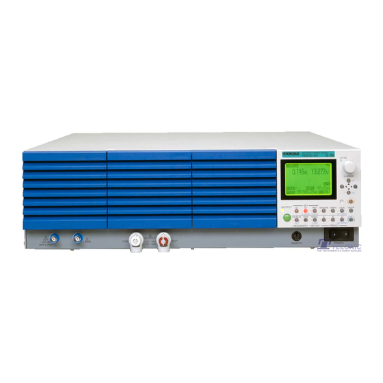
Page 5: Part Names
Part Names Front panel (example of PBZ20-100 SR) Display Handle Master unit EXT SIG IN terminal I MON terminal Slave unit Model name POWER switch Caster * The PBZ-SR series does not have the OUTPUT terminals that are available on Stopper bolt the front panel of individual PBZ power supplies. -
Page 6: Preparation
Preparation This chapter describes how to connect the power cable and how to turn the power on and off. Connecting the Power Cable This product is designed as an equipment of IEC Overvoltage Category II (energy-consuming equipment supplied from the fixed installation) •... - Page 7 Connecting the Power Cable Connect the power cable to the AC input terminal The size of the terminal block screws is M5. Attach appropriate crimping terminals to the power cable. Screw (M3) Screw (M5) (GND) Attach crimping terminals to the switchboard end of the power cable. Use crimping terminals that conform to the switchboard's terminal screws.
-
Page 8: Turning On
Turning On Check that the power cable is correctly connected. Check that the POWER switches on the individual PBZ power supplies are all turned on. PBZ20-100 SR example Turn the POWER switch on. The display shows the model and firmware version, and a self test starts. (Display example) When the self test finishes, if no errors were detected, “PASS”... - Page 9 If an error number is displayed after the self test Follow the remedy that corresponds to the appropriate error number shown in the following table. If following the remedy shown here does not solve the problem, contact your Kikusui agent or distributor.
-
Page 10: Turning Off
The number of parallel operation units Remote sensing on/off (UNIT) (SENSING) PBZ 20-60 SR PBZ 40-30 SR PBZ 60-20.1 SR PBZ 80-15 SR PBZ20-80 SR PBZ40-40 SR PBZ60-26.8 SR PBZ80-20 SR PBZ20-100 SR PBZ40-50 SR PBZ60-33.5 SR PBZ80-25 SR Turning Off Lower the POWER switch lever to turn the power off. -
Page 11: Connecting The Load
Use wires that have diameters that correspond to the output current to connect to the load. Nominal cross- AWG (reference Kikusui-recommended Allowable current sections area cross-section area;... - Page 12 Connecting the Load Cable Connecting the Load Cable Using load cables, connect the load to the PBZ-SR through the output terminals on the rear panel. Possible electric shock. WARNING • Turn the POWER switch off before you touch the OUTPUT terminals. •...
- Page 13 Connecting the Load Cable Attach the output terminal cover. PBZ20-100 SR example Adjust the output terminal cover to the appropriate position, and tighten the screws. Adjust the position so that the space between the cover and cables is small. Influence of Cables When you use the PBZ-SR, you must wire the load and configure the response setting correctly and reduce the inductance.
- Page 14 Connecting the Load Cable How to reduce the effect of wiring • You can reduce the inductance of load cables by using the optional low inductance p. 3 cables (TL02-PLZ, TL03-PLZ, LIC40-2P1M-M6M6 or LIC40-2P2M-M6M6). • If fast transient response is not required, increase the response setting. The value of I/T is reduced, so even if you can’t reduce the load cable’s inductance, you can reduce the induced voltage.
-
Page 15: Using Remote Sensing
Using Remote Sensing Remote sensing is a feature that is used to switch the voltage measurement point of CV/CC mode and the voltage feedback point of CV mode. When remote sensing is enabled, the voltage measurement point of CV/CC mode and the voltage feedback point of CV mode are switched from the rear panel OUTPUT terminals to the contact points of the sensing terminals. - Page 16 Using Remote Sensing Lower the POWER switch lever of the PBZ-SR to turn the power off. On the rear panel, loosen the screws holding the output terminal cover in place, and remove the cover. Screw (M4) Output terminal cover Connect the sensing cables to the sensing terminals. Remove the two short bars from the sensing terminals before connecting the cables.
- Page 17 Using Remote Sensing Attach the OUTPUT terminal cover. Adjust the output terminal cover to the appropriate position, and tighten the screws. Adjust the position so that the space between the cover and cables is small. Connect the sensing cables to the load. Connect by referring to the following information.
- Page 18 Using Remote Sensing If You Are Inserting a Mechanical Switch between the OUTPUT Terminals and the Load If you want to insert a mechanical switch between the OUTPUT terminals and the load, be sure to include the sensing cables in the switch as shown in the figure below and turn on and off the load and sensing cables simultaneously.
-
Page 19: Connecting External Devices
Connecting External Devices This chapter describes how to connect an external controller when you want to control the PBZ-SR externally or remotely. Connecting an External Controller By applying control signals to the rear panel J1 connector, you can control the following aspects of the PBZ-SR. - Page 20 Connecting an External Controller Connect a cable to the J1 connector of the master unit. Attach the rear panel that you removed in step 2 . When you attach the rear panel, pass the cables that you wired to the J1 connector through the open space on the left edge of the panel.
-
Page 21: Connecting An Remote Controller
Connecting an Remote Controller In addition to controlling the PBZ-SR from the front panel, you can control it remotely through the following standard-equipped interfaces. • RS232C interface • GPIB interface • USB interface • LAN interface You cannot control the PBZ-SR through RS232C, GPIB, USB, and LAN at the same time. For details on remote control and how to perform it, see the PBZ Series Communication Interface Manual. -
Page 22: Connecting Devices To Synchronize
Connecting Devices to Synchronize You can use the following synchronization features by connecting multiple products (individual PBZ power supplies or other PBZ-SR series) to the PBZ-SR. • Turn the output of multiple units on and off at the same time. •... -
Page 23: Connecting An External Signal Source
Connecting an External Signal Source By using an external signal, you can create a bipolar amplifier that amplifies the input signal that the PBZ-SR receives through EXT SIG IN (BNC terminal). You can set the gain, the polarity (inverted or not inverted), and the offset of the amplifier. For details on how to use an external signal source, see “Using the EXT SIG IN Signal (External Signal Source)”... - Page 24 The specifications of this product and the contents of this manual are subject to change without prior notice. © 2013 环境保护使用期限 Environment-friendly Use Period 该标记为适用于在中华人民共和国销售的电子信息产品的环境保护使用期限。 只要遵守有关该产品的安全及使用注意事项,从制造年月起计算,在该年度内,就不会对环境污染、人身、财产产生重 大的影响。 产品的废弃请遵守有关规定。 产品的制造年月可以在以下网址中确认。 http://www.kikusui.co.jp/pi/ 有毒有害物质或元素名称及含有標示 Name of hazardous materials and symbol of element in the equipment and quantity 有毒有害物质或元素 部件名称 铅 汞 镉 六价铬 多溴联苯...
Need help?
Do you have a question about the PBZ20-80 SR and is the answer not in the manual?
Questions and answers