Table of Contents
Advertisement
Quick Links
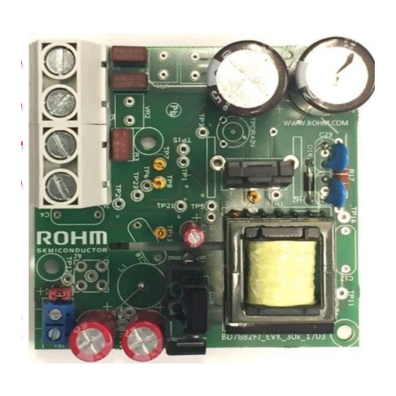
BD7682FJ-EVK-301 EV BOARD USER GUIDE
High voltage input aux power supply ev. Board
1 – 1700V SiC MOSFET SCT2H12NZ
2 – Quasi-resonant controller BD7F682FJ-LB
Board dimensions 80mm x 80mm
Figure 1 – Top and Bottom views
The AUX board is able to operate with both AC and DC input voltages. It is therefore possible to derive the power directly
from the grid or from the system DC link, e.g. after the PFC stage. In case of AC input, the accepted input voltage range
goes from 210 V
to 480 V
AC
mounts screw connections to facilitate the cabling to 3phase input or Vdc input. It is possible to remove the connectors
and use vertical mounting connectors as an example of module board for Aux power supply in a power system.
The simplified schematic of the AUX board is shown in Figure 2.
AC
© 2018 ROHM Co., Ltd.
1
. In case of DC input, the input range goes from 300 V
AC
D
V
CC
+
Diode
V
Filter
DC
Bridge
-
Mask
V
CC
Feedback
Gate
BD7682FJ
ZT
I
sense
Figure 2 – Simplified schematic of the AUX board.
Param.
Description
2
V
IN
voltage
V
OUT
voltage
P
OUT
Switching
f
sw
frequency
Table 1- main electrical parameters.
L
aux
aux
ZT
L
L
sec
D
prim
sec
Brown
Out
Q1
Gate
Optocoupler
C
OSS
I
sense
Feedback
1/16
User Guide
Value
Input
210...480 V
300...to 900 V
Output
12 V
± 3%
DC
Output
30 W @ V
IN.MIN
power
40 W @ V
IN.MAX
90..120 kHz
to 900 V
. This board version "301"
DC
DC
+
V
OUT
-
No. 60UG064E Rev.001
AC
DC
19 Feb 2018
Advertisement
Table of Contents

Related Manuals for Rohm BD7682FJ-EVK-301


Summary of Contents for Rohm BD7682FJ-EVK-301
- Page 1 User Guide BD7682FJ-EVK-301 EV BOARD USER GUIDE High voltage input aux power supply ev. Board Param. Description Value Input 210…480 V voltage 300…to 900 V Output 12 V ± 3% voltage Output 30 W @ V IN.MIN power 40 W @ V IN.MAX...
-
Page 2: Table Of Contents
Alternative Start-up Circuitry .................... 15 This evaluation board is intended for research and development and for expert use in the research and development facility only. This board is not intended for use for volume production. © 2018 ROHM Co., Ltd. No. 60UG064E Rev.001 2/16... -
Page 3: Board Information
Turn-ratio primary to secondary 10 ± 1% Turn-ratio secondary to auxiliary 1.92 2 ± 1% * Core saturation current Table 2 - Calculated parameters and characteristics of the used transformer. © 2018 ROHM Co., Ltd. No. 60UG064E Rev.001 3/16 19 Feb 2018... -
Page 4: Board Usage
Only use in a technical environment by professionals trained to safely manage high voltage boards. This board is only for evaluation purposes and it’s not guaranteed for prolonged usage or usage in any final product © 2018 ROHM Co., Ltd. No. 60UG064E Rev.001 4/16... -
Page 5: Cabling
2 diodes in series. To avoid the drop of diodes effect on functionalities (i.e. efficiency measurements) connect directly to the positive of Capacitor C6 and negative of capacitor C8 © 2018 ROHM Co., Ltd. No. 60UG064E Rev.001 5/16... -
Page 6: Test Points
Controller Brown-out pin TP10 Board V TP11 Trafo sec. terminal TP13 Controller GND pin TP16 Input voltage V TP18 Controller CS pin Table 3 – Testing points in AUX board. © 2018 ROHM Co., Ltd. No. 60UG064E Rev.001 6/16 19 Feb 2018... -
Page 7: Implementation And Practical Tests With Aux Board
=800V DC voltage Stand-by losses 300 V 0.372 W 900 V 1.7 W Figure 7 – Waveforms from Flyback switch during burst mode, for V = 800 V. © 2018 ROHM Co., Ltd. No. 60UG064E Rev.001 7/16 19 Feb 2018... -
Page 8: Normal Operation
SiC MOSFET (Sp1) is around 84°C, even without the use of an external heatsink and without forced ventilation. The temperature of the Flyback transformer (Sp2), registered on the winding corner, is slightly above 70°C. The measured temperature of the output diode (Sp3) was around 95°C. © 2018 ROHM Co., Ltd. No. 60UG064E Rev.001 8/16... - Page 9 User Guide Figure 9 – Efficiency curve of the AUX board for several DC input voltage values. Figure 10 – Temperature measurements from main components of the AUX board. © 2018 ROHM Co., Ltd. No. 60UG064E Rev.001 9/16 19 Feb 2018...
-
Page 10: Summary
SiC MOSFET, proving it is the right choice for auxiliary supplies in 3-phase industrial systems. 5 References [1] Datasheet of SCT2H12NZ http://www.rohm.com/web/global/datasheet/SCT2H12NZ/sct2h12nz-e [2] Datasheet of BDF768xFJ-LB controller family, available at: http://www.rohm.de/web/de/products/-/product/BD7682FJ-LB [3] Application Note “BD768xFJ-LB series Quasi-Resonant converter Technical Design”, available at:... -
Page 11: Appendix A. Transformer Datasheet And Pictures
Appendix A. Transformer datasheet and pictures Fig. A.1 – Datasheet of the constructed Flyback transformer. Fig. A.2 – Side view (left) and top view (right) of the Flyback transformer. © 2018 ROHM Co., Ltd. No. 60UG064E Rev.001 11/16 19 Feb 2018... -
Page 12: Appendix B. Bill Of Materials
1700V 3.7A SIC MOSFET ROHM SCT2H12NZ NPN transistor 50V 0.5A ROHM 2SD1484KT146R 500V 800mA Normally on MOSFET IXYS IXTY08N50D2 R1, R2, R3 3.15 A Fuse 250V Littelfuse 4001315 © 2018 ROHM Co., Ltd. No. 60UG064E Rev.001 12/16 19 Feb 2018... - Page 13 ROHM MCR10ERTF4701 10kOhm Res 0805 footprint ROHM MCR10ERTF1002 FLyback Transformer WURTH 750316318 ACDC flyback driver for SIC ROHM BD7682 MOSFET 5kV Optocoupler SHARP PC817XNNIP0F Voltage reference 2.49V TL431AIDBZR © 2018 ROHM Co., Ltd. No. 60UG064E Rev.001 13/16 19 Feb 2018...
-
Page 14: Appendix C. Aux Board Layout
BD7682FJ-EVK-301 EV BOARD User Guide Appendix C. AUX Board layout Fig. C.1 – Layout of top side (left) and bottom side (right) of the AUX board. © 2018 ROHM Co., Ltd. No. 60UG064E Rev.001 14/16 19 Feb 2018... -
Page 15: Appendix D. Alternative Start-Up Circuitry
By using a 20 V Zener diode as D17, the first condition is automatically satisfied. For the second condition, the current through R36 can be calculated as: �� +�� −�� ��11 ��22 ��17 �� ��36 ��36+��34 © 2018 ROHM Co., Ltd. No. 60UG064E Rev.001 15/16 19 Feb 2018... - Page 16 In addition to extra components, the resistors R38 and R12 must be removed. Finally, before D22 is placed, the originally soldered 0 Ω resistor must be removed. Fig. D.3 – Schematics of the AUX board with alternative start-up circuitry (ASC). © 2018 ROHM Co., Ltd. No. 60UG064E Rev.001 16/16...
- Page 17 Products. ROHM does not grant you, explicitly or implicitly, any license to use or exercise intellectual property or other rights held by ROHM or any other parties. ROHM shall have no responsibility whatsoever for any dispute arising out of the use of such technical information.
- Page 18 [8] Be sure to wear insulated gloves when handling is required during operation. After Use [9] The ROHM Evaluation Board contains the circuits which store the high voltage. Since it stores the charges even after the connected power circuits are cut, please discharge the electricity after using it, and please deal with it after confirming such electric discharge.
Need help?
Do you have a question about the BD7682FJ-EVK-301 and is the answer not in the manual?
Questions and answers