Advertisement
Switching Regulator Series
Isolated Flyback DC/DC Converter
BD7F100EFJ-LB Evaluation Board
BD7F100EFJ-EVK-002 (24V→±15V, 0.165A)
BD7F100EFJ-EVK-002 Evaluation board delivers outputs 15volts and -15 volts from an input 24 volts using BD7F100EFJ-LB, Isolated Flyback
DC/DC converter integrated circuit, with output current rating of maximum 0.165A.
Performance specification
These are representative values, and it is not a guaranteed against the characteristics.
V
= 24V, V
= 15V, V
IN
OUT1
Parameter
Input Voltage
Output Voltage 1
Output Voltage 2
Output Current 1 Range
Output Current 2 Range
Operating Frequency
Maximum Efficiency
Evaluation Board
PCB size: 70mm×50mm×1.6mm
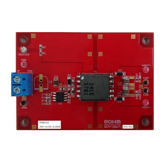
Figure 1. BD7F100EFJ-EVK-002 Evaluation Board
Top View
© 2017 ROHM Co., Ltd.
= -15V, Unless otherwise specified.
OUT2
Min
24.0
15.0
-15.0
3.2
3.2
81.7
Typ
Max
Units
V
V
V
165
mA
165
mA
400
kHz
%
Figure 2. BD7F100EFJ-EVK-002 Evaluation Board
1/5
User's Guide
Conditions
R4=3.9kΩ, R5=76.8kΩ
R4=3.9kΩ, R5=76.8kΩ
Maximum Output Power:5W
I
= 165mA
O
Bottom View
No. 60UG028E Rev.001
OCT.2017
Advertisement
Table of Contents

Subscribe to Our Youtube Channel
Related Manuals for Rohm BD7F100EFJ-EVK-002


Summary of Contents for Rohm BD7F100EFJ-EVK-002
- Page 1 Isolated Flyback DC/DC Converter BD7F100EFJ-LB Evaluation Board BD7F100EFJ-EVK-002 (24V→±15V, 0.165A) BD7F100EFJ-EVK-002 Evaluation board delivers outputs 15volts and -15 volts from an input 24 volts using BD7F100EFJ-LB, Isolated Flyback DC/DC converter integrated circuit, with output current rating of maximum 0.165A. Performance specification These are representative values, and it is not a guaranteed against the characteristics.
- Page 2 (11) Check DC voltmeter 3 displays -15V. (12) The load is enabled. DC Voltmeter 1 DC Voltmeter 2 Load 1 DC Power Load 2 DC Voltmeter 3 Figure 3. Connection Diagram © 2017 ROHM Co., Ltd. No. 60UG028E Rev.001 OCT.2017...
-
Page 3: Circuit Diagram
= 24V, V = 15V, V = -15V OUT1 OUT2 SDX/EN VOUT+ AGND VOUT- SDX/EN COMP PGND Figure 4. BD7F100EFJ-EVK-002 Circuit Diagram Bill of Materials Value Description Size Part Number / Series Manufactuer 1μF Capacitor, Chip, 50V, X7R 2012 GRM21BR71H105KA12 MURATA 4.7μF... - Page 4 (Top View) Figure 7. Top Side Layout Figure 8. Middle Layer1 Layout (Top View) (Top View) Figure 9. Middle Layer2 Layout Figure 10. Bottom Side Layer Layout (Top View) (Top View) © 2017 ROHM Co., Ltd. No. 60UG028E Rev.001 OCT.2017...
- Page 5 0.00 0.05 0.10 0.15 OUT1[A] OUT2 Figure 11. Load Regulation (V Figure 12. Load Regulation (V OUT1 OUT2 0.00 0.05 0.10 0.15 Figure 13. Efficiency vs Load Current =I OUT1 OUT2 © 2017 ROHM Co., Ltd. No. 60UG028E Rev.001 OCT.2017...
- Page 6 Products. ROHM does not grant you, explicitly or implicitly, any license to use or exercise intellectual property or other rights held by ROHM or any other parties. ROHM shall have no responsibility whatsoever for any dispute arising out of the use of such technical information.
Need help?
Do you have a question about the BD7F100EFJ-EVK-002 and is the answer not in the manual?
Questions and answers