Advertisement
Switching Regulator Series
Isolated Flyback DC/DC Converter
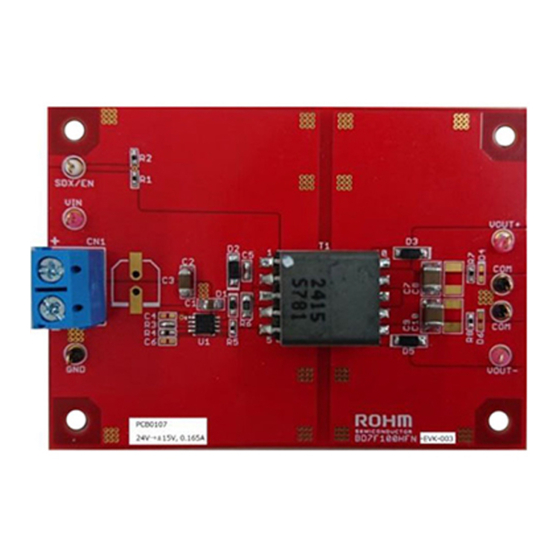
BD7F100HFN-LB Evaluation Board
BD7F100HFN-EVK-002 (24V→5V, 1A)
BD7F100HFN-EVK-002 Evaluation board delivers an output 5 volts from an input 24 volts using BD7F100HFN-LB, Isolated Flyback DC/DC
converter integrated circuit, with output current rating of maximum 1A.
Performance specification
These are representative values, and it is not a guaranteed against the characteristics.
V
= 24V, V
= 5V, Unless otherwise specified.
IN
OUT
Parameter
Input Voltage
Output Voltage
Output Current Range
Operating Frequency
Maximum Efficiency
Evaluation Board
PCB size: 70mm×50mm×1.6mm
Figure 1. BD7F100HFN-EVK-002 Evaluation Board
Top View
© 2017 ROHM Co., Ltd.
Min
Typ
Max
24.0
5.0
13.8
1000
400
77.5
Figure 2. BD7F100HFN-EVK-002 Evaluation Board
1/5
User's Guide
Units
Conditions
V
R4=3.9kΩ, R5=80.6kΩ
V
mA
Maximum Output Power:5W
kHz
%
I
= 1000mA
O
Bottom View
No. 60UG032E Rev.002
NOV.2018
Advertisement
Table of Contents

Related Manuals for Rohm BD7F100HFN-LB


Summary of Contents for Rohm BD7F100HFN-LB
- Page 1 Isolated Flyback DC/DC Converter BD7F100HFN-LB Evaluation Board BD7F100HFN-EVK-002 (24V→5V, 1A) BD7F100HFN-EVK-002 Evaluation board delivers an output 5 volts from an input 24 volts using BD7F100HFN-LB, Isolated Flyback DC/DC converter integrated circuit, with output current rating of maximum 1A. Performance specification These are representative values, and it is not a guaranteed against the characteristics.
-
Page 2: Operation Procedures
(7) DC power-supply output is turned ON. (8) Check DC voltmeter 2 displays 5V. (9) The load is enabled. DC Voltmeter 1 DC Voltmeter 2 Load DC Power Figure 3. Connection Diagram © 2017 ROHM Co., Ltd. No. 60UG032E Rev.002 NOV.2018... -
Page 3: Circuit Diagram
Resistor, Chip, 2/5W, 1% 2012 ESR10EZPF1001 ROHM 330Ω Resistor, Chip, 1/10W, 1% 1608 MCR03EZPFX3300 ROHM 63μH Transformer, Np:Ns=3:1, ±20% 13.5 x 20.0 x 12.5mm CEP1311D-2405051R sumida BD7F100HFN I.C. BD7F100HFN HSON8 BD7F100HFN ROHM © 2017 ROHM Co., Ltd. No. 60UG032E Rev.002 NOV.2018... - Page 4 (Top View) Figure 7. Top Side Layout Figure 8. Middle Layer1 Layout (Top View) (Top View) Figure 9. Middle Layer2 Layout Figure 10. Bottom Side Layer Layout (Top View) (Top View) © 2017 ROHM Co., Ltd. No. 60UG032E Rev.002 NOV.2018...
-
Page 5: Reference Application Data
BD7F100HFN-EVK-002 User’s Guide Reference Application Data = 24V, V = 5V Figure 11. Efficiency vs Load Current Figure 12. Load Regulation © 2017 ROHM Co., Ltd. No. 60UG032E Rev.002 NOV.2018... - Page 6 Products. ROHM does not grant you, explicitly or implicitly, any license to use or exercise intellectual property or other rights held by ROHM or any other parties. ROHM shall have no responsibility whatsoever for any dispute arising out of the use of such technical information.
- Page 7 [8] Be sure to wear insulated gloves when handling is required during operation. After Use [9] The ROHM Evaluation Board contains the circuits which store the high voltage. Since it stores the charges even after the connected power circuits are cut, please discharge the electricity after using it, and please deal with it after confirming such electric discharge.
Need help?
Do you have a question about the BD7F100HFN-LB and is the answer not in the manual?
Questions and answers